EP0124628A1 - Moissonneuse-batteuse à dispositif de battage à écoulement axial - Google Patents
Moissonneuse-batteuse à dispositif de battage à écoulement axial Download PDFInfo
- Publication number
- EP0124628A1 EP0124628A1 EP83104397A EP83104397A EP0124628A1 EP 0124628 A1 EP0124628 A1 EP 0124628A1 EP 83104397 A EP83104397 A EP 83104397A EP 83104397 A EP83104397 A EP 83104397A EP 0124628 A1 EP0124628 A1 EP 0124628A1
- Authority
- EP
- European Patent Office
- Prior art keywords
- drum
- threshing
- chopping
- arrangement
- combine
- Prior art date
- Legal status (The legal status is an assumption and is not a legal conclusion. Google has not performed a legal analysis and makes no representation as to the accuracy of the status listed.)
- Withdrawn
Links
Images


Classifications
-
- A—HUMAN NECESSITIES
- A01—AGRICULTURE; FORESTRY; ANIMAL HUSBANDRY; HUNTING; TRAPPING; FISHING
- A01F—PROCESSING OF HARVESTED PRODUCE; HAY OR STRAW PRESSES; DEVICES FOR STORING AGRICULTURAL OR HORTICULTURAL PRODUCE
- A01F7/00—Threshing apparatus
- A01F7/02—Threshing apparatus with rotating tools
- A01F7/06—Threshing apparatus with rotating tools with axles in line with the feeding direction ; Axial threshing machines
-
- A—HUMAN NECESSITIES
- A01—AGRICULTURE; FORESTRY; ANIMAL HUSBANDRY; HUNTING; TRAPPING; FISHING
- A01F—PROCESSING OF HARVESTED PRODUCE; HAY OR STRAW PRESSES; DEVICES FOR STORING AGRICULTURAL OR HORTICULTURAL PRODUCE
- A01F12/00—Parts or details of threshing apparatus
- A01F12/40—Arrangements of straw crushers or cutters
Definitions
- the present invention relates to a combine harvester with an axial threshing machine with a mowing device, an adjoining conveying device for the cut crop, a rotating threshing and separating drum arranged in a drum housing for axial threshing of the crop, an insertion device for introducing the crop delivered by the conveyor into the drum housing , one of the threshing and separating drum chopping device and a fan wheel for ejecting the threshed crop.
- the crop for example grain
- a cutting device is cut with a cutting device and then fed to the threshing and separating device of the axial threshing machine via a conveyor system.
- This usually has a threshing and separating drum arranged in the longitudinal direction, in which the cut crop is guided in helical lines around a rotor and threshed out with the help of threshing elements.
- the threshed and still chaff and other small impurity-containing grain material falls through a concave to a V orberei- tung ground below the threshing drum, the straw while in the direction towards the rear end of the threshing drum is guided.
- Grain contained in straw also falls through the separating sieves onto the step floor or directly the cleaning bead.
- the still contaminated grain is transported on the preparation floor by shaking in the direction of its end, from where it falls down onto a sieve arrangement.
- An air stream from a cleaning fan blows through the sieve arrangement, through which the impurities still contained in the grain, such as chaff, etc., are captured and blown out.
- the cleaned grain falling through the sieves is collected and transferred to a grain tank using a grain elevator.
- a combine harvester with an axial threshing machine is known from DE-OS 31 48 369, in which; Seen in the direction of travel of the machine, behind the threshing and separating drum a chopper-ejector combination is provided at the outlet, which rotates in the same direction as the threshing drum, wipes off the plant parts discharged from the rotor blades, shreds them and rearwards into one Throws outlet opening to which a spreader can be attached.
- This chopper-ejector combination is driven by a belt drive, which is connected to the belt drive for the rotor.
- a lower chopping speed can be achieved in that the drive belt runs over different types of pulleys, while the chopper can optionally be switched off by a magnetic coupling in the chopper drive countershaft.
- the chopper-ejector combination of this well-known combine is at the rear end next to the separating drum, i.e. axially parallel to the drum shaft.
- the object of the present invention is to improve and design a combine harvester with an axial threshing machine of the type mentioned at the outset in such a way that it has a particularly compact design that the threshed, delivered by the combine has a desired length for the intended use and that the speed of the chopping arrangement and the impeller are individually adjustable for different crops.
- the drives for the chopping arrangement and the impeller as well as the threshing drum are belt drives, each of which is fed to them arranged to run pulley connected to the shaft of a drive motor.
- the drive belts are preferably assigned tensioning rollers, by pressing them on the drive belts, the chopping arrangement with the blower or the drum are actuated.
- a detachable plug connection is provided between the chopping arrangement and the threshing drum, by snapping the chopping arrangement together with the impeller with the threshing drum.
- the chopping arrangement itself has knives and counter knives which can be pivoted both into a working position and into a rest position.
- the chopping arrangement has a disk which is rotatably mounted on the drum shaft, the disk being equipped with a plurality of pairs of chopping knives, each pair being fastened to an axis which passes through an elongated hole in the disk, and next to the Elongated holes bolts are provided which limit the lateral pivoting movement of the chopper knives and a locking arrangement is provided on the disc for locking or unlocking the chopping arrangement in its rest or Working position.
- the inventive coupling of the two drives, one for the threshing drum and the other for the chopping arrangement and the impeller, enables the chopping arrangement to be easily switched on and off. Furthermore, the machine according to the invention enables the rotational speed to be varied on different crops, and the threshed crop to be varied on un-chopped, partially chopped and fully chopped, with the additional advantage of a compact design being achieved.
- FIG. 1 shows a self-propelled combine harvester with an axial threshing machine 1 for harvesting and threshing, for example, grain.
- the combine has an indicated cutting tool 2 and a conveyor 3, with which the cut crop is in this case introduced into the axial threshing machine 5 via a feed roller 4.
- the axial threshing machine has a threshing drum 6 in the form of a rotor, which is enclosed by a cylindrical jacket housing 9, the lower part of the jacket housing 9 being formed by a Dresden basket arrangement 11 or separating basket arrangement 11 '.
- threshing strips 7 are provided in the area of the concave in helical lines, which cooperate with guide plates fixed in the upper area and within the casing 9 and also arranged in a helical manner.
- a motor 41 FIG. 2
- the crop is threshed out in this area.
- the grains fall down through the holes of the concave or the concave arrangement 11 onto a step bottom 10, or through the holes of the separating basket 11 'onto a sieve device 14, 15, the grains also through the sieve chaff or other small impurities are added to the concave and the separating basket 11 '.
- the flat step floor 10 also has a plurality of slope strips running in the longitudinal direction of the threshing machine, by means of which the surface of the step floor is subdivided several times overall. This slope ledge prevents the grain from slipping excessively sideways on the sieve bottom in the event of extreme side slopes of the combine.
- a blower 19 is provided below the step floor along which the threshed grain with the impurities is transported backwards onto the sieve arrangement 14, 15 by means of shaking movements, the air flow of which flows through the grain material deposited on the sieves of the sieve arrangement and thus the chaff and other impurities contained therein away.
- the grain material cleaned in this way and falling downward from the sieve arrangement into a collecting chamber 16 is conveyed by a grain conveyor 17 into a grain tank 18.
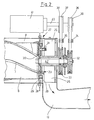
- the combine harvester is provided with front relatively large drive wheels 25 and with two smaller rear steering wheels 21 which support the chassis 24. Between the threshing drum 6 and the drum wall 9 is a annular gap 8 is formed through which the now threshed crop is fed to the rear part of the combine harvester, which is partially enlarged and shown in plan view in FIG. 2.
- a chopping arrangement 27 and an impeller 26 are rotatably arranged on the shaft 42 for the threshing and separating drum 6 and thus coaxially with it.
- the drive for the shaft 42 of the separating drum is effected by a motor, designated 41, on the shaft 40 of which a pulley 39 is arranged.
- a drive belt 36 runs over this belt pulley 39 and drives a belt pulley 32 which is fixedly connected to the shaft 42.
- a pulley 38 is also provided on the shaft 40 of the motor 41, via which a drive belt 37 runs, which drives a pulley 33 which is connected to the chopping arrangement 27 and the impeller 26.
- two idlers 34, 35 are provided. By pressing these tension rollers onto the associated drive belts, they are brought into drive connection with the corresponding belt wheels. By loosening the tension roller 35, the belt 37 can be relaxed so that the chopping arrangement 27 and the impeller 26 no longer necessarily rotate.
- a plug connection 31 is provided, through which the disk 30 or the impeller 26 are coupled to the drum 6 can. By simply pivoting a handle connected to this plug connection 31, it engages in corresponding recesses at the rear end of the drum 6.
- Figures 3 and 4 show a section along the line AA of Figure 1 and offer a plan view of the chopping arrangement.
- this has a locking device 23 with which it can be locked.
- pairs of chopping knives 29 are arranged along their circumference, each of which is connected to one another by an axis passing through the disk 30.
- the Axis passes through an elongated hole 44 so that it can be moved slightly.
- Stop bolts 43, 43 ' are also provided on the disk 30, which limit the lateral deflection of the swiveling chopper knives 29.
- these knives can be pivoted into a rest position, as a result of which the crop to be ejected to the rear is not chopped, as is necessary, for example, if the straw subsequently closes Bale to be pressed.
- the counter knives 28 are then pivoted so that they assume a rest position in which the crop material emerging from the annular gap leaves the combine harvester through the exit opening 13 without being chopped.
- the lock 23 is pivoted manually from the position II in FIG. 3 to the position I in FIG. 4, the setting shown in FIG. 3 being achieved by taking the chopping knives 29 with the stop bolts 43 ′. Then the counter knife 28 are swung out.
- Another possibility is to achieve a partial chopping of the crop by moving the chopping knives 29 into their cutting position shown in FIG. 4 are pivoted, but the counter knife 28 assume their rest position shown in Figure 3; this results in a free cut without counter knife, whereby a coarser chopped material is achieved.
- the drives for both the separating drum and the chopping arrangement can thus be adjusted separately. Any switching on and off of the chopping device with different chopping effect can be easily achieved. Due to the concentric design on the drum shaft, an overall compact, short design of the axial threshing machine is achieved. A variation in the length of the crop that occurs can be achieved from un-chopped to partially chopped to fully chopped.
Priority Applications (1)
| Application Number | Priority Date | Filing Date | Title |
|---|---|---|---|
| EP83104397A EP0124628A1 (fr) | 1983-05-04 | 1983-05-04 | Moissonneuse-batteuse à dispositif de battage à écoulement axial |
Applications Claiming Priority (1)
| Application Number | Priority Date | Filing Date | Title |
|---|---|---|---|
| EP83104397A EP0124628A1 (fr) | 1983-05-04 | 1983-05-04 | Moissonneuse-batteuse à dispositif de battage à écoulement axial |
Publications (1)
| Publication Number | Publication Date |
|---|---|
| EP0124628A1 true EP0124628A1 (fr) | 1984-11-14 |
Family
ID=8190448
Family Applications (1)
| Application Number | Title | Priority Date | Filing Date |
|---|---|---|---|
| EP83104397A Withdrawn EP0124628A1 (fr) | 1983-05-04 | 1983-05-04 | Moissonneuse-batteuse à dispositif de battage à écoulement axial |
Country Status (1)
| Country | Link |
|---|---|
| EP (1) | EP0124628A1 (fr) |
Cited By (10)
| Publication number | Priority date | Publication date | Assignee | Title |
|---|---|---|---|---|
| BE1006791A3 (fr) * | 1989-06-01 | 1994-12-13 | Claas Ohg | Moissonneuse-batteuse automotrice comportant un mecanisme de battage et de separation dans le sens axial. |
| EP0631717A1 (fr) * | 1993-07-01 | 1995-01-04 | CLAAS Kommanditgesellschaft auf Aktien | Accessoire hacheur pour moissonneuse-batteuse à repartir le mélange de balles et de menues pailles |
| EP0748583A1 (fr) * | 1995-06-17 | 1996-12-18 | CLAAS KGaA | Moissonneuse-batteuse |
| EP0832553A2 (fr) * | 1996-09-30 | 1998-04-01 | CLAAS KGaA | Moissonneuse-batteuse |
| EP0832554A2 (fr) * | 1996-09-30 | 1998-04-01 | CLAAS KGaA | Moissonneuse-batteuse |
| DE19722793A1 (de) * | 1997-05-30 | 1998-12-03 | Claas Selbstfahr Erntemasch | Mähdrescher |
| EP1031270A1 (fr) * | 1999-02-24 | 2000-08-30 | Deere & Company | Dispositif séparateur à écoulement axial pour moissonneuse-batteuse |
| CN107046951A (zh) * | 2017-02-17 | 2017-08-18 | 中国农业科学院棉花研究所 | 一种种子脱粒设备 |
| WO2021207296A1 (fr) * | 2020-04-09 | 2021-10-14 | Cnh Industrial America Llc | Système de battage et hachoir pour moissonneuse-batteuse |
| CN114514828A (zh) * | 2022-04-07 | 2022-05-20 | 农业农村部南京农业机械化研究所 | 一种脱粒清选装置及联合收获机 |
Citations (2)
| Publication number | Priority date | Publication date | Assignee | Title |
|---|---|---|---|---|
| DE1264132B (de) * | 1965-11-30 | 1968-03-21 | Massey Ferguson G M B H | In einem Maehdrescher verwendbare Trenneinrichtung |
| DE2835899A1 (de) * | 1977-08-18 | 1979-03-01 | Deere & Co | Maehdrescher |
-
1983
- 1983-05-04 EP EP83104397A patent/EP0124628A1/fr not_active Withdrawn
Patent Citations (2)
| Publication number | Priority date | Publication date | Assignee | Title |
|---|---|---|---|---|
| DE1264132B (de) * | 1965-11-30 | 1968-03-21 | Massey Ferguson G M B H | In einem Maehdrescher verwendbare Trenneinrichtung |
| DE2835899A1 (de) * | 1977-08-18 | 1979-03-01 | Deere & Co | Maehdrescher |
Cited By (19)
| Publication number | Priority date | Publication date | Assignee | Title |
|---|---|---|---|---|
| BE1006791A3 (fr) * | 1989-06-01 | 1994-12-13 | Claas Ohg | Moissonneuse-batteuse automotrice comportant un mecanisme de battage et de separation dans le sens axial. |
| EP0631717A1 (fr) * | 1993-07-01 | 1995-01-04 | CLAAS Kommanditgesellschaft auf Aktien | Accessoire hacheur pour moissonneuse-batteuse à repartir le mélange de balles et de menues pailles |
| US5769711A (en) * | 1995-06-17 | 1998-06-23 | Claas Kgaa | Harvester thresher |
| EP0748583A1 (fr) * | 1995-06-17 | 1996-12-18 | CLAAS KGaA | Moissonneuse-batteuse |
| EP0832554A3 (fr) * | 1996-09-30 | 1998-07-08 | CLAAS KGaA | Moissonneuse-batteuse |
| US5913724A (en) * | 1996-09-30 | 1999-06-22 | Claas Kgaa | Combine harvester |
| DE19640047A1 (de) * | 1996-09-30 | 1998-04-02 | Claas Ohg | Mähdrescher |
| EP0832554A2 (fr) * | 1996-09-30 | 1998-04-01 | CLAAS KGaA | Moissonneuse-batteuse |
| EP0832553A2 (fr) * | 1996-09-30 | 1998-04-01 | CLAAS KGaA | Moissonneuse-batteuse |
| US5928079A (en) * | 1996-09-30 | 1999-07-27 | Claas Kgaa | Combine harvester |
| EP0832553A3 (fr) * | 1996-09-30 | 1999-03-31 | CLAAS KGaA | Moissonneuse-batteuse |
| DE19640055A1 (de) * | 1996-09-30 | 1998-04-02 | Claas Ohg | Mähdrescher |
| DE19722793A1 (de) * | 1997-05-30 | 1998-12-03 | Claas Selbstfahr Erntemasch | Mähdrescher |
| US6152820A (en) * | 1997-05-30 | 2000-11-28 | Claas Selbstfahrende Erntemaschinen Gmbh | Chopping device in a combine |
| EP1031270A1 (fr) * | 1999-02-24 | 2000-08-30 | Deere & Company | Dispositif séparateur à écoulement axial pour moissonneuse-batteuse |
| CN107046951A (zh) * | 2017-02-17 | 2017-08-18 | 中国农业科学院棉花研究所 | 一种种子脱粒设备 |
| CN107046951B (zh) * | 2017-02-17 | 2023-09-19 | 中国农业科学院棉花研究所 | 一种种子脱粒设备 |
| WO2021207296A1 (fr) * | 2020-04-09 | 2021-10-14 | Cnh Industrial America Llc | Système de battage et hachoir pour moissonneuse-batteuse |
| CN114514828A (zh) * | 2022-04-07 | 2022-05-20 | 农业农村部南京农业机械化研究所 | 一种脱粒清选装置及联合收获机 |
Similar Documents
| Publication | Publication Date | Title |
|---|---|---|
| DE2628706C2 (fr) | ||
| DE2729033C2 (fr) | ||
| DE2132211C2 (de) | Mähdrescher der Axialflußbauart | |
| DE2245602C2 (de) | Zwischen Mäh- und Dreschwerk eines Mähdreschers angeordnete Zuführungseinrichtung für Erntegut | |
| DE2729012C2 (de) | Mähdrescher der Axialflußbauart | |
| EP0092805B1 (fr) | Moissonneuse-batteuse | |
| EP0058431B1 (fr) | Machine à récolter les fourrages | |
| EP0522267B1 (fr) | Séparateur axial | |
| DE2430718B2 (de) | Mähdrescher | |
| EP0521280B1 (fr) | Séparateur axial | |
| EP0166116A2 (fr) | Moissonneuse-batteuse | |
| EP1228683B1 (fr) | Moissoneuse batteuse avec un transporteur rotatif | |
| DE2616535A1 (de) | Maehdrescher mit nachdreschvorrichtung | |
| DE3122920C2 (fr) | ||
| DE3025380C2 (fr) | ||
| DE19650058A1 (de) | Häckseltrommel | |
| DE2317048A1 (de) | Maehdrescher | |
| EP0124628A1 (fr) | Moissonneuse-batteuse à dispositif de battage à écoulement axial | |
| DE1297390B (de) | Dresch- und Trennvorrichtung fuer im Querlaengsfluss arbeitende Maehdrescher | |
| EP0503444A1 (fr) | Batte pour batteur cylindrique | |
| DE2220825C2 (de) | Feldhäcksler | |
| DE3406201C3 (fr) | ||
| EP0095713B1 (fr) | Moissonneuse-batteuse avec un dispositif de ramassage | |
| EP0862850B1 (fr) | Moissonneuse-batteuse | |
| DE2503693A1 (de) | Kornabscheidevorrichtung fuer einen maehdrescher |
Legal Events
| Date | Code | Title | Description |
|---|---|---|---|
| PUAI | Public reference made under article 153(3) epc to a published international application that has entered the european phase |
Free format text: ORIGINAL CODE: 0009012 |
|
| 17P | Request for examination filed |
Effective date: 19840221 |
|
| AK | Designated contracting states |
Designated state(s): BE DE FR GB IT |
|
| STAA | Information on the status of an ep patent application or granted ep patent |
Free format text: STATUS: THE APPLICATION HAS BEEN WITHDRAWN |
|
| 18W | Application withdrawn |
Withdrawal date: 19860228 |
|
| RIN1 | Information on inventor provided before grant (corrected) |
Inventor name: AHLE, JOSEF |