EP0124628A1 - Combine with an axial flow threshing device - Google Patents
Combine with an axial flow threshing device Download PDFInfo
- Publication number
- EP0124628A1 EP0124628A1 EP83104397A EP83104397A EP0124628A1 EP 0124628 A1 EP0124628 A1 EP 0124628A1 EP 83104397 A EP83104397 A EP 83104397A EP 83104397 A EP83104397 A EP 83104397A EP 0124628 A1 EP0124628 A1 EP 0124628A1
- Authority
- EP
- European Patent Office
- Prior art keywords
- drum
- threshing
- chopping
- arrangement
- combine
- Prior art date
- Legal status (The legal status is an assumption and is not a legal conclusion. Google has not performed a legal analysis and makes no representation as to the accuracy of the status listed.)
- Withdrawn
Links
Images


Classifications
-
- A—HUMAN NECESSITIES
- A01—AGRICULTURE; FORESTRY; ANIMAL HUSBANDRY; HUNTING; TRAPPING; FISHING
- A01F—PROCESSING OF HARVESTED PRODUCE; HAY OR STRAW PRESSES; DEVICES FOR STORING AGRICULTURAL OR HORTICULTURAL PRODUCE
- A01F7/00—Threshing apparatus
- A01F7/02—Threshing apparatus with rotating tools
- A01F7/06—Threshing apparatus with rotating tools with axles in line with the feeding direction ; Axial threshing machines
-
- A—HUMAN NECESSITIES
- A01—AGRICULTURE; FORESTRY; ANIMAL HUSBANDRY; HUNTING; TRAPPING; FISHING
- A01F—PROCESSING OF HARVESTED PRODUCE; HAY OR STRAW PRESSES; DEVICES FOR STORING AGRICULTURAL OR HORTICULTURAL PRODUCE
- A01F12/00—Parts or details of threshing apparatus
- A01F12/40—Arrangements of straw crushers or cutters
Definitions
- the present invention relates to a combine harvester with an axial threshing machine with a mowing device, an adjoining conveying device for the cut crop, a rotating threshing and separating drum arranged in a drum housing for axial threshing of the crop, an insertion device for introducing the crop delivered by the conveyor into the drum housing , one of the threshing and separating drum chopping device and a fan wheel for ejecting the threshed crop.
- the crop for example grain
- a cutting device is cut with a cutting device and then fed to the threshing and separating device of the axial threshing machine via a conveyor system.
- This usually has a threshing and separating drum arranged in the longitudinal direction, in which the cut crop is guided in helical lines around a rotor and threshed out with the help of threshing elements.
- the threshed and still chaff and other small impurity-containing grain material falls through a concave to a V orberei- tung ground below the threshing drum, the straw while in the direction towards the rear end of the threshing drum is guided.
- Grain contained in straw also falls through the separating sieves onto the step floor or directly the cleaning bead.
- the still contaminated grain is transported on the preparation floor by shaking in the direction of its end, from where it falls down onto a sieve arrangement.
- An air stream from a cleaning fan blows through the sieve arrangement, through which the impurities still contained in the grain, such as chaff, etc., are captured and blown out.
- the cleaned grain falling through the sieves is collected and transferred to a grain tank using a grain elevator.
- a combine harvester with an axial threshing machine is known from DE-OS 31 48 369, in which; Seen in the direction of travel of the machine, behind the threshing and separating drum a chopper-ejector combination is provided at the outlet, which rotates in the same direction as the threshing drum, wipes off the plant parts discharged from the rotor blades, shreds them and rearwards into one Throws outlet opening to which a spreader can be attached.
- This chopper-ejector combination is driven by a belt drive, which is connected to the belt drive for the rotor.
- a lower chopping speed can be achieved in that the drive belt runs over different types of pulleys, while the chopper can optionally be switched off by a magnetic coupling in the chopper drive countershaft.
- the chopper-ejector combination of this well-known combine is at the rear end next to the separating drum, i.e. axially parallel to the drum shaft.
- the object of the present invention is to improve and design a combine harvester with an axial threshing machine of the type mentioned at the outset in such a way that it has a particularly compact design that the threshed, delivered by the combine has a desired length for the intended use and that the speed of the chopping arrangement and the impeller are individually adjustable for different crops.
- the drives for the chopping arrangement and the impeller as well as the threshing drum are belt drives, each of which is fed to them arranged to run pulley connected to the shaft of a drive motor.
- the drive belts are preferably assigned tensioning rollers, by pressing them on the drive belts, the chopping arrangement with the blower or the drum are actuated.
- a detachable plug connection is provided between the chopping arrangement and the threshing drum, by snapping the chopping arrangement together with the impeller with the threshing drum.
- the chopping arrangement itself has knives and counter knives which can be pivoted both into a working position and into a rest position.
- the chopping arrangement has a disk which is rotatably mounted on the drum shaft, the disk being equipped with a plurality of pairs of chopping knives, each pair being fastened to an axis which passes through an elongated hole in the disk, and next to the Elongated holes bolts are provided which limit the lateral pivoting movement of the chopper knives and a locking arrangement is provided on the disc for locking or unlocking the chopping arrangement in its rest or Working position.
- the inventive coupling of the two drives, one for the threshing drum and the other for the chopping arrangement and the impeller, enables the chopping arrangement to be easily switched on and off. Furthermore, the machine according to the invention enables the rotational speed to be varied on different crops, and the threshed crop to be varied on un-chopped, partially chopped and fully chopped, with the additional advantage of a compact design being achieved.
- FIG. 1 shows a self-propelled combine harvester with an axial threshing machine 1 for harvesting and threshing, for example, grain.
- the combine has an indicated cutting tool 2 and a conveyor 3, with which the cut crop is in this case introduced into the axial threshing machine 5 via a feed roller 4.
- the axial threshing machine has a threshing drum 6 in the form of a rotor, which is enclosed by a cylindrical jacket housing 9, the lower part of the jacket housing 9 being formed by a Dresden basket arrangement 11 or separating basket arrangement 11 '.
- threshing strips 7 are provided in the area of the concave in helical lines, which cooperate with guide plates fixed in the upper area and within the casing 9 and also arranged in a helical manner.
- a motor 41 FIG. 2
- the crop is threshed out in this area.
- the grains fall down through the holes of the concave or the concave arrangement 11 onto a step bottom 10, or through the holes of the separating basket 11 'onto a sieve device 14, 15, the grains also through the sieve chaff or other small impurities are added to the concave and the separating basket 11 '.
- the flat step floor 10 also has a plurality of slope strips running in the longitudinal direction of the threshing machine, by means of which the surface of the step floor is subdivided several times overall. This slope ledge prevents the grain from slipping excessively sideways on the sieve bottom in the event of extreme side slopes of the combine.
- a blower 19 is provided below the step floor along which the threshed grain with the impurities is transported backwards onto the sieve arrangement 14, 15 by means of shaking movements, the air flow of which flows through the grain material deposited on the sieves of the sieve arrangement and thus the chaff and other impurities contained therein away.
- the grain material cleaned in this way and falling downward from the sieve arrangement into a collecting chamber 16 is conveyed by a grain conveyor 17 into a grain tank 18.
- the combine harvester is provided with front relatively large drive wheels 25 and with two smaller rear steering wheels 21 which support the chassis 24. Between the threshing drum 6 and the drum wall 9 is a annular gap 8 is formed through which the now threshed crop is fed to the rear part of the combine harvester, which is partially enlarged and shown in plan view in FIG. 2.
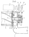
- a chopping arrangement 27 and an impeller 26 are rotatably arranged on the shaft 42 for the threshing and separating drum 6 and thus coaxially with it.
- the drive for the shaft 42 of the separating drum is effected by a motor, designated 41, on the shaft 40 of which a pulley 39 is arranged.
- a drive belt 36 runs over this belt pulley 39 and drives a belt pulley 32 which is fixedly connected to the shaft 42.
- a pulley 38 is also provided on the shaft 40 of the motor 41, via which a drive belt 37 runs, which drives a pulley 33 which is connected to the chopping arrangement 27 and the impeller 26.
- two idlers 34, 35 are provided. By pressing these tension rollers onto the associated drive belts, they are brought into drive connection with the corresponding belt wheels. By loosening the tension roller 35, the belt 37 can be relaxed so that the chopping arrangement 27 and the impeller 26 no longer necessarily rotate.
- a plug connection 31 is provided, through which the disk 30 or the impeller 26 are coupled to the drum 6 can. By simply pivoting a handle connected to this plug connection 31, it engages in corresponding recesses at the rear end of the drum 6.
- Figures 3 and 4 show a section along the line AA of Figure 1 and offer a plan view of the chopping arrangement.
- this has a locking device 23 with which it can be locked.
- pairs of chopping knives 29 are arranged along their circumference, each of which is connected to one another by an axis passing through the disk 30.
- the Axis passes through an elongated hole 44 so that it can be moved slightly.
- Stop bolts 43, 43 ' are also provided on the disk 30, which limit the lateral deflection of the swiveling chopper knives 29.
- these knives can be pivoted into a rest position, as a result of which the crop to be ejected to the rear is not chopped, as is necessary, for example, if the straw subsequently closes Bale to be pressed.
- the counter knives 28 are then pivoted so that they assume a rest position in which the crop material emerging from the annular gap leaves the combine harvester through the exit opening 13 without being chopped.
- the lock 23 is pivoted manually from the position II in FIG. 3 to the position I in FIG. 4, the setting shown in FIG. 3 being achieved by taking the chopping knives 29 with the stop bolts 43 ′. Then the counter knife 28 are swung out.
- Another possibility is to achieve a partial chopping of the crop by moving the chopping knives 29 into their cutting position shown in FIG. 4 are pivoted, but the counter knife 28 assume their rest position shown in Figure 3; this results in a free cut without counter knife, whereby a coarser chopped material is achieved.
- the drives for both the separating drum and the chopping arrangement can thus be adjusted separately. Any switching on and off of the chopping device with different chopping effect can be easily achieved. Due to the concentric design on the drum shaft, an overall compact, short design of the axial threshing machine is achieved. A variation in the length of the crop that occurs can be achieved from un-chopped to partially chopped to fully chopped.
Landscapes
- Life Sciences & Earth Sciences (AREA)
- Environmental Sciences (AREA)
- Threshing Machine Elements (AREA)
Abstract
Description
Die vorliegende Erfindung betrifft einen Mähdrescher mit Axialdreschmaschine mit einer Mähvorrichtung, einer sich daran anschließenden Fördereinrichtung für das geschnittene Erntegut , einer in einem Trommelgehäuse angeordneten , rotierenden Dresch- und Trenntrommel zum Axialdrusch des Erntegutes, einer Einbringvorrichtung zum Einbringen des vom Förderer angelieferten Erntegutes in das Trommelgehäuse, einer der Dresch- und Trenntrommel nachgeordneten Häckseleinrichtung sowie einem Gebläserad zum Auswerfen des ausgedroschenen Erntegutes.The present invention relates to a combine harvester with an axial threshing machine with a mowing device, an adjoining conveying device for the cut crop, a rotating threshing and separating drum arranged in a drum housing for axial threshing of the crop, an insertion device for introducing the crop delivered by the conveyor into the drum housing , one of the threshing and separating drum chopping device and a fan wheel for ejecting the threshed crop.
Bei derartigen Mähdeschern wird das Erntegut,z.B. Getreide, mit einem Schneidwerk geschnitten und anschließend über ein Fördersystem der Dresch- und Trenneinrichtung der Axialdreschmaschine zugeführt. Diese weist üblicherweise eine in Längsrichtung angeordnete Dresch- und Trenntrommel auf, in der das geschnittene Erntegut in Schraubenlinien um einen Rotor geführt und mit Hilfe von Dreschorganen ausgedroschen wird. Das ausgedroschene und noch Spreu sowie andere kleine Verunreinigungen enthaltende Korngut fällt durch einen Dreschkorb auf einen Vorberei- tungsboden unterhalb der Dreschtrommel , wohingegen das Stroh in Richtung auf das hintere Ende der Dreschtrommel geführt wird. Im Stroh enthaltenes Korngut fällt durch Trennsiebe ebenfalls auf den Stufenboden oder direkt auf die Reinigungssicke. Auf dem Vorbereitungsboden wird das noch verunreinigte Korngut durch Rüttelbewegungen in Richtung auf dessen Ende transportiert, von wo es nach unten auf eine Siebanordnung fällt. Die Siebanordnung wird von einem Luftstrom eines Reinigungsgebläses durchblasen, durch den die noch in dem Korngut enthaltenen Verunreinigungen , wie Spreu etc., erfaßt und ausgeblasen werden. Das dabei die Siebe durchfallende gereinigte Korngut wird gesammelt und mit einem Körnerelevator in einen Korntank überführt.With such combine harvesters, the crop, for example grain, is cut with a cutting device and then fed to the threshing and separating device of the axial threshing machine via a conveyor system. This usually has a threshing and separating drum arranged in the longitudinal direction, in which the cut crop is guided in helical lines around a rotor and threshed out with the help of threshing elements. The threshed and still chaff and other small impurity-containing grain material falls through a concave to a V orberei- tung ground below the threshing drum, the straw while in the direction towards the rear end of the threshing drum is guided. Grain contained in straw also falls through the separating sieves onto the step floor or directly the cleaning bead. The still contaminated grain is transported on the preparation floor by shaking in the direction of its end, from where it falls down onto a sieve arrangement. An air stream from a cleaning fan blows through the sieve arrangement, through which the impurities still contained in the grain, such as chaff, etc., are captured and blown out. The cleaned grain falling through the sieves is collected and transferred to a grain tank using a grain elevator.
Aus der DE-OS 28 35 899 ist ein Mähdrescher mit Axialdreschmaschine bekannt. Bei diesem bekannten Mähdrescher wird der Hauptanteil des ausgedroschenen Erntegutes durch den konischen Zwischenraum zwischen der Dreschtrommel und der Trenntrommel zum rückwärtigen Teil der Maschine geleitet, wo es in ein Austraggehäuse gelangt und von Häckselelementen erfaßt wird. Ein Teil des ausgedroschenen Erntegutes wird direkt in ein Gebläsegehäuse geleitet und von dem im Gehäuse angeordneten Gebläserad erfaßt, dessen Drehzahl höher als die Drehzahl der Dreschtrommel ist um dergestalt das ausgedroschene Erntegut zu beschleunigen, bis es etwa die gleiche Umfangsgeschwindigkeit wie die Dreschtrommel aufweist, so daß es beim Verlassen des Gebläsegehäuses eine tangentiale Geschwindigkeit aufweist, die in etwa der Geschwindigkeitskomponente des inneren Teils der Gebläseradschaufeln entspricht.From DE-OS 28 35 899 a combine with an axial threshing machine is known. In this known combine harvester, the main part of the threshed crop is passed through the conical space between the threshing drum and the separating drum to the rear part of the machine, where it gets into a discharge housing and is caught by chopping elements. Part of the threshed crop is fed directly into a blower housing and detected by the fan wheel arranged in the housing, the speed of which is higher than the speed of the threshing drum in order to accelerate the threshed crop until it has approximately the same peripheral speed as the threshing drum, so that there is a tangential speed when leaving the fan housing speed, which corresponds approximately to the speed component of the inner part of the impeller blades.
Weiterhin ist aus der DE-OS 31 48 369 ein Mähdrescher mit Axialdreschmaschine bekannt, bei dem; in Fahrtrichtung der Maschine gesehen, hinter der Dresch- und Trenntrommel eine Häcksler-Auswerfer-Kombination am Auslaß vorgesehen ist, die sich in gleicher Richtung wie die Dreschtrommel dreht, die abgegebenen Pflanzenteile von den Rotor-Flügelschaufeln abstreift, sie zerhäckselt und nach hinten zu einer Auslaßöffnung wirft, an der eine Streueinrichtung angebracht sein kann. Diese Häcksler-Auswerfer-Kombination wird über ein Riemenvorgelege angetrieben, das mit dem Riemenantrieb für den Rotor in Verbindung steht. Eine niedrigere Häckselgeschwindigkeit kann dadurch erreicht werden, daß der Antriebsriemen über verschiedenartige Riemenscheiben verläuft, während durch eine Magnetkupplung im Häckslerantrieb-Vorgelege der Häcksler wahlweise abgeschaltet werden kann. Die Häcksler-Auswerfer-Kombination dieses bekannten Mähdreschers ist am hinteren Ende neben der Trenntrommel , d.h. achsparallel zur Trommelwelle, angeordnet.Furthermore, a combine harvester with an axial threshing machine is known from DE-OS 31 48 369, in which; Seen in the direction of travel of the machine, behind the threshing and separating drum a chopper-ejector combination is provided at the outlet, which rotates in the same direction as the threshing drum, wipes off the plant parts discharged from the rotor blades, shreds them and rearwards into one Throws outlet opening to which a spreader can be attached. This chopper-ejector combination is driven by a belt drive, which is connected to the belt drive for the rotor. A lower chopping speed can be achieved in that the drive belt runs over different types of pulleys, while the chopper can optionally be switched off by a magnetic coupling in the chopper drive countershaft. The chopper-ejector combination of this well-known combine is at the rear end next to the separating drum, i.e. axially parallel to the drum shaft.
Aufgabe der vorliegenden Erfindung ist es, einen Mähdrescher mit Axialdreschmaschine der eingangs näher genannten Art derart zu verbessern und auszugestalten, daß er eine besonders kompakte Bauweise aufweist, daß das ausgedroschene, vom Mähdrescher abgegebene Gut eine für, denjenigen Verwendungszweck gewünschte Länge aufweist und daß die Drehzahl der Häckselanordnung und des Gebläserades für verschiedene Erntegüter individuell einstellbar sind.The object of the present invention is to improve and design a combine harvester with an axial threshing machine of the type mentioned at the outset in such a way that it has a particularly compact design that the threshed, delivered by the combine has a desired length for the intended use and that the speed of the chopping arrangement and the impeller are individually adjustable for different crops.
Ausgehend von einem Mähdrescher der eingangs näher genannten Art, wird zur Lösung dieser Aufgabe vorgeschlagen, daß die Häckselanordnung und das Gebläserad koaxial zur und drehbar auf der Trommelwelle angeordnet sind und daß die Häckselanordnung und das Gebläserad mit einem eigenen Antrieb versehen sind.Starting from a combine harvester of the type mentioned in the introduction, it is proposed to solve this problem that the chopping arrangement and the impeller are arranged coaxially and rotatably on the drum shaft and that the chopping arrangement and the impeller are provided with their own drive.
Mit dieser Anordnung wird der Vorteil erzielt, daß die Häckselanordnung und das Gebläserad unterschiedliche Drehzahlen bezüglich der Dreschtrommel aufweisen.With this arrangement, the advantage is achieved that the chopping arrangement and the impeller have different speeds with respect to the threshing drum.
Damit lassen sich die Drehzahlen sowohl der Häckselanordnung als auch des Gebläserades beliebig auf die verschiedenarrigen Erntegüter und die gewünschte Zerkleinerung einstellen, wobei gleichzeitig eine besonders kurze Bauweise des Mähdreschers erzielt wird.This allows the speeds of both the chopping arrangement and the impeller to be set as required to suit the different crops and the desired size reduction, while at the same time achieving a particularly short design of the combine harvester.
Vorteilhafterweise sind die Antriebe sowohl für die Häckselanordnung und das Gebläserad als auch die Dreschtrommel Riemenantriebe, die jeweils über eine ihnen zugeordnete, mit der Welle eines Antriebsmotors verbundenen Riemenscheibe laufen. Den Antriebsriemen sind vorzugsweise Spannrollen zugeordnet, durch deren Andruck an die Antriebsriemen , die Häckselanordnung mit dem Gebläse bzw. die Trommel betätigt werden. Auf einfache Art und Weise wird dadurch der Vorteil erzielt, daß-die Häckselanordnung mit dem Gebläserad zuschaltbar bzw. abschaltbar sind. Bei abgeschalteter Häckselanordnung bleibt das Erntegut,z.B. Getreidestroh,ungehäckselt, wie es z.B. für den nachfolgenden Verarbeitungsschritt durch eine Großballenpresse wünschenswert ist.Advantageously, the drives for the chopping arrangement and the impeller as well as the threshing drum are belt drives, each of which is fed to them arranged to run pulley connected to the shaft of a drive motor. The drive belts are preferably assigned tensioning rollers, by pressing them on the drive belts, the chopping arrangement with the blower or the drum are actuated. The advantage achieved in a simple manner is that the chopping arrangement can be switched on or off with the impeller. When the chopper arrangement is switched off, the crop, for example grain straw, remains un-chopped, as is desirable, for example, for the subsequent processing step using a large baler.
Bei einem weiteren bevorzugten Ausführungsbeispiel ist eine lösbare Steckerverbindung zwischen Häckselanordnung und Dreschtrommel vorgesehen, durch deren Einrasten die Häckselanordnung zusammen mit dem Gebläserad mit der Dreschtrommel verbindbar sind.In a further preferred exemplary embodiment, a detachable plug connection is provided between the chopping arrangement and the threshing drum, by snapping the chopping arrangement together with the impeller with the threshing drum.
Durch dieses wahlweise Zuschalten und Ausschalten sowohl der Häckseleinrichtung als auch des Gebläserades auf die Geschwindigkeit der Dreschtrommel kann nach dem Lösen der Antriebsverbindung durch die Spannrollen ein Gleichlauf zwischen Häckselanordnung bzw. Gebläserad und Trenntrommel erfolgen, wie es für spezielle Anwendungsgebiete wünschenswert ist.Through this optional switching on and off of both the chopping device and the impeller at the speed of the threshing drum, after loosening the drive connection by the tensioning rollers, synchronism between the chopping arrangement or the impeller and separating drum can take place, as is desirable for special fields of application.
Die Häckselanordnung selbst weist Messer und Gegenmesser auf, die sowohl in eine Arbeitsstellung als auch in eine Ruhestellung verschwenkbar sind.The chopping arrangement itself has knives and counter knives which can be pivoted both into a working position and into a rest position.
Durch Verschwenken der Messer und der Gegenmesser in ihre Ruhestellung wird der Vorteil erzielt, daß das nach hinten auszuwerfende ausgedroschene Erntegut nicht gehäckselt wird, wie es z.B. für anschließendes Pressen erforderlich ist. Durch einseitiges Einschwenken der Häckselmesser in ihre Arbeitsstellung , jedoch Verschwenken der Gegenmesser in ihre Ruhestellung wird ein gröber gehäckseltes Erntegut erzielt, da nunmehr ein freier Schnitt der Häckeelmesser ohne Gegenmesser folgt. Diese Häckselgröße kann für gewisse Erntegüter von Vorteil sein.By pivoting the knife and the counter knife in their rest position, the advantage is achieved that the threshed crop to be thrown back is not chopped, as it is e.g. is required for subsequent pressing. A one-sided swiveling of the chopper knife into its working position, but swiveling the counter knife into its rest position, results in a coarser chopped crop, since a free cut of the chopper knife follows without a counter knife. This chop size can be beneficial for certain crops.
Bei einem bevorzugten Ausführungsbeispiel weist die Häckselanordnung eine Scheibe auf, die drehbar an der Trommelwelle gelagert ist, wobei die Scheibe mit einer Vielzahl von Häckselmesserpaaren bestückt ist, wobei jedes Paar an einer Achse befestigt ist, welche ein Langloch in der Scheibe durchsetzt, und neben den Langlöchern Bolzen vorgesehen sind, die die seitliche Schwenkbewegung der Häckselmesser begrenzen und wobei eine Verriegelungsanordnung an der Scheibe vorgesehen ist zur Verriegelung oder Entriegelung der Häckselanordnung in ihre Ruhe- bzw. Arbeitsstellung.In a preferred embodiment, the chopping arrangement has a disk which is rotatably mounted on the drum shaft, the disk being equipped with a plurality of pairs of chopping knives, each pair being fastened to an axis which passes through an elongated hole in the disk, and next to the Elongated holes bolts are provided which limit the lateral pivoting movement of the chopper knives and a locking arrangement is provided on the disc for locking or unlocking the chopping arrangement in its rest or Working position.
Durch die erfindungsgemäße Koppelung der beiden Antriebe einmal für die Dreschtrommel und zum anderen für die Häckselanordnung und das Gebläserad, wird ein einfaches Zuschalten und Ausschalten der Häckselanordnung erzielt. Ferner ermöglicht die erfindungsgemäße Maschine eine Variation der Drehzahlen auf verschiedene Erntegüter, sowie eine Variation des ausgedroschenen Erntegutes auf ungehäckselt, teilweise gehäckselt und voll gehäckselt, wobei obendrein noch der Vorteil einer kompakten Bauweise erzielt wird.The inventive coupling of the two drives, one for the threshing drum and the other for the chopping arrangement and the impeller, enables the chopping arrangement to be easily switched on and off. Furthermore, the machine according to the invention enables the rotational speed to be varied on different crops, and the threshed crop to be varied on un-chopped, partially chopped and fully chopped, with the additional advantage of a compact design being achieved.
Im folgenden wird die Erfindung anhand der Zeichnung näher erläutert, in&r ein bevorzugtes Ausführungsbeispiel dargestellt ist. Es zeigen:
Figur 1 eine schematische Seitenansicht eines Mähdreschers mit Axialdreschmaschine;- Figur 2 eine Draufsicht auf das rückwärtige Teil der Axialdreschmaschine mit Gebläserad, Häckselanordnung sowie den Antrieben dafür und
- Figure 1 is a schematic side view of a combine with axial threshing machine;
- Figure 2 is a plan view of the rear part of the axial threshing machine with fan wheel, chopping arrangement and the drives therefor and
3 und 4 eine Rückansicht auf die Häckselanordnung, wobei Figur 3 eine Anordnung in Ruhestellung und Figur 4 eine Anordnung in Vollhäcksel-Stellung darstellen. In Figur 1 ist ein selbstfahrender Mähdrescher mit Axialdreschmaschine 1 zum Ernten und Ausdreschen von z.B. Getreide abgebildet. Der Mähdrescher weist an seinem vorderen Ende im Anschluß ein angedeutetes Schneidwerkzeug 2, und einen Förderer 3 auf, mit dem das geschnittene Erntegut in diesem Fall über eine Zuführwalze 4 in die Axialdreschmaschine 5 eingebracht wird. Die Axialdreschmaschine weist eine Dreschtrommel 6 in Form eines Rotors auf, der von einem zylindrischen Mantelgehäuse 9 umschlossen ist, wobei der untere Teil des Mantelgehäuses 9 durch eine Drescikorbanordnung 11 bzw. Trennkorbanordnung 11' gebildet ist. Auf der Dreschtrommel bzw. dem Rotor 6 sind im Bereich des Dreschkorbes in Schraubenlinien geführte Dreschleisten 7 vorgesehen, die mit im oberen Bereich und innerhalb des Mantelgehäuses 9 feststehenden und mit ebenfalls schraubenförmigen angeordneten Leitblechen zusammenwirken. Bei angetriebener Dreschtrommel z.B. durch einen Motor 41 (Figur 2), wird in diesem Bereich das Erntegut ausgedroschen. Die Körner fallen hier durch die Löcher des Dreschkorbes bzw. der Dreschkorbanordnung 11 nach unten auf einen Stufenboden 10, bzw. durch die Löcher des Trennkorbes 11' auf eine Siebeinrichtung 14,15, wobei den Körnern ebenfalls durch das Sieb des Dreschkorbes und des Trennkorbes 11' hindurchfallende Spreu oder sonstige kleine Verunreinigungen beigemengt sind.3 and 4 a rear view of the chopping arrangement where 3 shows an arrangement in the rest position and FIG. 4 shows an arrangement in the chopper position. FIG. 1 shows a self-propelled combine harvester with an
Der ebene Stufenboden 10 weist außerdem noch mehrere in Längsrichtung der Dreschmaschine verlaufende Hangleisten auf, durch die die Fläche des Stufenbodens insgesamt mehrfach unterteilt wird. Durch diese Hangleisten wird bei extremen Seitenneigungen des Mähdreschers verhindert, daß Korngut auf dem Siebboden übermäßig seitlich verrutschen kann. Unterhalb des Stufenbodens längs dem das ausgedroschene Korngut mit den Verunreinigungen durch Rüttelbewegungen nach hinten auf die Siebanordnung 14, 15 transportiert wird,ist ein Gebläse 19 vorgesehen, dessen Luftstrom das auf den Sieben der Siebanordnung abgelagerte Korngut durchströmt und so die darin enthaltene Spreu und andere Verunreinigungen entfernt. Das so gereinigte und nach unten aus der Siebanordnung in eine Sammelkammer 16 fallende Korngut wird mit einem Kornförderer 17 in einen Korntank 18 befördert.The
Der Mähdrescher ist mit vorderen verhältnismäßig großen Antriebsrädern 25 und mit zwei kleineren hinteren Lenkrädern 21 versehen, die das Fahrgestell 24 tragen. Zwischen der Dreschtrommel 6 und der Trommelwand 9 ist ein ringförmiger Spalt 8 gebildet, durch den das nun ausgedroschene Erntegut den rückwärtigen Teil des Mähdreschers zugeführt wird, der teilweise vergrößert und in Draufsicht in Figur 2 dargestellt ist.The combine harvester is provided with front relatively
Wie diese Figur deutlich erkennen läßt, ist'auf der Welle 42 für die Dresch- und Trenntrommel 6 und damit koaxial zu ihr eine Häckselanordnung 27 und ein Gebläserad 26 drehbar angeordnet. Der Antrieb für die Welle 42 der Trenntrommel erfolgt durch einen mit 41 bezeichneten Motor, auf dessen Welle 40 eine Riemenscheibe 39 angeordnet ist. Über diese Riemenscheibe 39 verläuft ein Antriebsriemen 36 , der eine mit der Welle 42 fest verbundene Riemenscheibe 32 antreibt. Auf der Welle 40 des Motors 41 ist ebenfalls eine Riemenscheibe 38 vorgesehen, über die ein Antriebsriemen 37 läuft, der eine Riemenscheibe 33 antreibt, welche mit der Häckselanordnung 27 und dem Gebläserad 26 verbunden ist.As this figure clearly shows, a
Dies bedeutet, daß je nach den Abmessungen der einzelnen Riemenscheiben die Häckselanordnung 27 mit dem Gebläserad 26 mit unterschiedlicher Drehzahl bezüglich der Welle 42 angetrieben werden kann.This means that, depending on the dimensions of the individual pulleys, the
Um die beiden Antriebsriemen 37, 36 in Eingriff mit den Riemenscheiben zu bringen, sind zwei Spannrollen 34, 35 vorgesehen. Durch Andrücken dieser Spannrollen an die zugehörigen Antriebsriemen werden diese in Antriebsverbindung mit den entsprechenden Riemenrädern gebracht. Durch Lösen der Spannrolle 35 kann der Riemen 37 entspannt werden, so daß die Häckselanordnung 27 und das Gebläserad 26 sich nicht mehr zwangsläufig mitdrehen. Um nun für besondere Fälle die Möglichkeit zu gewährleisten, daß die Häckselanordnung 27 mit dem Gebläserad 26 sich mit gleicher Umdrehungsgeschwindigkeit wie die Trommel 6 bewegen, ist eine Steckerverbindung 31 vorgesehen, durch die die Scheibe 30 bzw. das Gebläserad 26 mit der Trommel 6 gekoppelt werden kann. Durch einfaches Verschwenken eines mit dieser Steckerverbindung 31 verbundenen Handgriffs greift diese in entsprechende Aussparungen am rückwärtigen Ende der Trommel 6 ein.To engage the two
Die Figuren 3 und 4 zeigen einen Schnitt entlang der Linie A-A von Figur 1 und bieten eine Draufsicht auf die Häckselanordnung . Diese weist außer der frei drehbar auf der Welle 42 angeordneten Scheibe 30 eine Feststelleinrichtung 23 auf, mit der sie arretiert werden kann. Ferner sind entlang ihres Umfangs Häckselmesserpaare 29 angeordnet, die jeweils durch eine die Scheibe 30 durchsetzende Achse miteinander verbunden sind. Die Achse durchsetzt dabei jeweils ein Langloch 44, so daß sie um ein Geringes verschiebbar ist. Auf der Scheibe 30 sind ferner Anschlagbolzen 43, 43' vorgesehen, welche den seitlichen Ausschlag der schwenkbaren_Häckselmesser 29 begrenzen. Aufgrund der Verschiebung der die Häckselmesserpaare tragenden Achse in den Langlöchern 29'und der Anschlagbolzen 43, 43' können diese Messer in eine Ruhestellung verschwenkt werden, wodurch das nach hinten auszuwerfende Erntegut nicht gehäckselt wird, wie es z.B. erforderlich ist, wenn das Stroh anschließend zu Ballen gepreßt werden soll. Zu diesem Zweck werden dann auch die Gegenmesser 28 verschwenkt, so daß sie eine Ruhestellung einnehmen, in der das aus dem Ringspalt austretende Erntegut völlig ungehäckselt durch die Ausgangsöffnung 13 den Mähdrescher verläßt. Zu diesem Verschwenken der Häckselanordnung wird die Verriegelung 23 manuell von der Position II in Figur 3 in die Position I in Figur 4 verschwenkt, wobei durch Mitnahme der Häckselmesser 29 durch die Anschlagbolzen 43' die in Figur 3 dargestellte Einstellung erreicht wird. Anschließend werden noch die Gegenmesser 28 ausgeschwenkt.Figures 3 and 4 show a section along the line AA of Figure 1 and offer a plan view of the chopping arrangement. In addition to the freely
Eine weitere Möglichkeit besteht darin, eine teilweise Häckselung des Erntegutes zu erzielen, indem die Häckselmesser 29 in ihre inFigur 4 dargestellte Schneidstellung verschwenkt werden, jedoch die Gegenmesser 28 ihre in Figur 3 dargestellte Ruhestellung einnehmen; hierdurch erfolgt ein freier Schnitt ohne Gegenmesser, wodurch ein gröberes Häckselgut erzielt wird.Another possibility is to achieve a partial chopping of the crop by moving the chopping
Mit dem erfindungsgemäßen Mähdrescher mit Axialdreschmaschine lassen sich also die Antriebe sowohl für die Trenntrommel als auch für die Häckselanordnung getrennt einstellen. Ein beliebiges Zuschalten und Ausschalten der Häckseleinrichtung mit unterschiedlicher Häckselwirkung ist ohne weiteres erreichbar. Aufgrund der konzentrischen Bauweise auf der Trommelwelle wird ein insgesamt kompakte kurze Bauweise der Axialdreschmaschine erzielt. Eine Variation der Länge des auftretenden Erntegutes kann von ungehäckselt über teilweise gehäckselt bis zu voll gehäckselt erzielt werden.With the combine harvester with axial threshing machine according to the invention, the drives for both the separating drum and the chopping arrangement can thus be adjusted separately. Any switching on and off of the chopping device with different chopping effect can be easily achieved. Due to the concentric design on the drum shaft, an overall compact, short design of the axial threshing machine is achieved. A variation in the length of the crop that occurs can be achieved from un-chopped to partially chopped to fully chopped.
Claims (6)
Priority Applications (1)
| Application Number | Priority Date | Filing Date | Title |
|---|---|---|---|
| EP83104397A EP0124628A1 (en) | 1983-05-04 | 1983-05-04 | Combine with an axial flow threshing device |
Applications Claiming Priority (1)
| Application Number | Priority Date | Filing Date | Title |
|---|---|---|---|
| EP83104397A EP0124628A1 (en) | 1983-05-04 | 1983-05-04 | Combine with an axial flow threshing device |
Publications (1)
| Publication Number | Publication Date |
|---|---|
| EP0124628A1 true EP0124628A1 (en) | 1984-11-14 |
Family
ID=8190448
Family Applications (1)
| Application Number | Title | Priority Date | Filing Date |
|---|---|---|---|
| EP83104397A Withdrawn EP0124628A1 (en) | 1983-05-04 | 1983-05-04 | Combine with an axial flow threshing device |
Country Status (1)
| Country | Link |
|---|---|
| EP (1) | EP0124628A1 (en) |
Cited By (10)
| Publication number | Priority date | Publication date | Assignee | Title |
|---|---|---|---|---|
| BE1006791A3 (en) * | 1989-06-01 | 1994-12-13 | Claas Ohg | Combine with a mechanism automotrice driving and separation in the axial direction. |
| EP0631717A1 (en) * | 1993-07-01 | 1995-01-04 | CLAAS Kommanditgesellschaft auf Aktien | Chopper-attachment for combine, for wide spreading chaff and chopped straw |
| EP0748583A1 (en) * | 1995-06-17 | 1996-12-18 | CLAAS KGaA | Combine |
| EP0832554A2 (en) * | 1996-09-30 | 1998-04-01 | CLAAS KGaA | Combine |
| EP0832553A2 (en) * | 1996-09-30 | 1998-04-01 | CLAAS KGaA | Combine |
| DE19722793A1 (en) * | 1997-05-30 | 1998-12-03 | Claas Selbstfahr Erntemasch | Harvester |
| EP1031270A1 (en) * | 1999-02-24 | 2000-08-30 | Deere & Company | Axial flow separator for a combine |
| CN107046951A (en) * | 2017-02-17 | 2017-08-18 | 中国农业科学院棉花研究所 | A kind of seed shatter equipment |
| WO2021207296A1 (en) * | 2020-04-09 | 2021-10-14 | Cnh Industrial America Llc | Threshing system and chopper for combine harvester |
| CN114514828A (en) * | 2022-04-07 | 2022-05-20 | 农业农村部南京农业机械化研究所 | Threshing and cleaning device and combine harvester |
Citations (2)
| Publication number | Priority date | Publication date | Assignee | Title |
|---|---|---|---|---|
| DE1264132B (en) * | 1965-11-30 | 1968-03-21 | Massey Ferguson G M B H | Separating device that can be used in a combine harvester |
| DE2835899A1 (en) * | 1977-08-18 | 1979-03-01 | Deere & Co | HARVESTER |
-
1983
- 1983-05-04 EP EP83104397A patent/EP0124628A1/en not_active Withdrawn
Patent Citations (2)
| Publication number | Priority date | Publication date | Assignee | Title |
|---|---|---|---|---|
| DE1264132B (en) * | 1965-11-30 | 1968-03-21 | Massey Ferguson G M B H | Separating device that can be used in a combine harvester |
| DE2835899A1 (en) * | 1977-08-18 | 1979-03-01 | Deere & Co | HARVESTER |
Cited By (19)
| Publication number | Priority date | Publication date | Assignee | Title |
|---|---|---|---|---|
| BE1006791A3 (en) * | 1989-06-01 | 1994-12-13 | Claas Ohg | Combine with a mechanism automotrice driving and separation in the axial direction. |
| EP0631717A1 (en) * | 1993-07-01 | 1995-01-04 | CLAAS Kommanditgesellschaft auf Aktien | Chopper-attachment for combine, for wide spreading chaff and chopped straw |
| US5769711A (en) * | 1995-06-17 | 1998-06-23 | Claas Kgaa | Harvester thresher |
| EP0748583A1 (en) * | 1995-06-17 | 1996-12-18 | CLAAS KGaA | Combine |
| EP0832554A3 (en) * | 1996-09-30 | 1998-07-08 | CLAAS KGaA | Combine |
| US5913724A (en) * | 1996-09-30 | 1999-06-22 | Claas Kgaa | Combine harvester |
| DE19640055A1 (en) * | 1996-09-30 | 1998-04-02 | Claas Ohg | Harvester |
| EP0832553A2 (en) * | 1996-09-30 | 1998-04-01 | CLAAS KGaA | Combine |
| EP0832554A2 (en) * | 1996-09-30 | 1998-04-01 | CLAAS KGaA | Combine |
| US5928079A (en) * | 1996-09-30 | 1999-07-27 | Claas Kgaa | Combine harvester |
| EP0832553A3 (en) * | 1996-09-30 | 1999-03-31 | CLAAS KGaA | Combine |
| DE19640047A1 (en) * | 1996-09-30 | 1998-04-02 | Claas Ohg | Harvester |
| DE19722793A1 (en) * | 1997-05-30 | 1998-12-03 | Claas Selbstfahr Erntemasch | Harvester |
| US6152820A (en) * | 1997-05-30 | 2000-11-28 | Claas Selbstfahrende Erntemaschinen Gmbh | Chopping device in a combine |
| EP1031270A1 (en) * | 1999-02-24 | 2000-08-30 | Deere & Company | Axial flow separator for a combine |
| CN107046951A (en) * | 2017-02-17 | 2017-08-18 | 中国农业科学院棉花研究所 | A kind of seed shatter equipment |
| CN107046951B (en) * | 2017-02-17 | 2023-09-19 | 中国农业科学院棉花研究所 | Seed threshing equipment |
| WO2021207296A1 (en) * | 2020-04-09 | 2021-10-14 | Cnh Industrial America Llc | Threshing system and chopper for combine harvester |
| CN114514828A (en) * | 2022-04-07 | 2022-05-20 | 农业农村部南京农业机械化研究所 | Threshing and cleaning device and combine harvester |
Similar Documents
| Publication | Publication Date | Title |
|---|---|---|
| DE2729033C2 (en) | ||
| DE2628706C2 (en) | ||
| DE2245602C2 (en) | Feeding device for harvested material arranged between the mower and threshing mechanism of a combine harvester | |
| DE2132211C2 (en) | Axial flow type combine harvesters | |
| DE2729012C2 (en) | Axial flow type combine harvesters | |
| EP0092805B1 (en) | Combine harvester | |
| EP0058431B1 (en) | Forage harvesting machine | |
| DE2430718B2 (en) | Harvester | |
| EP0521280B1 (en) | Axial separator | |
| EP0166116A2 (en) | Combine harvester | |
| DE2616535A1 (en) | COMBINE WITH RE-THRESHING DEVICE | |
| EP0522267A2 (en) | Axial separator | |
| EP0933017A1 (en) | Transporting device with rotating and at least driving element and harvester with such a transporting device | |
| DE3122920C2 (en) | ||
| DE3025380C2 (en) | ||
| DE19650058A1 (en) | Chopper drum | |
| DE2317048A1 (en) | HARVESTER | |
| EP0124628A1 (en) | Combine with an axial flow threshing device | |
| DE1297390B (en) | Threshing and separating device for combine harvesters working in transverse flow | |
| EP0503444A1 (en) | Beater plate for a threshing cylinder | |
| DE2220825C2 (en) | Forage harvester | |
| DE3406201C3 (en) | ||
| EP0095713B1 (en) | Combine harvester with pick up device | |
| EP0862850B1 (en) | Combine | |
| DE2503693A1 (en) | GRAIN SEPARATION DEVICE FOR A COMBINE |
Legal Events
| Date | Code | Title | Description |
|---|---|---|---|
| PUAI | Public reference made under article 153(3) epc to a published international application that has entered the european phase |
Free format text: ORIGINAL CODE: 0009012 |
|
| 17P | Request for examination filed |
Effective date: 19840221 |
|
| AK | Designated contracting states |
Designated state(s): BE DE FR GB IT |
|
| STAA | Information on the status of an ep patent application or granted ep patent |
Free format text: STATUS: THE APPLICATION HAS BEEN WITHDRAWN |
|
| 18W | Application withdrawn |
Withdrawal date: 19860228 |
|
| RIN1 | Information on inventor provided before grant (corrected) |
Inventor name: AHLE, JOSEF |