EP0521280B1 - Axial separator - Google Patents
Axial separator Download PDFInfo
- Publication number
- EP0521280B1 EP0521280B1 EP92108378A EP92108378A EP0521280B1 EP 0521280 B1 EP0521280 B1 EP 0521280B1 EP 92108378 A EP92108378 A EP 92108378A EP 92108378 A EP92108378 A EP 92108378A EP 0521280 B1 EP0521280 B1 EP 0521280B1
- Authority
- EP
- European Patent Office
- Prior art keywords
- axial separator
- rotor
- deflector
- axial
- crop
- Prior art date
- Legal status (The legal status is an assumption and is not a legal conclusion. Google has not performed a legal analysis and makes no representation as to the accuracy of the status listed.)
- Expired - Lifetime
Links
Images


Classifications
-
- A—HUMAN NECESSITIES
- A01—AGRICULTURE; FORESTRY; ANIMAL HUSBANDRY; HUNTING; TRAPPING; FISHING
- A01F—PROCESSING OF HARVESTED PRODUCE; HAY OR STRAW PRESSES; DEVICES FOR STORING AGRICULTURAL OR HORTICULTURAL PRODUCE
- A01F12/00—Parts or details of threshing apparatus
- A01F12/44—Grain cleaners; Grain separators
- A01F12/442—Rotary cleaners
Definitions
- the invention relates to an axial separator with at least one rotor that delivers processed material, in particular straw, from a delivery zone, the material passing a deflector.
- US-A-4,254,780 discloses a combine harvester with an axial threshing system, at the discharge end of which there is an outlet opening below which a deflector is located.
- the deflector extends over the entire width of the axial threshing device and deflects the straw, corn spindles or the like emerging therefrom to the rear so that it can slip into a straw chopper.
- a uniform distribution of the goods over the width of the deflector is not guaranteed - rather, the tangentially flying goods will accumulate near a side wall.
- the object underlying the invention is seen in designing an axial separator in such a way that the material processed in it is released in such a way that it does not adversely affect the function of a downstream unit, such as a straw chopper or a straw spreader.
- the crop When leaving the rotors, the crop is thrown against the rear boundary wall, namely the transverse plate, and slides there along the discharge opening. Since the deflector is attached to this transverse wall, it in any case separates the area of the volume flow with the most material.
- the crop with a low resistance to movement is separated when the vertex of the deflector is aligned in the direction of the rotor axes of rotation and thus the main direction of extent of a crop mat emitted by the rotors.
- the wedge shape leads to the best separation with the least movement resistance.
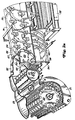
- Figure 1 shows a self-propelled combine 10 with a support frame 12 which is supported on the ground by wheels 14 and is moved by them.
- the wheels 14 are rotated by means of a drive means, not shown, to the combine 10 z. B. to move across the field.
- a crop recovery device 16 is connected to the front end region of the combine 10 in order to harvest crop from the field and to feed it threshing and separating means 18 upwards and backwards by means of an inclined conveyor.
- the threshing and separating means contain a transversely arranged threshing drum 20 and a threshing basket 21 assigned to it, to which the harvested crop is first fed.
- the threshed material is then fed to a scraper roller 23 and a turning drum 22, from where it enters an axial separator 24.
- Grain and chaff which are separated during the threshing process, fall onto at least one screw 30, which both feeds to a preparation floor 33.
- Grain and chaff which on the other hand emerge from the axial separator 24, fall onto a shaking tray 32, which leads it to be passed on to the preparation tray 33.
- the preparation floor 33 passes the grain and chaff on to a sieve box 34 associated with a blower 36 to aid in separating the chaff from the grain.
- Cleaned grain is fed by means of a grain screw 38 to an elevator, not shown, which conveys it into a grain tank 40.
- a return auger 42 returns un-threshed ear parts to the threshing process through a further elevator, not shown.
- the cleaned grain is unloaded from the grain tank 40 by an unloading system with cross screws 44 and an unloading conveyor 46.
- All of the aforementioned various systems are driven by an internal combustion engine 48, which is operated by an operator from a driver's cab 50.
- the various devices for threshing, conveying, cleaning and separating are located within the support frame 12.
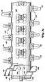
- FIGS. 2a and 2b The design of the axial separator 24 is best shown in FIGS. 2a and 2b.
- the threshing drum 20 and the concave 21 associated therewith are studded, as is provided for threshing rice; however, this version can also be exchanged for one used for threshing other crops.
- the scraper roller 23 and the turning drum 22, together with a feed housing 52 feed the threshed crop from the threshing drum 20 and the concave 21 to the axial separator 24.
- the formation of the feed housing 52 is best taught in US-A-4,611,605, the contents of which are hereby incorporated.
- the feed zone for both units of the axial separator 24 extends from a front cross plate 54 to one rear cross plate 56 and is provided with a closed bottom 58.
- Spiral guide rails 60 which are shown in broken lines, extend upward from the closed base 58 and move the threshed material backwards into a separation zone.
- the rotor is equipped with rigidly attached tines 62, which are shorter than tines 78, which are located in the separation zone of the axial separator 24. These tines 62 are shorter so that they create space for the upwardly extending guide rails 60.
- as many tines 62 are again provided on the linear length of the rotor as are found in the deposition zone.
- a cover 64 in the feed zone is equipped with downwardly directed guide rails 66 which move the threshed material to the rear within the feed zone.
- a divider plate 67 is provided within the feed zone between the two rotors and includes a vertically oriented, leading, cylindrical edge 68 and a rearwardly extending plate 69.
- the separating zone extends from the rear transverse plate 56 to a fourth transverse plate 70.
- the bottom region of each unit of the axial separator 24 is provided in the separating zone with a separating grate, which is composed of finger grids 72 and closed plates 73.
- Each finger grate 72 is designed like a rake or comb, while the closed plates 73 are metal plates, each of which covers an area of the separating grate.
- the formation of the finger grids 72 is best described in US-A-4,875,891, the content of which is hereby incorporated. Grain and chaff, which have been separated from the crop in the separation zone, fall through the finger grids 72 onto the shaker base 32.
- Upper cover plates 74 for the separation zone are equipped with inwardly extending spiral guide rails or skids 76 for moving the material to the rear. Because the bottom area in the separation zone is not equipped with spiral guide rails 76, the tines 78, which are also rigidly fastened there, are longer than the tines 62.
- a delivery zone extends from the fourth cross plate 70 to a rear cross plate 80.
- the bottom of each unit of the axial separator 24 is open at the bottom in the region of the delivery zone, so that straw can be delivered to the floor or to a straw chopper or straw spreader.
- the cover over the delivery zone is an extension of the upper cover plate 74 and is also equipped with spiral guide rails 76.
- the rotor is equipped with two longitudinally extending paddles 82 in the delivery zone.
- Each of the paddles 82 is formed from a rubber strip 84, to which wear strips 86 and a fastening strip 87 are attached.
- the wear strips 86 and the fastening strip 87 are attached to the rubber strip 84 by means of screws or rivets 89.
- the fastening strips 87 are in turn welded onto a rotor tube 100.
- the axial separator 24 is provided with a device 88 which serves to easily remove it from the combine 10 and which is best disclosed in US-A-4,969,853, the content of which is hereby incorporated by reference.
- Each of the rotors is driven by a gearbox, which is located at the rear end of the axial separator 24.
- a drive pulley 90 guides the drive into a transverse shaft that drives the two gears.
- the drive system for the two rotors is best described in US-A-4,739,773, the content of which is also hereby incorporated.
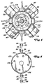
- the rotor is best shown in Figures 3a, 3b, 4 and 5 and includes the hollow cylindrical rotor tube 100 with a front end plate 102 welded into its front end and a rear end plate 104 welded into its rear end. Both end plates 102, 104 are provided with open slots 106 which allow paint to exit the rotor tube 100 after it has been immersed in a paint bath. Prong fasteners 108 are secured to the length of the rotor tube 100 in a spiral arrangement thereon. The preferred configurations of tine attachment devices 108 and tines 62, 78 are best shown in FIGS. 11 and 12 and are described in detail below with respect to these figures.
- the rear end plate 104 is provided with a gear assembly 118 which includes an internally toothed fitting 120 in which the output shaft of the gearbox mounted on the rear end of the axial separator 24 can be received.
- Each adapter 120 carries radially extending webs 122 which extend outward from adapter 120 to bushings 124.
- a rubber-like, annular insert 126 is present in each sleeve 124 and surrounds a metal sleeve 128. These metal sleeves 128 are screwed onto the rear end plate 104 by means of screws 130.
- the front end plate 102 is equipped with a screen 132 which is welded to it to prevent chaff and dirt from entering the interior of the rotor tube 100 through the slots 106.
- a second end plate 107 identical to the first front end plate 102, is inside the rotor tube 100 behind the front end plate 102 attached.
- a stub shaft 134 is welded to both front end plates 102, 107 and extends axially outward from the rotor tube 100.
- the stub shaft 134 is inserted into a bearing assembly located in the front cross plate 54.
- a radially inwardly extending ring 136 is welded to the rotor tube 100 and has chord-shaped openings 138 which correspond to the slots 106 and also serve to allow paint to leak out of the interior of the rotor tube 100.
- the inner diameter of an inner edge 140 of the ring 136 is slightly larger than the outer diameter of a cylindrical tube, not shown, which extends axially from the front cross plate 54 into the interior of the rotor tube 100.
- the resulting narrow, annular gap between the cylindrical tube of the front cross plate 54 and the inner edge 140 of the ring 136 also prevents chaff, dust and other contaminants from entering the rotor tube 100.
- Two flat metal parts 142 are close to the stub shaft 134 and welded in front of the screen 132. These metal parts 142 act like a fan and push air out through the gap between the ring 136 and the cylindrical tube, not shown.
- Balancing bores 144 are made in the two front end plates 102 and 107 and in the rear end plate 104 and are used to screw balancing weights onto the rotor tubes 100 in order to balance them.
- Rigid metal paddles 146 are fixed in the front end region of the rotor tube 100 in the region of the feed zone.
- the metal paddles 146 are screwed onto paddle holding devices 147, which in turn are welded back onto the rotor tube 100.
- the metal paddles 146 are used to to pull the crop into the feed zone of the axial separator 24.
- These metal paddles 146 are as slim as the tines 78, ie they have the same radial extension.
- the guide rails 60 which extend in a spiral and upward, therefore likewise do not extend below the metal paddles 146.
- the frame for each housing of the units of the axial separator 24 is composed of left and right axially extending hollow profiles 150, a central axial tube 152, the transverse plates 54, 56, 70, 80, a third transverse plate 154, inner side walls 178, which are diamond-shaped Form environment 180, and a fixed cover 182 is formed.
- This frame is welded together and forms the main support assembly for the axial separator 24.
- the feed zone between the cross plates 54 and 56 is provided with a closed bottom 58.
- This bottom 58 is formed from sheet metal which is screwed onto the transverse plates 54 and 56, the hollow profiles 150 and the axial tube 152.
- the separating grate is accommodated in the separating zone and contains pivotable grids or grids on which the finger grids 72 and the closed plates 73 are detachably fastened. These grids are provided between the second and third cross plates 56 and 154 and between the third and fourth cross plates 154 and 70.
- the transversely extending sections of the grids are formed by curved, part-circular cross pieces 156. Angle pieces 158 extend between the cross pieces 156 and are welded to them.
- Each unit of the axial separator 24 is provided with two grids - a front grille that extends between the transverse plates 56 and 154 and a rear grille that extends between the transverse plates 154 and 70.
- the grids pivot about axially extending pivot tubes 157 that extend through the cross plates 56, 154, 70.
- a first special U-iron 160 is welded to the bent cross pieces 156 and provided with a semicircular section 162 which overlaps a swivel tube 157.
- the U-iron 160 also has retaining screws 164, the screw head of which rests on the swivel tube 157 and forms a good fit for the grille.
- a second special steel profile 165 is also welded to the cross pieces 156 and forms part of a lattice adjustment assembly 166 which includes a bracket 168 which is in turn welded to the hollow profile 150. These brackets 168 are relatively short and do not extend over the axial length of the axial separator 24. As can be seen from FIG. 6, the right-hand unit of the axial separator 24 in the drawing is provided with a fastening screw 170 which extends through the bracket 168 second special steel profile 165, a spacer 174 and a washer 175 extends. Since the spacer 174 is located below the steel profile 165, the grid comes close to a circular line 176, which is defined by the rotating rotor.
- a narrow gap between the rotor and the grid is particularly desirable when threshing small grains such as rice.
- a large distance is desired, which can be achieved by arranging the spacer 174 above the steel profile 165, as is shown in the unit of the axial separator 24 on the left in FIG. It should be noted that the different representation of the left and right units of the axial separator 24 has been chosen for corn or small fruits only for the sake of clarity.
- the inner side walls 178 of the units of the axial separator 24 are formed from sheet metal and welded to the axial tube 152.
- the sheets of the side walls 178 extend upward into the diamond-shaped environment 180 and come together there to form a central, longitudinally extending collar 181 along the top of the axial separator 24.
- the rear area of the axial separator 24 is provided with the fixed cover 182, which has two flat caps 184.
- the flat caps 184 are designed to conform to a work platform 190 (FIG. 1).
- the axial separator 24 is provided with six cover parts, three for each unit. These cover parts are best shown in FIG. 7 and provided with semicircular sheet metal covering parts to which the guide rails 66, 76 are attached. As already in FIG. 6, the upper unit in FIG. 7 for maize and the lower unit for small goods, such as rice, are only adapted for better illustration.
- the front upper covers 64 are of the same design for all goods.
- the inner sides of the upper covers 64 are equipped with spiral guide rails 66 in order to guide the crop backwards into the units of the axial separator 24.
- the arrangement and alignment of these guide rails 66 is important in order to obtain a good, undisturbed flow of material into the units of the axial separator 24.
- a first one Guardrail 200 has a first section 202 which is arranged at an angle of approximately 30 degrees and a second section 204 which is arranged at an angle of 45 degrees to a transverse axis.
- Another three guide rails 206, 208 and 210 are also arranged at an angle of 30 degrees to the transverse axis.
- a cover flange 212 is welded to the front of the fixed cover 182 to provide a cover for the adjacent edge of the adjacent upper cover plate 74 directly in front of the fixed cover 182.
- the next two upper cover plates 74 following the cover 64 are the same for both units of the axial separator 24, but are formed depending on the crops.
- the cover plates 74 for the unit of the axial separator 24 shown in FIG. 7 below and suitable for the one type of fruit carry guide rails 76 which are aligned at an angle of approximately 20 degrees to the transverse axis. This 20 degree slope is best for threshing small fruits such as rice.
- the guide rails 76 of the cover plates 74 of the unit shown above in the drawing are arranged at an angle of 10 degrees to the transverse axis, which is best suited for crops such as maize.
- the transverse axis is always understood to mean an axis which extends at 90 degrees to the longitudinal axis and thus the conveying direction of the rotors.
- All four cover plates 74 are provided with two handles 214 which are welded to the tops thereof.
- the front edge of each cover plate 74 is provided with a cover flange 216 which corresponds to the cover flange 212 for covering the edge between adjacent cover plates 74 and the cover 182.
- the front covers 64 and cover plates 74 are provided with mounting flanges 220 extending outward and mounting flanges 222 extending upward.
- the outwardly extending fastening flanges 220 are screwed onto the hollow profiles 150 by means of screws 224 which extend through the hollow profiles 150.
- the upwardly extending mounting flanges 222 are connected to the collar 181 and itself by screws 226.
- the relationship between the guide rails 60, 66, 76, 200 and 206 - 210 and the tines 62 in the feed, separation and discharge zone is very important for a smooth flow of the crop through the axial separator 24.
- the steeper and lower Guide rails 200, 206, 208, 210 or their sections 202, 204 on the cover 64 and the guide rails 60 on the closed bottom 58 of the feed zone accelerate the crop backwards in order to get it moving quickly.
- the flatter guide rails 76 below the top cover plates 74 (25 degrees and 20 degrees for small fruits; 10 degrees for corn) prevent the crop from further accelerating its rearward speed. This ensures that the threshed material remains long enough in the axial separator 24 for a perfect separation.
- each separating grate is composed of finger grids 72 and closed plates 73 which are arranged on the pivotable grids.
- the arrangement of these plates 73 is important in order to ensure perfect separation without overloading the sieve box 34.
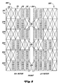
- the arrangement shown in FIG. 8 represents the best arrangement for small fruits and ensures a perfect distribution of the chaff on the sieve box 34.
- Each unit of the axial separator 24 is equipped with a separating grate with six transverse rows 300, 302, 304, 306, 308 and 310 and five openings therein. Either a finger grate 72 or a closed plate 73 are inserted into these openings. In the foremost transverse row 300, only the outermost opening is provided with a closed plate 73. The four remaining openings contain finger gratings 72 in order to allow the threshed-out material to exit to the shaking base 32.
- the next transverse row 302 has three finger gratings 72 and two closed plates 73.
- the remaining transverse rows 304-310 each have two finger gratings 72 and three closed plates 73.
- the permeable portion of the separating grate equipped with finger grids 72 is at the front, ie upstream, the largest (four finger grids 72), while it decreases evenly towards the rear up to half the distance and has only two finger grids 72 there. From half the length, the permeable portion of the area remains constant with two finger grids 72 per transverse row 306-310.
- the permeable finger grids occupy 72 70% of the first third (transverse rows 300, 302) of the Separation rust, while the closed plates occupy 30%. In the following two thirds (transverse rows 304 to 310) the finger grates 72 occupy 40% and the closed plates 73 60% of the separating grate.
- This arrangement is most effective because the threshed crop that begins to enter the axial separator 24 upstream contains a high proportion of fruit to be extracted. The further the crop is moved by the axial separator, the more this fruit content is reduced.
- FIG. 8 The representation shown in the manner of a diagram in FIG. 8 is intended for threshing small fruits.
- all closed plates 73 - except those in the outermost longitudinal rows 320, 322 - are replaced by finger grids 72.
- finger grids 72 For threshing or separating corn, all closed plates 73 - except those in the outermost longitudinal rows 320, 322 - are replaced by finger grids 72. It is also pointed out that the illustrations in FIGS. 8 and 2a, 2b do not match, since in FIG. 8 the outer openings are closed, but in FIG. 2a, 2b they are provided with finger grids 72. The representation of the finger grids 72 in FIGS. 2a, 2b has only been chosen for the sake of better representation.
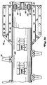
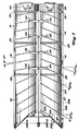
- the design of the dispensing device of the axial separator 24 is best shown in FIGS. 9 and 10.
- the delivery zone extends from the fourth cross plate 70 to the rear cross plate 80 and has an open bottom through which the crop can be discharged by means of the paddles 82.
- the first and upstream 75% of the length of the dispensing area is open and not limited by anything.
- the straw that falls through this area concentrates below the axial center line of the axial separator 24.
- the rear 25% of the discharge area is provided with a deflector 250 to deflect the straw to the outer edges of the axial separator 24, so that the straw is distributed more evenly is reached in the combine harvester 10.
- the deflector 250 is screwed to the rear cross plate 80 with screws 252 and extends forward from this in the longitudinal direction, namely over a distance of approximately a quarter of the length of the delivery area.
- the attachment of the prongs 62, 78 of the axial separator 24 on the rotor tube 100 is best shown in FIGS. 11 and 12 for both embodiments.
- the prong attachment device 108 shown is preferred for both prongs 62 and prongs 78.
- Tines 400 in general and tines 62, 78 in the feed or separation zone in particular are provided with a fastening foot 402 and a driver 404, the latter extending outwards from the fastening foot 402.
- the driver 404 extends radially outward from the rotor tube 100 and has a longitudinal, flat and flat engagement surface 406.
- the fastening foot 402 has two legs 408, each of which is provided with a fastening opening 410 into which fastening screws 412 are inserted.
- Each tine 400 is attached to a holder 414 which is welded to the rotor tube 100 at extensions 416.
- a central part 418 of the holder 414 extends upward via webs 420 from the outer surface of the rotor tube 100, i. H. radially outwards.
- a slot 422 for attaching the mounting screws 412 is machined into the center portion 418 and has an enlarged opening 424 in the center through which the head of the mounting screws 412 can be inserted. After the head of the first mounting screw 412 is inserted through the enlarged opening 424, the mounting screw 412 is moved to one end of the slot 422. The head of the second fastening screw 412 is then inserted in the same way through the opening 424 and moved to the other end of the slot 422.
- Both fastening screws 412 are then aligned with the position of the fastening openings 410 of the tine 400.
- the tines 400 are then secured on the holder 414 by means of nuts 430.
- the mounting screws 412 are of sufficient length and the slot 422 is formed such that the mounting screws 412 are held in the holder 414 and extend radially outward therefrom after being moved outward from the opening 424 along the slot 422 .
- the prong 400 is screwed onto the holder 414 and then the holder 414 is welded onto the rotor tube 100.
- the holder 414 is welded onto the rotor tube 100.
- the rotational speed of the transverse threshing drum 20 and the gap between the threshing drum 20 and the concave 21 are adjusted in a conventional manner. These settings lead the effectiveness of the threshing drum 20 with the concave 21 to a maximum with different fruits. Since the axial separator 24 is more effective than conventional straw walkers with regard to the additional separation of grain from the threshed crop, a more gentle threshing by the threshing drum 20 can be selected. At the same time, the sieve opening of the grain and short straw sieve in the sieve box 34 is optimally adjusted for the different types of fruit.
- the rotor of each unit of the axial separator 24 is accommodated in a non-concentric housing. It can be seen in the vertical section that the housing consists of a semicircular cover and a semicircular base, which are connected to one another via essentially vertical side parts. The rotor is arranged at the bottom and is equipped with tines which only engage in a relatively small part of the crop in the axial separator 24.
- the tines 400 penetrate the crop and pull it around instead of pushing it, as is typical for conventional axial threshers. This pulling prevents the crop from "rolling" and forming strands or chunks that can clamp the rotor in the housing. Due to the shape of the housing of the axial separator 24, the crop is first gripped by the tines 400, rotated and released as soon as it flies up against the guide rails 66, 76, 200, 206-210, which move the crop backwards.
- the crop is released due to the centrifugal force that lifts the crop from the tines 400 and lifts it into the space above the rotors, which is formed by the two non-concentric housings and the eccentric bearing of the rotors.
- This centrifugal force is generated when the rotor moves in a certain speed range.
- a minimum number of revolutions of 450 rpm and a maximum number of revolutions of 800 rpm are required. This results in a minimum top speed of 11.8 m / sec and a maximum top speed of 20.9 m / sec. At a speed of less than 11.8 m / sec, the crop does not detach properly from the tines 400. At a speed of more than 20.9 m / sec, the straw breakage increases.
- the minimum tip speed is a minimum peel speed, and since the tines 62 in the feed zone are shorter than the tines 78 in the separation zone, the minimum speed refers to the tines 62.
- the maximum speed prevents disproportionate grain breakage and is the maximum speed, which is permitted for the separating tines, since these are longer than the tines 62.
Description
Die Erfindung betrifft einen Axialabscheider mit wenigstens einem Rotor, der bearbeitetes Gut, insbesondere Stroh, aus einer Abgabezone abgibt, wobei das Gut einen Deflektor passiert.The invention relates to an axial separator with at least one rotor that delivers processed material, in particular straw, from a delivery zone, the material passing a deflector.
Die US-A-4,254,780 offenbart einen Mähdrescher mit einem Axialdreschsystem, an dessen abgabeseitigem Ende eine Auslaßöffnung vorgesehen ist, unterhalb der sich ein Deflektor befindet. Der Deflektor erstreckt sich über die gesamte Breite der Axialdreschvorrichtung und lenkt das aus dieser austretende Stroh, Maisspindeln oder dergleichen nach hinten ab, so daß es in einen Strohhäcksler rutschen kann. Eine gleichmäßige Verteilung des Guts über die Breite des Deflektors ist nicht gewährleistet - vielmehr wird sich das tangential abfliegende Gut nahe einer Seitenwand anlagern. Im Falle zweier Rotoren wird es je nach der Drehrichtung der Rotoren an einer gemeinsamen Abgabestelle zu einer Guthäufung kommen, die eine störungsfreie Gutannahme an einem Häcksler oder einem Strohstreuer gefährdet.US-A-4,254,780 discloses a combine harvester with an axial threshing system, at the discharge end of which there is an outlet opening below which a deflector is located. The deflector extends over the entire width of the axial threshing device and deflects the straw, corn spindles or the like emerging therefrom to the rear so that it can slip into a straw chopper. A uniform distribution of the goods over the width of the deflector is not guaranteed - rather, the tangentially flying goods will accumulate near a side wall. In the case of two rotors, depending on the direction of rotation of the rotors, there will be accumulation of goods at a common delivery point, which jeopardizes fault-free acceptance of goods on a chopper or straw spreader.
Die der Erfindung zugrunde liegende Aufgabe wird darin gesehen, einen Axialabscheider derart auszubilden, daß das in ihm bearbeitete Gut derart abgegeben wird, daß es die Funktion eines nachgeordneten Aggregats, wie etwa eines Strohhäckslers oder eines Strohstreuers nicht nachteilig beeinflußt.The object underlying the invention is seen in designing an axial separator in such a way that the material processed in it is released in such a way that it does not adversely affect the function of a downstream unit, such as a straw chopper or a straw spreader.
Diese Aufgabe wird erfindungsgemäß durch die Lehre des Patentanspruchs 1 gelöst, wobei in den weiteren Patentansprüchen Merkmale aufgeführt sind, die die Lösung in vorteilhafter Weise weiterentwickeln.According to the invention, this object is achieved by the teaching of
Auf diese Weise wird eine massive Gutansammlung in einem mittigen oder seitlichen Bereich vermieden, so daß die Gutabgabe gleichmäßig erfolgt. Der Erntegutstrom wird auf dem Weg zu der Abgabeöffnung hin zwangsläufig geteilt.In this way, a massive accumulation of goods in a central or side area is avoided, so that the goods are evenly distributed. The crop flow is inevitably divided on the way to the discharge opening.
Das Erntegut wird beim Verlassen der Rotoren an die rückwärtige Begrenzungswand, nämlich die Querplatte, geworfen und gleitet an dieser entlang der Abgabeöffnung zu. Da der Deflektor an dieser Querwand angebracht ist, trennt er jedenfalls den materialreichsten Bereich des Volumenstroms.When leaving the rotors, the crop is thrown against the rear boundary wall, namely the transverse plate, and slides there along the discharge opening. Since the deflector is attached to this transverse wall, it in any case separates the area of the volume flow with the most material.
Eine ausreichende Trennung des Gutstroms, die in einer gleichmäßigen Verteilung des Guts nach seiner Abgabe resultiert, wird bereits erreicht, wenn der Deflektor nur ca. 25 % der Länge der Abgabeöffnung einnimmt. Diese Längenbemessung stellt sicher, daß die Abgabeöffnung nicht soweit verschlossen wird, daß es zu Verstopfungen in der Abgabezone kommt.A sufficient separation of the material flow, which results in an even distribution of the material after it has been dispensed, is already achieved when the deflector takes up only approx. This length dimensioning ensures that the delivery opening is not closed to the extent that blockages occur in the delivery zone.
Die Anordnung des Deflektors zwischen zwei Rotoren in der genannten Art führt zu einer Vergleichmäßigung des Gutstroms auch bei zwei Rotoren.The arrangement of the deflector between two rotors in the manner mentioned leads to an equalization of the crop flow even with two rotors.
Eine Trennung des Guts mit einem geringen Bewegungswiderstand erfolgt bei einer Ausrichtung des Scheitels des Deflektors in der Richtung der Rotordrehachsen und somit der Haupterstreckungsrichtung einer von den Rotoren abgegebenen Erntegutmatte.The crop with a low resistance to movement is separated when the vertex of the deflector is aligned in the direction of the rotor axes of rotation and thus the main direction of extent of a crop mat emitted by the rotors.
Wenn auch verschiedene Arten eines Deflektors, z. B. mit einer ovalen, einer pyramidenähnlichen, einer runden oder einer sonstigen Form denkbar sind, so führt die Keilform doch zu der besten Trennung bei geringstem Bewegungswiderstand.Although different types of deflector, e.g. B. with an oval, a pyramid-like, a round or other shape are conceivable, the wedge shape leads to the best separation with the least movement resistance.
In der Zeichnung ist ein nachfolgend näher beschriebenes Ausführungsbeispiel der Erfindung dargestellt. Es zeigt:
- Fig. 1
- einen Mähdrescher in Seitenansicht und schematischer Darstellung mit einer quer gelagerten Dreschtrommel und einem Axialabscheider,
- Fig. 2a und 2b
- Ausschnitte eines Dreschsystems und des Axialabscheiders in perspektivischer Darstellung,
- Fig. 3a und 3b
- eine Seitenansicht eines Rotors des Axialabscheiders,
- Fig. 4
- den Rotor in Vorderansicht,
- Fig. 5
- den Rotor von hinten betrachtet,
- Fig. 6
- ein den Rotor aufnehmendes Gehäuse in einem vertikalen Schnitt durch seine Abscheidezone,
- Fig. 7
- das Gehäuse aus Fig. 6 in Draufsicht mit Angabe der Lage von Leitschienen,
- Fig. 8
- einen mit dem Gehäuse verbundenen Abscheiderost mit Angabe der Stellen, an denen Fingerroste vorgesehen oder die verschlossen sind,
- Fig. 9
- den rückwärtigen Bereich des Axialabscheiders mit einer Abgabevorrichtung in Seitenansicht,
- Fig. 10
- einen Deflektor im rückwärtigen Bereich von innen gesehen,
- Fig. 11
- eine bevorzugte Ausbildung eines Zinkens und einer Zinkenbefestigungsvorrichtung in Draufsicht und
- Fig. 12
- eine bevorzugte Ausbildung des Zinkens und der Zinkenbefestigungsvorrichtung in Vorderansicht.
- Fig. 1
- a combine in side view and schematic representation with a transverse threshing drum and an axial separator,
- 2a and 2b
- Cutouts of a threshing system and the axial separator in perspective,
- 3a and 3b
- a side view of a rotor of the axial separator,
- Fig. 4
- the rotor in front view,
- Fig. 5
- looking at the rotor from behind,
- Fig. 6
- a housing accommodating the rotor in a vertical section through its separation zone,
- Fig. 7
- 6 the housing from FIG. 6 in a top view with indication of the position of guide rails,
- Fig. 8
- a separating grate connected to the housing, indicating the locations at which finger grids are provided or which are closed,
- Fig. 9
- the rear area of the axial separator with a dispenser in side view,
- Fig. 10
- seen a deflector in the rear area from the inside,
- Fig. 11
- a preferred embodiment of a tine and a tine fastening device in plan view and
- Fig. 12
- a preferred embodiment of the tine and the tine fastening device in front view.
Figur 1 zeigt einen selbstfahrenden Mähdrescher 10 mit einem Tragrahmen 12, der sich über Räder 14 auf dem Boden abstützt und von diesen fortbewegt wird. Die Räder 14 werden mittels nicht gezeigter Antriebsmittel in Drehung versetzt, um den Mähdrescher 10 z. B. über das Feld zu bewegen. An den vorderen Endbereich des Mähdreschers 10 ist eine Erntegutbergungsvorrichtung 16 angeschlossen, um Erntegut von dem Feld zu ernten und es nach oben und hinten durch einen Schrägförderer 18 Dresch- und Abscheidemitteln zuzuführen. Die Dresch- und Abscheidemittel enthalten eine quer angeordnete Dreschtrommel 20 und einen dieser zugeordneten Dreschkorb 21, denen das geerntete Gut zuerst zugeführt wird. Danach wird das Dreschgut einer Abstreifrolle 23 und einer Wendetrommel 22 zugeführt, von wo aus es in einen Axialabscheider 24 gelangt.Figure 1 shows a self-propelled
Getreide und Spreu, die während des Dreschvorgangs abgeschieden werden, fallen auf wenigstens eine Schnecke 30, die beides einem Vorbereitungsboden 33 zuführt. Getreide und Spreu, die hingegen aus dem Axialabscheider 24 austreten, fallen auf einen Schüttelboden 32, der es zur Weitergabe auf den Vorbereitungsboden 33 führt. Der Vorbereitungsboden 33 gibt das Getreide und die Spreu einem Siebkasten 34 weiter, dem ein Gebläse 36 zugeordnet ist, um die Abscheidung der Spreu von dem Getreide zu unterstützen. Gereinigtes Getreide wird mittels einer Körnerschnecke 38 einem nicht gezeigten Elevator zugeführt, der es in einen Korntank 40 befördert. Eine Überkehrschnecke 42 gibt unausgedroschene Ährenteile durch einen weiteren nicht gezeigten Elevator zurück in den Dreschprozeß. Schließlich wird das gereinigte Getreide aus dem Korntank 40 durch ein Entladesystem mit Querschnecken 44 und einem Entladeförderer 46 entladen.Grain and chaff, which are separated during the threshing process, fall onto at least one
All die vorgenannten verschiedenen Systeme werden mittels eines Verbrennungsmotors 48 angetrieben, der von einer Bedienungsperson aus einer Fahrerkabine 50 heraus bedient wird. Die verschiedenen Vorrichtungen zum Dreschen, Fördern, Reinigen und Abscheiden befinden sich innerhalb des Tragrahmens 12.All of the aforementioned various systems are driven by an
Die Ausbildung des Axialabscheiders 24 ist am besten in den Figuren 2a und 2b gezeigt. In der dargestellten Ausführungsform sind die Dreschtrommel 20 und der dieser zugeordnete Dreschkorb 21 mit Stiften besetzt, wie dies zum Dreschen von Reis vorgesehen ist; allerdings kann diese Ausführung auch gegen eine solche ausgetauscht werden, wie sie zum Dreschen anderer Erntegüter verwendet wird. Die Abstreifrolle 23 und die Wendetrommel 22 führen gemeinsam mit einem Zufuhrgehäuse 52 das gedroschene Erntegut von der Dreschtrommel 20 und dem Dreschkorb 21 dem Axialabscheider 24 zu. Die Ausbildung des Zufuhrgehäuses 52 wird am besten in der US-A-4,611,605 gelehrt, deren Inhalt hiermit einbezogen wird.The design of the
Die Zufuhrzone für beide Einheiten des Axialabscheiders 24 erstreckt sich von einer vorderen Querplatte 54 bis zu einer rückwärtigen Querplatte 56 und ist mit einem geschlossenen Boden 58 versehen. Von dem geschlossenen Boden 58 erstrecken sich nach oben spiralförmige Leitschienen 60, die in unterbrochenen Linien dargestellt sind und das Dreschgut nach hinten in eine Abscheidezone bewegen. In der Zufuhrzone ist der Rotor mit starr befestigten Zinken 62 bestückt, die kürzer sind als Zinken 78, die sich in der Abscheidezone des Axialabscheiders 24 befinden. Diese Zinken 62 sind kürzer, damit sie Freiraum für die sich nach oben erstreckenden Leitschienen 60 schaffen. Zusätzlich sind nochmals so viele Zinken 62 auf der linearen Länge des Rotors vorgesehen, als man sie in der Abscheidezone vorfindet. Ein Deckel 64 in der Zufuhrzone ist mit nach unten gerichteten Leitschienen 66 besetzt, die das Dreschgut innerhalb der Zufuhrzone nach hinten bewegen. Ein Teilerblech 67 ist innerhalb der Zufuhrzone zwischen beiden Rotoren vorgesehen und enthält eine vertikal ausgerichtete, voreilende, zylindrische Kante 68 und eine sich nach hinten erstreckende Platte 69.The feed zone for both units of the
Die Abscheidezone erstreckt sich von der hinteren Querplatte 56 bis zu einer vierten Querplatte 70. Der Bodenbereich jeder Einheit des Axialabscheiders 24 ist in der Abscheidezone mit einem Abscheiderost versehen, der sich aus Fingerrosten 72 und geschlossenen Platten 73 zusammensetzt. Jeder Fingerrost 72 ist wie ein Rechen oder Kamm ausgebildet, während die geschlossenen Platten 73 Metallplatten sind, die jeweils einen Bereich des Abscheiderostes abdecken. Die Ausbildung der Fingerroste 72 ist am besten in der US-A-4,875, 891 beschrieben, deren Inhalt hiermit einbezogen wird. Getreide und Spreu, die aus dem Erntegut in der Abscheidezone ausgetrennt wurden, fallen durch die Fingerroste 72 auf den Schüttelboden 32. Obere Deckplatten 74 für die Abscheidezone sind mit sich nach innen erstreckenden spiralförmigen Leitschienen oder Gleitkufen 76 zum Bewegen des Materials nach hinten ausgerüstet. Da der Bodenbereich in der Abscheidezone nicht mit spiralförmigen Leitschienen 76 besetzt ist, sind die dortigen ebenfalls starr befestigten Zinken 78 länger als die Zinken 62.The separating zone extends from the rear
Eine Abgabezone erstreckt sich von der vierten Querplatte 70 bis zu einer rückwärtigen Querplatte 80. Der Boden jeder Einheit des Axialabscheiders 24 ist im Bereich der Abgabezone nach unten offen, so daß Stroh auf den Boden oder zu einem Strohhäcksler bzw. einem Strohstreuer abgegeben werden kann. Der Deckel über der Abgabezone ist eine Verlängerung der oberen Deckplatte 74 und ist ebenfalls mit spiralförmigen Leitschienen 76 bestückt. Der Rotor ist in der Abgabezone mit zwei sich längs erstrekenden Paddeln 82 bestückt. Jedes der Paddel 82 ist aus einem Gummistreifen 84 gebildet, an den Verschleißleisten 86 und eine Befestigungsleiste 87 angebracht sind. Die Anbringung der Verschleißleisten 86 und der Befestigungsleiste 87 an dem Gummistreifen 84 erfolgt mittels Schrauben oder Nieten 89. Die Befestigungsleisten 87 wiederum sind auf ein Rotorrohr 100 aufgeschweißt.A delivery zone extends from the
Der Axialabscheider 24 ist mit einer Vorrichtung 88 versehen, die dazu dient, ihn leicht aus dem Mähdrescher 10 auszubauen und die am besten in der US-A-4,969,853 offenbart ist, wobei der Inhalt dieser Schrift hiermit einbezogen wird. Jeder der Rotoren wird über je ein Getriebe angetrieben, das sich am rückwärtigen Ende des Axialabscheiders 24 befindet. Eine Antriebsscheibe 90 leitet den Antrieb in eine Querwelle, die die beiden Getriebe antreibt. Das Antriebssystem für die beiden Rotoren ist am besten in der US-A-4,739,773 beschrieben, deren Inhalt ebenfalls hiermit einbezogen wird.The
Der Rotor ist am besten in den Figuren 3a, 3b, 4 und 5 gezeigt und enthält das hohle, zylindrische Rotorrohr 100, in dessen vorderes Ende eine vordere Endplatte 102 und in dessen rückwärtiges Ende eine rückwärtige Endplatte 104 eingeschweißt ist. Beide Endplatten 102, 104 sind mit offenen Schlitzen 106 versehen, die den Austritt von Farbe aus dem Rotorrohr 100 ermöglichen, nachdem dieses in ein Farbbad getaucht worden war. Zinkenbefestigungsvorrichtungen 108 sind auf der Länge des Rotorrohrs 100 in einer spiralförmigen Anordnung auf diesem gesichert. Die bevorzugten Ausbildungen der Zinkenbefestigungsvorrichtungen 108 und der Zinken 62, 78 sind am besten in den Figuren 11 und 12 gezeigt und werden weiter unten in bezug auf diese Figuren im Detail beschrieben.The rotor is best shown in Figures 3a, 3b, 4 and 5 and includes the hollow
Die rückwärtige Endplatte 104 ist mit einem Verzahnungszusammenbau 118 versehen, der ein innenverzahntes Paßstück 120 enthält, in dem die Ausgangswelle des am rückwärtigen Ende des Axialabscheiders 24 gelagerten Getriebes aufgenommen werden kann. Jedes Paßstück 120 trägt radial verlaufende Stege 122, die sich von dem Paßstück 120 nach außen zu Büchsen 124 erstrecken. In jeder Büchse 124 ist ein gummiartiger, ringförmiger Einsatz 126 vorhanden, der eine Metallhülse 128 umgibt. Diese Metallhülsen 128 sind mittels Schrauben 130 an die rückwärtige Endplatte 104 angeschraubt.The
Die vordere Endplatte 102 ist mit einem Sieb 132 bestückt, das an sie angeschweißt ist, um den Eintritt von Spreu und Schmutz in das Innere des Rotorrohrs 100 durch die Schlitze 106 zu vermeiden.The
Eine zweite, zu der ersten vorderen Endplatte 102 identische Endplatte 107 ist innerhalb des Rotorrohrs 100 hinter der vorderen Endplatte 102 befestigt. Eine Stummelwelle 134 ist mit beiden vorderen Endplatten 102, 107 verschweißt und erstreckt sich axial von dem Rotorrohr 100 nach außen. Die Stummelwelle 134 ist in einen Lagerzusammenbau eingesetzt, der sich in der vorderen Querplatte 54 befindet. Ein sich radial nach innen erstreckender Ring 136 ist an das Rotorrohr 100 angeschweißt und weist sehnenschnittartige Öffnungen 138 auf, die mit den Schlitzen 106 übereinstimmen und ebenfalls dazu dienen, Farbe aus dem Innern des Rotorrohrs 100 auslaufen zu lassen. Der Innendurchmesser einer Innenkante 140 des Rings 136 ist geringfügig größer als der Außendurchmesser eines nicht gezeigten zylindrischen Rohrs, das sich axial von der vorderen Querplatte 54 in das Innere des Rotorrohrs 100 erstreckt. Der dadurch entstehende schmale, ringförmige Spalt zwischen dem zylindrischen Rohr der vorderen Querplatte 54 und der Innenkante 140 des Rings 136 verhindert zudem das Eindringen von Spreu, Staub und anderen Schmutzstoffen in das Rotorrohr 100. Um weiterhin die Ansammlung von Spreu, Staub und Schmutzstoffen zu verhindern, sind zwei flache Metallteile 142 auf die Stummelwelle 134 nahe und vor dem Sieb 132 aufgeschweißt. Diese Metallteile 142 wirken wie ein Gebläse und drücken Luft durch den Spalt zwischen dem Ring 136 und dem nicht gezeigten zylindrischen Rohr nach außen.A
Auswuchtbohrungen 144 sind in die beiden vorderen Endplatten 102 und 107 sowie in die rückwärtige Endplatte 104 eingebracht und werden dazu benutzt, Auswuchtgewichte an die Rotorrohre 100 zu deren Auswuchtung anzuschrauben.Balancing bores 144 are made in the two
Starre Metallpaddel 146 sind im vorderen Endbereich des Rotorrohrs 100 im Bereich der Zufuhrzone befestigt. Die Metallpaddel 146 sind an Paddelhaltevorrichtungen 147 angeschraubt, die ihrerseits wieder auf das Rotorrohr 100 aufgeschweißt sind. Die Metallpaddel 146 werden dazu benutzt, das Erntegut in die Zufuhrzone des Axialabscheiders 24 hinein zu ziehen. Diese Metallpaddel 146 sind so schlank wie die Zinken 78, d. h. sie haben die gleiche radiale Erstreckung. Die sich spiralförmig und nach oben erstreckenden Leitschienen 60 erstrecken sich daher ebenfalls nicht bis unter die Metallpaddel 146.Rigid metal paddles 146 are fixed in the front end region of the
Der Rahmen für jedes Gehäuse der Einheiten des Axialabscheiders 24 wird von linken und rechten, sich axial erstreckenden Hohlprofilen 150, einem zentralen axialen Rohr 152, den Querplatten 54, 56, 70, 80, einer dritten Querplatte 154, inneren Seitenwänden 178, die eine rautenförmige Umgebung 180 bilden, und einem festen Deckel 182 gebildet. Dieser Rahmen ist zusammengeschweißt und bildet den hauptsächlichen Tragzusammenbau für den Axialabscheider 24.The frame for each housing of the units of the
Wie bereits oben erwähnt, ist die Zufuhrzone zwischen den Querplatten 54 und 56 mit einem geschlossenen Boden 58 versehen. Dieser Boden 58 ist aus Blech gebildet, das an die Querplatten 54 und 56, die Hohlprofile 150 und das axiale Rohr 152 angeschraubt ist.As already mentioned above, the feed zone between the
Der Abscheiderost ist in der Abscheidezone untergebracht und enthält schwenkbare Gitter oder Roste, auf denen die Fingerroste 72 und die geschlossenen Platten 73 lösbar befestigt sind. Diese Gitter sind zwischen der zweiten und der dritten Querplatte 56 und 154 und zwischen der dritten und der vierten Querplatte 154 und 70 vorgesehen. Die sich quer erstreckenden Abschnitte der Gitter sind von gebogenen, teilkreisförmigen Querstücken 156 gebildet. Winkelstücke 158 erstrecken sich zwischen den Querstücken 156 und sind mit diesen verschweißt.The separating grate is accommodated in the separating zone and contains pivotable grids or grids on which the
Jede Einheit des Axialabscheiders 24 ist mit zwei Gittern versehen - einem vorderen Gitter, das sich zwischen den Querplatten 56 und 154 und einem rückwärtigen Gitter, das sich zwischen den Querplatten 154 und 70 erstreckt.Each unit of the
Die Gitter schwenken um sich axial erstreckende Schwenkrohre 157, die sich durch die Querplatten 56, 154, 70 erstrecken. Ein erstes spezielles U-Eisen 160 ist an die gebogenen Querstücke 156 geschweißt und mit einem halbkreisförmigen Abschnitt 162 versehen, der ein Schwenkrohr 157 übergreift. Das U-Eisen 160 besitzt ebenfalls Halteschrauben 164, deren Schraubenkopf an dem Schwenkrohr 157 anliegt und einen guten Paßsitz für das Gitter bildet.The grids pivot about axially extending
Ein zweites spezielles Stahlprofil 165 ist ebenfalls an die Querstücke 156 angeschweißt und bildet einen Teil eines Gittereinstellzusammenbaus 166, der eine Konsole 168 enthält, die wiederum mit dem Hohlprofil 150 verschweißt ist. Diese Konsolen 168 sind relativ kurz und erstrecken sich nicht über die axiale Länge des Axialabscheiders 24. Wie aus Figur 6 zu entnehmen ist, ist die in der Zeichnung rechte Einheit des Axialabscheiders 24 mit einer Befestigungsschraube 170 versehen, die sich durch die Konsole 168, das zweite spezielle Stahlprofil 165, ein Abstandsstück 174 und eine Scheibe 175 erstreckt. Da sich das Abstandsstück 174 unterhalb des Stahlprofils 165 befindet, kommt das Gitter nahe an eine Kreislinie 176, die von dem sich drehenden Rotor definiert wird. Ein enger Spalt zwischen dem Rotor und dem Gitter ist insbesondere beim Ausdreschen kleiner Körner, wie etwa Reis, wünschenswert. Bei Mais oder anderen Fruchtarten mit großen Körnern ist hingegen ein großer Abstand gewünscht, der dadurch erzielt werden kann, daß das Abstandsstück 174 oberhalb des Stahlprofils 165 angeordnet wird, wie dies bei der in Figur 6 links gelegenen Einheit des Axialabscheiders 24 gezeigt ist. Es wird darauf hingewiesen, daß die unterschiedliche Darstellung der linken und rechten Einheit des Axialabscheiders 24 jeweils für Mais oder kleine Früchte lediglich der Übersichtlichkeit wegen so gewählt worden ist.A second
Die inneren Seitenwände 178 der Einheiten des Axialabscheiders 24 sind aus Blech geformt und an das axiale Rohr 152 angeschweißt. Die Bleche der Seitenwände 178 erstrecken sich nach oben in die rautenförmige Umgebung 180 und gelangen dort zusammen, um einen mittigen, sich längs erstreckenden Kragen 181 entlang der Oberseite des Axialabscheiders 24 zu bilden. Der rückwärtige Bereich des Axialabscheiders 24 ist mit dem festen Deckel 182 versehen, der zwei flache Kappen 184 hat. Die flachen Kappen 184 sind so ausgebildet, daß sie sich an eine Arbeitsplattform 190 (Fig. 1) anpassen.The
Ausgehend von dem Zufuhrgehäuse 52 bis zu dem Deckel 182 ist der Axialabscheider 24 mit sechs Deckelteilen versehen, und zwar für jede Einheit drei. Diese Deckelteile sind am besten in Figur 7 gezeigt und mit halbkreisförmigen Blechbedeckungsteilen versehen, an denen die Leitschienen 66, 76 befestigt sind. Wie bereits bei Figur 6, so sind auch hier lediglich zur besseren Anschauung die in Figur 7 obere Einheit für Mais und die untere Einheit für kleine Güter, wie Reis, angepaßt.Starting from the
Die vorderen oberen Deckel 64 sind für alle Güter gleich ausgebildet. Die Innenseiten der oberen Deckel 64 sind mit spiralförmigen Leitschienen 66 bestückt, um das Erntegut nach hinten in die Einheiten des Axialabscheiders 24 zu leiten. Die Anordnung und Ausrichtung dieser Leitschienen 66 ist wichtig, um einen guten, ungestörten Materialfluß in die Einheiten des Axialabscheiders 24 zu erhalten. Eine erste Leitschiene 200 hat einen ersten Abschnitt 202, der unter einem Winkel von ca. 30 Grad, und einen zweiten Abschnitt 204, der unter einem Winkel von 45 Grad zu einer Querachse angeordnet ist. Weitere drei Leitschienen 206, 208 und 210 sind ebenfalls unter einem Winkel von 30 Grad zu der Querachse angeordnet.The front upper covers 64 are of the same design for all goods. The inner sides of the upper covers 64 are equipped with spiral guide rails 66 in order to guide the crop backwards into the units of the
Ein Deckflansch 212 ist vorne an den festen Deckel 182 angeschweißt, um eine Abdeckung für die angrenzende Kante der benachbarten oberen Deckplatte 74 direkt vor dem festen Deckel 182 zu schaffen.A
Die nächsten beiden auf die Deckel 64 folgenden, oberen Deckplatten 74 sind zwar für beide Einheiten des Axialabscheiders 24 gleich, aber abhängig von den Erntegütern ausgebildet. Die Deckplatten 74 für die in Figur 7 unten gezeichnete und für die eine Fruchtart geeignete Einheit des Axialabscheiders 24 tragen Leitschienen 76, die unter einem Winkel von ca. 20 Grad zu der Querachse ausgerichtet sind. Diese Neigung von 20 Grad ist am besten für das Dreschen von kleinen Früchten, wie etwa Reis, geeignet. Die Leitschienen 76 der Deckplatten 74 der in der Zeichnung oben gelegenen Einheit sind unter einem Winkel von 10 Grad zu der Querachse angeordnet, was am besten für Erntegüter wie Mais geeignet ist. Unter der Querachse wird stets eine Achse verstanden, die sich unter 90 Grad zu der Längsachse und somit der Förderrichtung der Rotoren erstreckt.The next two
Alle vier Deckplatten 74 sind mit zwei Handgriffen 214 versehen, die an deren Oberseiten angeschweißt sind. Zusätzlich ist die vordere Kante jeder Deckplatte 74 mit einem Deckflansch 216 versehen, der dem Deckflansch 212 zum Bedecken der Kante zwischen nebeneinander gelegenen Deckplatten 74 und dem Deckel 182 entspricht.All four
Die vorderen Deckel 64 und die Deckplatten 74 sind mit sich nach außen erstreckenden Befestigungsflanschen 220 und mit sich nach oben erstreckenden Befestigungsflanschen 222 versehen. Die sich nach außen erstreckenden Befestigungsflansche 220 sind mittels Schrauben 224, die sich durch die Hohlprofile 150 hindurch erstrecken, an die Hohlprofile 150 angeschraubt. Die sich nach oben erstreckenden Befestigungsflansche 222 sind mittels Schrauben 226 mit dem Kragen 181 und sich selbst verbunden.The front covers 64 and
Die Beziehung bzw. Zuordnung zwischen den Leitschienen 60, 66, 76, 200 und 206 - 210 und den Zinken 62 in der Zufuhr-, Abscheide- und Abgabezone ist sehr wichtig für einen einwandfreien Fluß des Ernteguts durch den Axialabscheider 24. Die steileren und unter 30 bzw. 45 Grad geneigten Leitschienen 200, 206, 208, 210 bzw. deren Abschnitte 202, 204 an dem Deckel 64 und die Leitschienen 60 an dem geschlossenen Boden 58 der Zufuhrzone beschleunigen das Erntegut nach hinten, um es schnell in Bewegung zu bringen. Die flacher angeordneten Leitschienen 76 unterhalb der oberen Deckplatten 74 (25 Grad und 20 Grad bei kleinen Früchten; 10 Grad bei Mais) hindern das Erntegut an einer weiteren Beschleunigung ihrer nach hinten gerichteten Geschwindigkeit. Dies stellt sicher, daß das Dreschgut ausreichend lang in dem Axialabscheider 24 für eine einwandfreie Abscheidung verbleibt.The relationship between the guide rails 60, 66, 76, 200 and 206 - 210 and the
Eine Bedienungsperson, die den Axialabscheider 24 von der Ausrüstung für kleine Früchte auf Mais oder umgekehrt umrüsten will, zieht den Axialabscheider 24 gemäß der US-A-4,969,853 aus dem Mähdrescher 10 nach hinten heraus und löst die Deckplatten 74 ab. Danach baut er die erforderlichen Deckplatten 74 mit den entsprechend ausgerichteten Leitschienen auf und schiebt den Axialabscheider 24 wieder in den Mähdrescher 10 hinein.An operator wishing to convert the
Wie bereits zuvor beschrieben worden ist, setzt sich jeder Abscheiderost aus Fingerrosten 72 und geschlossenen Platten 73 zusammen, die auf den schwenkbaren Gittern angeordnet sind. Beim Dreschen kleiner Früchte ist die Anordnung dieser Platten 73 wichtig, um eine einwandfreie Abscheidung ohne eine Überfrachtung des Siebkastens 34 zu gewährleisten. Die in Figur 8 gezeigte Anordnung stellt die beste Anordnung für kleine Früchte dar und sorgt für eine einwandfreie Verteilung der Spreu auf dem Siebkasten 34.As has already been described above, each separating grate is composed of
Jede Einheit des Axialabscheiders 24 ist mit einem Abscheiderost mit sechs Querreihen 300, 302, 304, 306, 308 und 310 und fünf Öffnungen darin ausgestattet. In diese Öffnungen sind entweder ein Fingerrost 72 oder eine geschlossene Platte 73 eingesetzt. In der vordersten Querreihe 300 ist lediglich die am weitesten außen gelegene Öffnung mit einer geschlossenen Platte 73 versehen. Die vier verbleibenden Öffnungen enthalten Fingerroste 72, um dem ausgedroschenen Gut einen Austritt zu dem Schüttelboden 32 zu ermöglichen. Die nächste Querreihe 302 hat drei Fingerroste 72 und zwei geschlossene Platten 73. Die verbleibenden Querreihen 304 - 310 haben jeweils zwei Fingerroste 72 und drei geschlossene Platten 73.Each unit of the
Gemäß Figur 8 ist der durchlässige und mit Fingerrosten 72 bestückte Bereichsanteil des Abscheiderostes vorne, also stromaufwärts am größten (vier Fingerroste 72), während er nach hinten bis zur halben Strecke gleichmäßig abnimmt und dort nur noch zwei Fingerroste 72 hat. Ab der halben Länge bleibt der durchlässige Bereichsanteil mit jeweils zwei Fingerrosten 72 pro Querreihe 306 - 310 konstant. Nach einer anderen Betrachtungsweise belegen die durchlässigen Fingerroste 72 70 % des ersten Drittels (Querreihen 300, 302) des Abscheiderostes, während die geschlossenen Platten 30 % belegen. In den folgenden beiden Dritteln (Querreihen 304 bis 310) belegen die Fingerroste 72 40 % und die geschlossenen Platten 73 60 % des Abscheiderostes.According to FIG. 8, the permeable portion of the separating grate equipped with
Diese Anordnung ist am wirksamsten, weil das gedroschene Erntegut, das stromaufwärts in dem Axialabscheider 24 einzutreten beginnt, einen hohen Anteil an heraus zu lösenden Früchten enthält. Je weiter das Erntegut durch den Axialabscheider bewegt wird, desto mehr verringert sich dieser Früchteanteil.This arrangement is most effective because the threshed crop that begins to enter the
Die in der Art eines Diagramms in Figur 8 wiedergegebene Darstellung ist für das Dreschen von kleinen Früchten bestimmt. Zum Dreschen bzw. Abscheiden von Mais werden alle geschlossenen Platten 73 - außer denen in den äußersten Längsreihen 320, 322 - durch Fingerroste 72 ersetzt. Es wird auch darauf hingewiesen, daß die Darstellungen der Figuren 8 und 2a, 2b nicht übereinstimmen, da in Figur 8 die äußeren Öffnungen geschlossen, in Figur 2a, 2b hingegen mit Fingerrosten 72 versehen sind. Die Darstellung der Fingerroste 72 in den Figuren 2a, 2b ist lediglich der besseren Darstellung wegen so gewählt worden.The representation shown in the manner of a diagram in FIG. 8 is intended for threshing small fruits. For threshing or separating corn, all closed plates 73 - except those in the outermost longitudinal rows 320, 322 - are replaced by
Es ist wichtig, daß das Stroh gleichmäßig verteilt wird, wenn es aus dem Axialabscheider 24 herauskommt, da dies einem nachfolgenden Strohhäcksler oder Strohstreuer einen besseren Wirkungsgrad und eine gleichmäßigere Verteilung auf dem Boden ermöglicht.It is important that the straw is evenly distributed when it comes out of the
Die Ausbildung der Abgabevorrichtung des Axialabscheiders 24 ist am besten in den Figuren 9 und 10 wiedergegeben. Die Abgabezone erstreckt sich von der vierten Querplatte 70 bis zu der rückwärtigen Querplatte 80 und hat einen offenen Boden, durch den das Erntegut mittels der Paddel 82 abgegeben werden kann. Die ersten und stromaufwärts gelegenen 75 % der Länge des Abgabebereichs sind offen und durch nichts begrenzt. Das Stroh, das durch diesen Bereich fällt, konzentriert sich unterhalb der axialen Mittellinie des Axialabscheiders 24. Die rückwärtigen 25 % des Abgabebereichs sind mit einem Deflektor 250 versehen, um das Stroh zu den außenliegenden Rändern des Axialabscheiders 24 abzulenken, damit eine gleichmäßigere Verteilung des Strohs in dem Mähdrescher 10 erreicht wird. Der Deflektor 250 ist mit Schrauben 252 an die rückwärtige Querplatte 80 angeschraubt und erstreckt sich von dieser in Längsrichtung gesehen nach vorne und zwar über eine Entfernung von ca. einem Viertel der Länge des Abgabebereichs.The design of the dispensing device of the
Die Befestigung der Zinken 62, 78 des Axialabscheiders 24 auf dem Rotorrohr 100 ist am besten in den Figuren 11 und 12 für beide Ausführungsformen dargestellt. Die dargestellte Zinkenbefestigungsvorrichtung 108 wird sowohl für die Zinken 62 als auch für die Zinken 78 bevorzugt.The attachment of the
Zinken 400 im allgemeinen und die Zinken 62, 78 in der Zufuhr- bzw. Abscheidezone im besonderen sind mit einem Befestigungsfuß 402 und einem Mitnehmer 404 versehen, wobei sich letzterer von dem Befestigungsfuß 402 aus nach außen erstreckt. Der Mitnehmer 404 erstreckt sich von dem Rotorrohr 100 radial nach außen und hat eine längs ausgerichtete, flache und ebene Eingriffsfläche 406. Der Befestigungsfuß 402 hat zwei Schenkel 408, von denen jeder mit einer Befestigungsöffnung 410 versehen ist, in die Befestigungsschrauben 412 eingesetzt sind.
Jeder Zinken 400 ist an einem Halter 414 befestigt, der an Verlängerungen 416 auf das Rotorrohr 100 geschweißt ist. Ein Mittenteil 418 des Halters 414 erstreckt sich über Stege 420 von der äußeren Oberfläche des Rotorrohrs 100 aus nach oben, d. h. radial nach außen. Ein Schlitz 422 zum Festlegen der Befestigungsschrauben 412 ist in den Mittenteil 418 eingearbeitet und enthält in seiner Mitte eine vergrößerte Öffnung 424, durch die der Kopf der Befestigungsschrauben 412 eingefügt werden kann. Nachdem der Kopf der ersten Befestigungsschraube 412 durch die vergrößerte Öffnung 424 eingeführt worden ist, wird die Befestigungsschraube 412 zum einen Ende des Schlitzes 422 bewegt. Anschließend wird der Kopf der zweiten Befestigungsschraube 412 in gleicher Weise durch die Öffnung 424 eingefügt und zum anderen Ende des Schlitzes 422 bewegt. Beide Befestigungsschrauben 412 werden dann nach der Lage der Befestigungsöffnungen 410 des Zinkens 400 ausgerichtet. Anschließend wird mittels Muttern 430 der Zinken 400 auf dem Halter 414 gesichert. Die Befestigungsschrauben 412 haben eine ausreichende Länge, und der Schlitz 422 ist so ausgebildet, daß die Befestigungsschrauben 412 in dem Halter 414 gehalten werden und sich von diesem radial nach außen erstrecken, nachdem sie von der Öffnung 424 entlang des Schlitzes 422 nach außen bewegt worden sind.Each
Zum ersten Zusammenbau des Rotors wird der Zinken 400 auf den Halter 414 geschraubt und anschließend der Halter 414 auf das Rotorrohr 100 aufgeschweißt. Infolge der zunächst vorgenommenen Montage des Zinkens 400 auf den Halter 414 werden Belastungen vermieden, die ansonsten beim nachträglichen Aufschrauben des Zinkens 400 auf den Halter 414 entstehen könnten.For the first assembly of the rotor, the
Die Drehgeschwindigkeit der quer angeordneten Dreschtrommel 20 und der Spalt zwischen der Dreschtrommel 20 und dem Dreschkorb 21 werden auf herkömmliche Weise eingestellt. Diese Einstellungen führen die Wirksamkeit der Dreschtrommel 20 mit dem Dreschkorb 21 zu einem Maximum bei unterschiedlichen Früchten. Da der Axialabscheider 24 hinsichtlich der zusätzlichen Abscheidung von Getreide aus dem gedroschenen Erntegut wirksamer ist als herkömmliche Strohschüttler, kann ein schonenderer Ausdrusch durch die Dreschtrommel 20 gewählt werden. Gleichzeitig wird die Sieböffnung des Körner- und des Kurzstrohsiebs in dem Siebkasten 34 für die unterschiedlichen Fruchtarten optimal eingestellt.The rotational speed of the
Gemäß Figur 6 ist der Rotor jeder Einheit des Axialabscheiders 24 in einem nicht-konzentrischen Gehäuse untergebracht. Man kann dort im Vertikalschnitt erkennen, daß das Gehäuse aus einem halbkreisförmigen Deckel und einem ebenfalls halbkreisförmigen Boden besteht, die miteinander über im wesentlichen vertikale Seitenteile verbunden sind. Der Rotor ist dem Boden zu angeordnet und mit Zinken bestückt, die nur in einen relativ geringen Teil in Erntegut in dem Axialabscheider 24 eingreifen.According to FIG. 6, the rotor of each unit of the
Die Zinken 400 durchdringen das Erntegut und ziehen es mit herum, anstatt es zu schieben, wie dies für herkömmliche Axialdrescher typisch ist. Dieses Ziehen verhindert, daß das Erntegut "rollt" und Stränge oder Brocken bildet, die den Rotor in dem Gehäuse festklemmen können. Aufgrund der Form des Gehäues des Axialabscheiders 24 wird das Erntegut zunächst von den Zinken 400 erfaßt, in Drehung versetzt und losgelassen, sobald es nach oben gegen die Leitschienen 66, 76, 200, 206 - 210 fliegt, die das Erntegut nach hinten bewegen.The
Das Loslassen des Ernteguts erfolgt aufgrund der Zentrifugalkraft, die das Erntegut von den Zinken 400 abhebt und in den Freiraum oberhalb der Rotoren hebt, der von den beiden nicht-konzentrischen Gehäusen und der exzentrischen Lagerung der Rotoren gebildet wird. Diese Zentrifugalkraft wird gebildet, wenn sich der Rotor in einem bestimmten Geschwindigkeitsbereich bewegt. Darüber hinaus ist es wichtig, keinen erhöhten Strohbruch infolge erhöhter Geschwindigkeit zu erzeugen.The crop is released due to the centrifugal force that lifts the crop from the
Bei Rotoren mit einem Durchmesser von 500 mm, der an den Spitzen der Zinken 400 in der Zufuhr- und der Abscheidezone gemessen wird, ist eine minimale Umdrehungszahl von 450 Upm und eine maximale Umdrehungszahl von 800 Upm erforderlich. Daraus ergibt sich eine minimale Spitzengeschwindigkeit von 11,8 m/sec und eine maximale Spitzengeschwindigkeit von 20,9 m/sec. Bei einer Geschwindigkeit von weniger als 11,8 m/sec löst sich das Erntegut nicht einwandfrei von den Zinken 400. Bei einer Geschwindigkeit von mehr als 20,9 m/sec erhöht sich der Strohbruch.For rotors with a diameter of 500 mm, which is measured at the tips of the
Da die minimale Spitzengeschwindigkeit eine minimale Ablösegeschwindigkeit ist, und da die Zinken 62 in der Zufuhrzone kürzer sind als die Zinken 78 in der Abscheidezone, bezieht sich die minimale Geschwindigkeit auf die Zinken 62. Die maximale Geschwindigkeit verhindert einen unverhältnismäßigen Körnerbruch und ist die maximale Geschwindigkeit, die für die Abscheidezinken zulässig ist, da diese länger sind als die Zinken 62.Since the minimum tip speed is a minimum peel speed, and since the
Claims (6)
- An axial separator (24) with at least one rotor, which delivers processed material, especially straw, at a discharge zone, wherein the material passes a deflector (250), characterized in that the deflector (250)a) engages in the stream of material and effects division into a plurality of component material streams,b) is arranged with a vertex at the top andc) is located above a discharge opening.
- An axial separator according to claim 1, characterized in that a housing receiving the rotor or rotors is closed at a downstream end by a cross plate (80) and the deflector (250) extends from the cross plate (80) towards the upstream region of the axial separator.
- An axial separator according to claim 1 or 2, characterized in that the deflector extends over about 1/4 of the length of the discharge opening.
- An axial separator according to one or more of the preceding claims, characterized in that the deflector (250) is, with two rotors, arranged between and below their axes of rotation.
- An axial separator according to one or more of the preceding claims, characterized in that the vertex line of the deflector (250) runs parallel to the axis of rotation of the rotor.
- An axial separator according to one or more of the preceding claims, characterized in that the deflector (250) is of wedge shape.
Applications Claiming Priority (2)
| Application Number | Priority Date | Filing Date | Title |
|---|---|---|---|
| US07/698,762 US5112279A (en) | 1991-05-10 | 1991-05-10 | Discharge structure for an axial separator |
| US698762 | 1991-05-10 |
Publications (3)
| Publication Number | Publication Date |
|---|---|
| EP0521280A2 EP0521280A2 (en) | 1993-01-07 |
| EP0521280A3 EP0521280A3 (en) | 1993-06-02 |
| EP0521280B1 true EP0521280B1 (en) | 1995-08-09 |
Family
ID=24806564
Family Applications (1)
| Application Number | Title | Priority Date | Filing Date |
|---|---|---|---|
| EP92108378A Expired - Lifetime EP0521280B1 (en) | 1991-05-10 | 1992-05-18 | Axial separator |
Country Status (6)
| Country | Link |
|---|---|
| US (1) | US5112279A (en) |
| EP (1) | EP0521280B1 (en) |
| AR (1) | AR248206A1 (en) |
| AU (1) | AU643613B2 (en) |
| CA (1) | CA2068133C (en) |
| DE (1) | DE59203195D1 (en) |
Families Citing this family (24)
| Publication number | Priority date | Publication date | Assignee | Title |
|---|---|---|---|---|
| US5356338A (en) * | 1993-04-26 | 1994-10-18 | Deere & Company | Axial rotor having an independently driven threshing section and separating section |
| US5688170A (en) * | 1993-07-01 | 1997-11-18 | Deere & Company | Rotary combine having a concentric infeed section and eccentric threshing and separating sections |
| AU676037B2 (en) * | 1993-07-01 | 1997-02-27 | Deere & Company | An axial flow combine having a concentric threshing section and an eccentric separation section |
| GB2356546A (en) * | 1999-11-26 | 2001-05-30 | Ford New Holland Nv | Threshing and separating unit for axial flow combines |
| US6375564B1 (en) | 1999-11-29 | 2002-04-23 | Deere & Company | Ramp segment for a combine rotor |
| US6503143B2 (en) | 2001-01-26 | 2003-01-07 | Deere & Company | Agricultural beater having replaceable blades |
| US6551186B2 (en) | 2001-06-06 | 2003-04-22 | Agco Corporation | Beater for a combine harvester |
| US7390252B1 (en) * | 2007-02-28 | 2008-06-24 | Cnh America Llc | Agricultural combine rotor with a four inlet impeller arrangement feeding a three rasp bar threshing element layout |
| DE102007030866A1 (en) * | 2007-07-03 | 2009-01-08 | Deere & Company, Moline | Crop processing unit with throughput-dependent circulation number |
| US20090111547A1 (en) * | 2007-10-31 | 2009-04-30 | Glenn Pope | Adjustable vane system for an axial flow rotor housing of an agricultural combine |
| US8021219B2 (en) | 2007-10-31 | 2011-09-20 | Deere And Company | Top cover for axial rotary combine having coned transition |
| US7762877B2 (en) * | 2007-11-29 | 2010-07-27 | Deere & Company | Tailing re-thresher rasp bar and rotor housing |
| US7717777B2 (en) * | 2007-11-29 | 2010-05-18 | Deere & Company | Adjustable rear rotor discharge flights |
| US8221202B2 (en) * | 2007-11-29 | 2012-07-17 | Deere & Company | Fully tapered rotor nose and threshing section |
| US8075377B2 (en) | 2007-11-29 | 2011-12-13 | Deere & Company | Rear rotor cone |
| US7654892B2 (en) * | 2007-11-29 | 2010-02-02 | Deere & Company | Tailings re-thresher deflector |
| DE102010037416A1 (en) * | 2010-09-09 | 2012-03-15 | Claas Selbstfahrende Erntemaschinen Gmbh | Separator unit for a combine harvester |
| DE102012106338A1 (en) * | 2012-07-13 | 2014-01-16 | Joachim Haase | Dreschtrommel and equipped with such a threshing drum mobile threshing |
| WO2015075516A1 (en) * | 2013-11-25 | 2015-05-28 | Agco Corporation | Vane arrangement in combine harvester processor |
| EP2910107A1 (en) * | 2014-02-24 | 2015-08-26 | John Deere (Tianjin) Co., Ltd | Threshing and separating device and combine harvester having the same |
| GB201503117D0 (en) * | 2015-02-25 | 2015-04-08 | Agco Int Gmbh | Crop engaging element for a combine harvester separating rotor |
| GB201503118D0 (en) | 2015-02-25 | 2015-04-08 | Agco Int Gmbh | Twin axial-flow crop processor in a combine harvester |
| US10375885B2 (en) * | 2015-09-17 | 2019-08-13 | Deere & Company | System for chopping and spreading residue |
| BE1023990B1 (en) * | 2016-03-29 | 2017-10-25 | Cnh Industrial Belgium Nv | THORNS AND SEPARATION SYSTEM FOR A HARVESTER |
Family Cites Families (26)
| Publication number | Priority date | Publication date | Assignee | Title |
|---|---|---|---|---|
| US1824632A (en) * | 1928-02-20 | 1931-09-22 | Schlayer Felix | Axial thrashing and straw reducing machine |
| US1776396A (en) * | 1928-06-06 | 1930-09-23 | Schlayer Felix | Axial thrashing machine |
| US2050631A (en) * | 1930-03-11 | 1936-08-11 | Clotilde Schlayer | Axial threshing and strawreducing machine |
| US2811158A (en) * | 1955-09-16 | 1957-10-29 | Rietmann Omar | Grain separating structure for combine |
| US2969862A (en) * | 1957-05-26 | 1961-01-31 | Allis Chalmers Mfg Co | Deflector |
| US3616800A (en) * | 1969-01-09 | 1971-11-02 | Sperry Rand Corp | Axial flow type combine with a discharge conveyor |
| DE2234567A1 (en) * | 1972-07-14 | 1974-01-31 | Josef Tenkhoff | HARVESTER |
| US4018232A (en) * | 1976-04-01 | 1977-04-19 | Sperry Rand Corporation | Material distribution means for concave of rotary combine |
| US4186753A (en) * | 1978-07-14 | 1980-02-05 | Sperry Rand Corporation | Material flow retarders |
| CA1107169A (en) * | 1978-10-31 | 1981-08-18 | White Motor Corporation Of Canada Limited | Apparatus for discharging threshed materials directly from the rotor of an axial flow combine |
| US4254730A (en) * | 1979-07-11 | 1981-03-10 | Crenshaw William S | Anchoring apparatus |
| US4408618A (en) * | 1980-06-06 | 1983-10-11 | Witzel H D | Axial flow rotary separator |
| GB8305259D0 (en) * | 1983-02-25 | 1983-03-30 | Sperry Nv | Combine harvesters |
| DE3417929C2 (en) * | 1984-05-15 | 1994-02-24 | Claas Ohg | Self-propelled combine |
| DE3429468C2 (en) * | 1984-08-10 | 1994-03-31 | Claas Ohg | Self-propelled combine |
| US4884994A (en) * | 1984-08-29 | 1989-12-05 | Deere & Company | Axial flow rotary separator |
| US4574815A (en) * | 1984-08-29 | 1986-03-11 | Deere & Company | Rotor for an axial flow rotary separator |
| US4611605A (en) * | 1984-08-29 | 1986-09-16 | Deere & Company | Axial flow rotary separator |
| US4611606A (en) * | 1984-08-29 | 1986-09-16 | Deere & Company | Feeding arrangement for an axial flow rotary separator |
| DE3535427C2 (en) * | 1985-10-04 | 1994-06-16 | Claas Ohg | Separation and cleaning device for a self-propelled combine |
| DE3542577C1 (en) * | 1985-12-02 | 1987-02-26 | Biso Bitter Gmbh & Co Kg | Combine device for distributing the chaff |
| DE3601359A1 (en) * | 1986-01-18 | 1987-07-23 | Claas Ohg | SELF-DRIVING COMBINATION |
| US4739773A (en) * | 1986-05-09 | 1988-04-26 | Deere & Company | Feeding arrangement for an axial flow rotary separator |
| US4711253A (en) * | 1986-05-19 | 1987-12-08 | Haybuster Manufacturing, Inc. | Chaff blower for combines |
| US4875891A (en) * | 1987-03-02 | 1989-10-24 | Deere & Company | Separating grate for a grain harvester |
| US4969853A (en) * | 1989-12-15 | 1990-11-13 | Deere & Company | Readily removable separator module |
-
1991
- 1991-05-10 US US07/698,762 patent/US5112279A/en not_active Expired - Lifetime
-
1992
- 1992-04-28 AU AU15238/92A patent/AU643613B2/en not_active Ceased
- 1992-05-07 CA CA002068133A patent/CA2068133C/en not_active Expired - Fee Related
- 1992-05-08 AR AR92322300A patent/AR248206A1/en active
- 1992-05-18 DE DE59203195T patent/DE59203195D1/en not_active Expired - Lifetime
- 1992-05-18 EP EP92108378A patent/EP0521280B1/en not_active Expired - Lifetime
Also Published As
| Publication number | Publication date |
|---|---|
| US5112279A (en) | 1992-05-12 |
| AU1523892A (en) | 1992-11-12 |
| AU643613B2 (en) | 1993-11-18 |
| AR248206A1 (en) | 1995-07-12 |
| EP0521280A3 (en) | 1993-06-02 |
| CA2068133A1 (en) | 1992-11-11 |
| DE59203195D1 (en) | 1995-09-14 |
| CA2068133C (en) | 1994-11-08 |
| EP0521280A2 (en) | 1993-01-07 |
Similar Documents
| Publication | Publication Date | Title |
|---|---|---|
| EP0521280B1 (en) | Axial separator | |
| EP0522268B1 (en) | Axial separator | |
| EP0522267B1 (en) | Axial separator | |
| EP0514820B1 (en) | Tooth, holder, tooth attachment device and axial separator | |
| DE2000553C3 (en) | ||
| DE2729033C2 (en) | ||
| DE2233019C2 (en) | Axial flow type harvester | |
| DE2628706C2 (en) | ||
| DE2462568C2 (en) | Harvester | |
| DE2948272C2 (en) | ||
| DE2729012C2 (en) | Axial flow type combine harvesters | |
| DE3042731C2 (en) | ||
| DE2725588C2 (en) | ||
| DE2430303B2 (en) | Combine with an axial threshing machine with a paddle wheel on the drum shaft International Harvester Co, Chicago, IU. (V.StA.) | |
| DE2132211A1 (en) | Combine harvester in axial flow design with rotating straw discharge | |
| DE3042735A1 (en) | HARVESTER | |
| DE2943840A1 (en) | HARVESTER | |
| DE3025380C2 (en) | ||
| DE2714260C2 (en) | Harvester | |
| DE102013226436A1 (en) | Inclined conveyor for a combine harvester | |
| DE2626815B2 (en) | Axial threshing machine of a combine harvester | |
| EP3369301B1 (en) | Agricultural harvester | |
| DE102020130801A1 (en) | THRESHOLD | |
| BE1021334B1 (en) | COMBINE WITH A NACHDRESCHEINRICHTUNG ARRANGED BETWEEN THE DRESCHEINRICHTUNG AND CLEANING | |
| DE102011083059B4 (en) | Threshing mechanism with an undershot delivery conveyor |
Legal Events
| Date | Code | Title | Description |
|---|---|---|---|
| PUAI | Public reference made under article 153(3) epc to a published international application that has entered the european phase |
Free format text: ORIGINAL CODE: 0009012 |
|
| AK | Designated contracting states |
Kind code of ref document: A2 Designated state(s): DE FR GB IT |
|
| PUAL | Search report despatched |
Free format text: ORIGINAL CODE: 0009013 |
|
| AK | Designated contracting states |
Kind code of ref document: A3 Designated state(s): DE FR GB IT |
|
| 17P | Request for examination filed |
Effective date: 19930604 |
|
| 17Q | First examination report despatched |
Effective date: 19940524 |
|
| GRAA | (expected) grant |
Free format text: ORIGINAL CODE: 0009210 |
|
| AK | Designated contracting states |
Kind code of ref document: B1 Designated state(s): DE FR GB IT |
|
| GBT | Gb: translation of ep patent filed (gb section 77(6)(a)/1977) |
Effective date: 19950812 |
|
| REF | Corresponds to: |
Ref document number: 59203195 Country of ref document: DE Date of ref document: 19950914 |
|
| ET | Fr: translation filed | ||
| ITF | It: translation for a ep patent filed |
Owner name: LENZI & C. |
|
| PLBE | No opposition filed within time limit |
Free format text: ORIGINAL CODE: 0009261 |
|
| STAA | Information on the status of an ep patent application or granted ep patent |
Free format text: STATUS: NO OPPOSITION FILED WITHIN TIME LIMIT |
|
| 26N | No opposition filed | ||
| REG | Reference to a national code |
Ref country code: GB Ref legal event code: IF02 |
|
| PGFP | Annual fee paid to national office [announced via postgrant information from national office to epo] |
Ref country code: GB Payment date: 20050511 Year of fee payment: 14 |
|
| PG25 | Lapsed in a contracting state [announced via postgrant information from national office to epo] |
Ref country code: GB Free format text: LAPSE BECAUSE OF NON-PAYMENT OF DUE FEES Effective date: 20060518 |
|
| PGFP | Annual fee paid to national office [announced via postgrant information from national office to epo] |
Ref country code: IT Payment date: 20060531 Year of fee payment: 15 |
|
| GBPC | Gb: european patent ceased through non-payment of renewal fee |
Effective date: 20060518 |
|
| PG25 | Lapsed in a contracting state [announced via postgrant information from national office to epo] |
Ref country code: IT Free format text: LAPSE BECAUSE OF NON-PAYMENT OF DUE FEES Effective date: 20070518 |
|
| PGFP | Annual fee paid to national office [announced via postgrant information from national office to epo] |
Ref country code: FR Payment date: 20110607 Year of fee payment: 20 |
|
| PGFP | Annual fee paid to national office [announced via postgrant information from national office to epo] |
Ref country code: DE Payment date: 20110420 Year of fee payment: 20 |
|
| REG | Reference to a national code |
Ref country code: DE Ref legal event code: R071 Ref document number: 59203195 Country of ref document: DE |
|
| PG25 | Lapsed in a contracting state [announced via postgrant information from national office to epo] |
Ref country code: DE Free format text: LAPSE BECAUSE OF EXPIRATION OF PROTECTION Effective date: 20120519 |