EP0122921B1 - Manufacture of article having undercut internal surface - Google Patents
Manufacture of article having undercut internal surface Download PDFInfo
- Publication number
- EP0122921B1 EP0122921B1 EP83903101A EP83903101A EP0122921B1 EP 0122921 B1 EP0122921 B1 EP 0122921B1 EP 83903101 A EP83903101 A EP 83903101A EP 83903101 A EP83903101 A EP 83903101A EP 0122921 B1 EP0122921 B1 EP 0122921B1
- Authority
- EP
- European Patent Office
- Prior art keywords
- elements
- tool
- article
- expander member
- cavity
- Prior art date
- Legal status (The legal status is an assumption and is not a legal conclusion. Google has not performed a legal analysis and makes no representation as to the accuracy of the status listed.)
- Expired
Links
Images


Classifications
-
- B—PERFORMING OPERATIONS; TRANSPORTING
- B21—MECHANICAL METAL-WORKING WITHOUT ESSENTIALLY REMOVING MATERIAL; PUNCHING METAL
- B21D—WORKING OR PROCESSING OF SHEET METAL OR METAL TUBES, RODS OR PROFILES WITHOUT ESSENTIALLY REMOVING MATERIAL; PUNCHING METAL
- B21D22/00—Shaping without cutting, by stamping, spinning, or deep-drawing
-
- F—MECHANICAL ENGINEERING; LIGHTING; HEATING; WEAPONS; BLASTING
- F16—ENGINEERING ELEMENTS AND UNITS; GENERAL MEASURES FOR PRODUCING AND MAINTAINING EFFECTIVE FUNCTIONING OF MACHINES OR INSTALLATIONS; THERMAL INSULATION IN GENERAL
- F16D—COUPLINGS FOR TRANSMITTING ROTATION; CLUTCHES; BRAKES
- F16D3/00—Yielding couplings, i.e. with means permitting movement between the connected parts during the drive
- F16D3/16—Universal joints in which flexibility is produced by means of pivots or sliding or rolling connecting parts
- F16D3/20—Universal joints in which flexibility is produced by means of pivots or sliding or rolling connecting parts one coupling part entering a sleeve of the other coupling part and connected thereto by sliding or rolling members
- F16D3/22—Universal joints in which flexibility is produced by means of pivots or sliding or rolling connecting parts one coupling part entering a sleeve of the other coupling part and connected thereto by sliding or rolling members the rolling members being balls, rollers, or the like, guided in grooves or sockets in both coupling parts
-
- B—PERFORMING OPERATIONS; TRANSPORTING
- B21—MECHANICAL METAL-WORKING WITHOUT ESSENTIALLY REMOVING MATERIAL; PUNCHING METAL
- B21J—FORGING; HAMMERING; PRESSING METAL; RIVETING; FORGE FURNACES
- B21J5/00—Methods for forging, hammering, or pressing; Special equipment or accessories therefor
- B21J5/06—Methods for forging, hammering, or pressing; Special equipment or accessories therefor for performing particular operations
- B21J5/12—Forming profiles on internal or external surfaces
-
- B—PERFORMING OPERATIONS; TRANSPORTING
- B21—MECHANICAL METAL-WORKING WITHOUT ESSENTIALLY REMOVING MATERIAL; PUNCHING METAL
- B21K—MAKING FORGED OR PRESSED METAL PRODUCTS, e.g. HORSE-SHOES, RIVETS, BOLTS OR WHEELS
- B21K1/00—Making machine elements
- B21K1/76—Making machine elements elements not mentioned in one of the preceding groups
- B21K1/762—Coupling members for conveying mechanical motion, e.g. universal joints
- B21K1/765—Outer elements of coupling members
Definitions
- This invention relates to manufacture of a hollow article having an internal surface of which at least part is undercut.
- the invention is particularly applicable to the manufacture of an outer member of a constant velocity ratio universal joint, the joint comprising an outer member, having a closed end and affording an internal cavity with the internal circumferential surface thereof having axially extending grooves formed therein; an inner joint member disposed within the outer joint member and having an external surface having grooves therein which face the grooves in the outer member; a plurality of balls disposed one in each pair of grooves in the joint members for torque transmission therebetween; and a cage of annular form disposed between the joint members and having apertures in which the balls are located.
- the internal circumferential surface of the outer joint member between the grooves thereof is part-spherical, as is the external surface of the inner joint member, and the cage has external and internal part-spherical surfaces which engage the part-spherical surfaces of the joint members, and the shape of the grooves and/or the part-spherical surfaces of the cage and joint members is such that when the joint is articulated the balls are caused to occupy a plane which bisects the angle between the rotational axes of the joint members.
- the grooves in the outer joint member may be undercut, by which we mean that the base of each groove is, at a position away from the free open end of the joint member, a greater radial distance from the rotational axis of the joint member than it is at the end of the member.
- the part-spherical internal surface of the outer joint member is undercut.
- the joint member cannot be completely formed by a forging or extrusion process involving a forming tool inserted axially into the joint member, if the tool is in one piece. This is because a one piece forming tool cannot be withdrawn once the undercut configuration has been established.
- a one piece tool can be used to form the internal shape of the joint member adjacent the closed end thereof, but it is then necessary to produce the undercut shape by removal of material, usually by milling followed by a grinding process to give the required surface finish.
- EP-A-0049474 discloses a forging die for providing grooves in a workpiece, specifically an outer member of a constant velocity ratio universal joint. Die parts for forming grooves are radially movable to enable them to be disengaged from the grooves which they form. However, because such die parts can only move simultaneously, the tool is not capable of forming a complete undercut internal surface.
- a tool for use in manufacture of a hollow article having an internal surface at least part of which is undercut said tool comprising a plurality of circumferentially disposed elements having portions together adapted to define an external surface having a configuration corresponding to that required in said internal surface, said elements including first elements and second elements interposed between them, characterised in that the external surface defined by said portions is substantially complete, and the arrangement is such that said portions of said first elements can be withdrawn from said article to leave a space or spaces to permit said portions of said second elements subsequently to be moved radially inwardly to dis-engage them from said undercut internal surface part and withdrawn from said article.
- a substantially complete surface we mean one in which there are no gaps or discontinuities sufficient for the material of the article to enter during the extrusion process, and in which material would have to be removed, e.g., by machining subsequently.
- the tool can be designed to have relatively few component parts and yet still define the entire shape of the internal surface of the hollow article.
- said elements of the tool together define an internal cavity into which an expander
- both the first and second elements of the tool Inward movement of the first elements of the tool prior to their withdrawal enables both the first and second elements of the tool to have an external configuration which defines an undercut part of the internal surface of the article.
- the side faces of the first elements, which contact the second elements must be parallel to one another or convergent towards the outside of the tool.
- the expander member may have a tapered portion which enters said internal cavity defined by said elements of the tool, to facilitate withdrawal of the expander member after a forming operation.
- the second elements of the tool may include cam surfaces which are engaged by the expander member, to hold the elements in engagement with the article, after the expander member has been at least partially withdrawn from said cavity, but which cam surfaces are dis-engaged upon further withdrawal of the expander member. This ensures that there is no hindrance to withdrawal of the first elements of the tool from the article after the expander member has been withdrawn from the cavity of the tool. However, even without such cam surfaces, the second elements of the tool will tend to remain in contact with the article after withdrawal of the expander member while the first elements of the tool are withdrawn.
- the tool may comprise a holder member which holds said first elements to allow for said inward movement thereof, said holder member being mounted for movement relative to said expander member, abutment means engaging said holder member when said expander member is withdrawn from said cavity, to withdraw said first elements from said article, and further abutment means engaging said second elements after further withdrawal of said expander member and disengagement thereof from said cam surfaces, to withdraw said second elements from said article, and spring means operative between said expander member and said first and second elements to return said elements to their operative positions and said expander member to said cavity.
- the invention also provides a press fitted with a tool according to the invention, and further comprising a die through which a hollow blank having the tool inside it can be pressed to form the article, and means for holding said article during withdrawal of the tool.
- FIG. 1 of the drawings shows a blank for use in making the outer member of a constant velocity ratio universal joint, by use of this invention.
- the blank comprises a hollow cup-shaped portion 10, and a spigot 11, the latter of which. will ultimately be provided with splines for torque transmission with another drive line component, e.g. a motor vehicle hub.
- the internal shape of the cup-shaped portion 10 of the blank includes a part-spherical surface portion 12 which runs into a cylindrical surface 13, and in the surfaces 12, 13 are formed axially extending circumferentially spaced grooves 14, each with an arcuate portion 15 and straight portion 16 in it's base.
- the blank includes no undercut portions, and hence can be made by conventional cold, warm or hot forging or back extrusion process using a one piece forming tool to give the internal shape to the blank, withdrawal of such a tool being possible because there is no undercut.
- the shape of the internal surface of the member is as shown in broken lines at 17, i.e. a continuation of the part-spherical surface 12, and the shape of the bottom of the grooves is entirely arcuate as shown in broken lines at 18.
- the undercut present in the finished joint member is exaggerated in Figure 1, it will be appreciated that a one piece forming tool cannot be used to make the article because it cannot be withdrawn from the finished article.
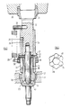
- a ram 20 of a press to which is secured, by a screw-threaded connection ring 21, a mandrel 22.
- the lower end of mandrel 22 has secured to it an elongate cylindrical expander member 23.
- a sleeve 24 is slidable longitudinally of mandrel 22, between limits determined by a peg 25 extending inwardly from sleeve 24 into a longitudinally extending slot 26 in mandrel 22.
- the collar 28 is spring biased upwardly by a plurality of tension springs 29 spaced around the collar, only one of which springs is shown in the drawing.
- the springs 29 engage pins 30 extending into mandrel 22.
- the sleeve 24 is provided with three equally circumferentially spaced radial apertures 31.
- Each aperture 31 receives a ball end of a peg 32 extending outwardly from the upper end of an element 33 having a head 34 at its lower end.
- Circumferentially spaced about sleeve 24, between the apertures 31, are three slots 35 which extend downwardly from flange 27.
- Each slot receives peg 36 extending outwardly from the upper end of an element 37 having a head 38 at its lower end.
- the pegs 36 are long enough to be engaged by collar 28.
- the head portions 34, 38 of elements 33, 37 together define an internal cavity 40 which is cylindrical and in which the expander member 23 is a close fit.
- the elements 37 have cam surfaces 39, extending above their parts defining the cavity 40.
- head portions 34, 38 of elements 33, 37 are shown diagrammatically in Figure 3 of the drawings. It will be noted that head portions 34 have parallel sides, while head portions 38 interposed therebetween are wedge shaped.
- the external shape of the head portions of the elements corresponds to the required internal configuration of the universal joint outer member, and thus each of the elements includes a protuberance which corresponds to one of the grooves of the finished joint member.
- the remainder of the exterior of the head portions of the elements 33, 37 define the part-spherical surface which is to be present in the finished joint member.
- the assembly of elements 33, 37, with the expander member 23 therein is introduced into a blank as shown in Figure 1.
- the lowermost end portions of the elements 33, 37 will fit closely within the already formed part-spherical surface 12 and grooves 14 of the blank.
- the press is then used to force the blank with thetool within itthrough a die 41. This has the effect of deforming inwardly the wall of the blank adjacent its free end, to conform to the surface shape of the assembled tool elements, as shown at 42.
- the elements 33 are now free to tilt inwardly, so that their head portions 34 adopt the positions shown in Figure 5. This tilting is possible by virtue of the ball ends of pegs 32 engaging in apertures 31. Such tilting permits the head portions to be withdrawn from the joint outer member, with continued upward movement of mandrel 22.
- the head portions 38 of elements 37 at this stage cannot be withdrawn because the expander 23 remains in engagement with their cam surfaces 39 to prevent them being displaced inwardly.
- cam surfaces 39 thereon to maintain them in position while elements 33 are moved inwardly and withdrawn may not be required.
- the apparatus is used for the manufacture of the outer member of a constant velocity ratio universal joint, it will be appreciated that it is suitable for manufacture of other components of the same general configuration, having an internal undercut surface. There may be other numbers of elements such as elements 33, 37, according to the shape of the component to be manufactured.
- the expander member 23 is cylindrical, and the cavity defined by the head portions of elements 33, 37 of the tool also is cylindrical.
- the expander member and the cavity may require to be of tapering configuration, to facilitate withdrawal of the expander member after a forming operation. If during a forming operation very high forces are developed between the contacting surfaces of the expander member and the elements of tool withdrawal of the expander member is facilitated if it is tapered. Further, for the same reason, the head portions 34 of the elements 33 of the tool may require to have sides which converge outwardly, rather than being parallel.
- the grooves in the outer jointmember are not undercut.
- the part spherical surface between the grooves is, however, still undercut.
- the tool can be used to make a joint of this type.
- the tool assembly is mounted on the ram of the press and the die is fixed on the base of the press, it would be possible for the die rather than the tool assembly to be moved by the press ram. The relative movements occurring between the parts of the tool assembly and the die would be the same.
Landscapes
- Engineering & Computer Science (AREA)
- Mechanical Engineering (AREA)
- General Engineering & Computer Science (AREA)
- Forging (AREA)
- Moulds For Moulding Plastics Or The Like (AREA)
Applications Claiming Priority (2)
| Application Number | Priority Date | Filing Date | Title |
|---|---|---|---|
| GB8229391 | 1982-10-14 | ||
| GB8229391 | 1982-10-14 |
Publications (2)
| Publication Number | Publication Date |
|---|---|
| EP0122921A1 EP0122921A1 (en) | 1984-10-31 |
| EP0122921B1 true EP0122921B1 (en) | 1987-07-08 |
Family
ID=10533597
Family Applications (1)
| Application Number | Title | Priority Date | Filing Date |
|---|---|---|---|
| EP83903101A Expired EP0122921B1 (en) | 1982-10-14 | 1983-10-03 | Manufacture of article having undercut internal surface |
Country Status (15)
| Country | Link |
|---|---|
| US (1) | US4610155A (ru) |
| EP (1) | EP0122921B1 (ru) |
| JP (1) | JPS59501857A (ru) |
| KR (1) | KR900008352B1 (ru) |
| AU (1) | AU565956B2 (ru) |
| CA (1) | CA1214928A (ru) |
| DD (1) | DD211498A5 (ru) |
| DE (1) | DE3372327D1 (ru) |
| ES (1) | ES526494A0 (ru) |
| IT (1) | IT1193446B (ru) |
| MX (1) | MX158807A (ru) |
| SU (1) | SU1657050A3 (ru) |
| WO (1) | WO1984001529A1 (ru) |
| YU (1) | YU44387B (ru) |
| ZA (1) | ZA837328B (ru) |
Families Citing this family (13)
| Publication number | Priority date | Publication date | Assignee | Title |
|---|---|---|---|---|
| GB8404321D0 (en) * | 1984-02-18 | 1984-03-21 | Pfd Ltd | Tool |
| GB8520641D0 (en) * | 1985-08-17 | 1985-09-25 | Pfd Ltd | Tool |
| DE3712301C2 (de) * | 1987-04-10 | 1994-04-28 | Loehr & Bromkamp Gmbh | Preßwerkzeug |
| JPH01104441A (ja) * | 1987-07-03 | 1989-04-21 | Aida Eng Ltd | 等速ジョイント及びその類似物の製造装置 |
| FR2649024B1 (fr) * | 1989-07-03 | 1994-05-13 | Peugeot Automobiles | Procede de fabrication d'une piece presentant une surface interne partiellement spherique et une extremite ouverte |
| JP2729852B2 (ja) * | 1990-08-07 | 1998-03-18 | 本田技研工業株式会社 | ボール継手用外輪の成形に用いられるしごき加工用ポンチの製造方法 |
| DE4214444B4 (de) * | 1992-05-06 | 2004-07-29 | Hmp Engineering Gmbh | Verfahren zur Herstellung von Kugelschalen für Gleichlaufgelenke sowie Profildorn zur Verwendung in dem Verfahren |
| US6256853B1 (en) | 2000-01-31 | 2001-07-10 | Eveready Battery Company, Inc. | Crimping die employing powered chuck |
| DE102004027950A1 (de) * | 2004-06-08 | 2006-02-16 | Ina-Schaeffler Kg | Flügelzellen-Nockenwellenversteller |
| KR101414381B1 (ko) * | 2010-03-17 | 2014-07-01 | 닛본 세이고 가부시끼가이샤 | 볼 나사, 및 볼 나사용 너트의 제조방법 |
| CN102861848A (zh) * | 2011-07-06 | 2013-01-09 | 江苏威鹰机械有限公司 | 球笼式万向节钟形壳冷锻成型凹模 |
| CN102744359A (zh) * | 2012-06-07 | 2012-10-24 | 安徽铖友汽车零部件制造有限公司 | 外球笼内腔冷挤压成型工艺 |
| CN105317861B (zh) * | 2014-07-29 | 2017-10-27 | 上海纳铁福传动系统有限公司 | 内外球笼连体锻件及其锻造模具 |
Family Cites Families (9)
| Publication number | Priority date | Publication date | Assignee | Title |
|---|---|---|---|---|
| FR1347448A (fr) * | 1963-02-06 | 1963-12-27 | Boucke & Co Gmbh | Procédé et dispositif de forgeage d'ébauches pour arbres porte-galet de directiondestinés à des voitures automobiles à partir de tronçons de barre |
| JPS5213388A (en) * | 1975-07-23 | 1977-02-01 | Hitachi Ltd | Ion analyzer |
| JPS5944138B2 (ja) * | 1975-08-20 | 1984-10-26 | エヌテ−エヌ東洋ベアリング (株) | 自在接手の外輪のしごき加工法及び装置 |
| DE2830275C3 (de) * | 1978-07-10 | 1984-02-09 | Volkswagenwerk Ag, 3180 Wolfsburg | Preßwerkzeug zur Herstellung einer Innenkontur eines vorgeformten Werkstücks |
| AT358365B (de) * | 1978-11-29 | 1980-09-10 | Ver Edelstahlwerke Ag | Schmiedegesenk |
| DE3004024C2 (de) * | 1980-02-05 | 1985-08-01 | Liebergeld, Rudolf, Dipl.-Ing., 8500 Nürnberg | Werkzeug zum Herstellen eines Gelenkkörpers |
| JPS5762831A (en) * | 1980-10-02 | 1982-04-16 | Nissan Motor Co Ltd | Forging die for part having reverse gradient |
| JPS5791837A (en) * | 1980-11-28 | 1982-06-08 | Toyota Motor Corp | Plastic working core of uniform universal joint outer ring |
| JPS57181737A (en) * | 1981-04-28 | 1982-11-09 | Aida Eng Ltd | Manufacturing device of parts with opening of reduced smaller diameter than inner part extending over whole circumference |
-
1983
- 1983-09-30 ZA ZA837328A patent/ZA837328B/xx unknown
- 1983-10-03 JP JP58503171A patent/JPS59501857A/ja active Pending
- 1983-10-03 AU AU20711/83A patent/AU565956B2/en not_active Ceased
- 1983-10-03 US US06/611,004 patent/US4610155A/en not_active Expired - Lifetime
- 1983-10-03 DE DE8383903101T patent/DE3372327D1/de not_active Expired
- 1983-10-03 EP EP83903101A patent/EP0122921B1/en not_active Expired
- 1983-10-03 WO PCT/GB1983/000245 patent/WO1984001529A1/en active IP Right Grant
- 1983-10-03 CA CA000438235A patent/CA1214928A/en not_active Expired
- 1983-10-05 MX MX199017A patent/MX158807A/es unknown
- 1983-10-13 IT IT68057/83A patent/IT1193446B/it active
- 1983-10-13 KR KR1019830004840A patent/KR900008352B1/ko not_active IP Right Cessation
- 1983-10-14 DD DD83255673A patent/DD211498A5/de not_active IP Right Cessation
- 1983-10-14 ES ES526494A patent/ES526494A0/es active Granted
- 1983-10-14 YU YU2076/83A patent/YU44387B/xx unknown
-
1984
- 1984-06-11 SU SU843749936A patent/SU1657050A3/ru active
Also Published As
| Publication number | Publication date |
|---|---|
| ES8406914A1 (es) | 1984-08-16 |
| CA1214928A (en) | 1986-12-09 |
| ZA837328B (en) | 1984-05-30 |
| YU207683A (en) | 1986-08-31 |
| JPS59501857A (ja) | 1984-11-08 |
| AU2071183A (en) | 1984-05-04 |
| AU565956B2 (en) | 1987-10-01 |
| IT8368057A0 (it) | 1983-10-13 |
| DE3372327D1 (en) | 1987-08-13 |
| IT1193446B (it) | 1988-06-22 |
| SU1657050A3 (ru) | 1991-06-15 |
| KR900008352B1 (ko) | 1990-11-17 |
| WO1984001529A1 (en) | 1984-04-26 |
| YU44387B (en) | 1990-06-30 |
| MX158807A (es) | 1989-03-15 |
| US4610155A (en) | 1986-09-09 |
| EP0122921A1 (en) | 1984-10-31 |
| KR840006297A (ko) | 1984-11-29 |
| ES526494A0 (es) | 1984-08-16 |
| DD211498A5 (de) | 1984-07-18 |
Similar Documents
| Publication | Publication Date | Title |
|---|---|---|
| EP0122921B1 (en) | Manufacture of article having undercut internal surface | |
| EP0062067B1 (en) | Manufacturing method for a tubular shell of a universal joint | |
| US6044684A (en) | Forging apparatus for inner race of constant velocity universal joint | |
| EP2000688B1 (en) | Method for producing a forged inner ring for constant velocity universal joint and manufacturing apparatus therefor | |
| US4406146A (en) | Forging die for a part with internal, tapered grooves | |
| US4843864A (en) | Press tooling for manufacturing constant velocity ratio universal joint members | |
| JPH0359777B2 (ru) | ||
| EP0153810B1 (en) | Tool for and method of making hollow articles | |
| EP0722372B1 (en) | Apparatus for forge-forming outer-ring of constant velocity joint and method thereof | |
| EP0270538B1 (en) | Tool for and method of making hollow articles | |
| GB2129354A (en) | Manufacture of article having undercut internal surface | |
| JPS6310032B2 (ru) | ||
| US5660593A (en) | Outer joint part produced as a formed plate metal part | |
| US4317356A (en) | Method of and apparatus for forging a constant-velocity ball-type universal joint | |
| US4677836A (en) | Apparatus for flanging and splining a thin-walled power transmission member | |
| JPS5844932A (ja) | 自在継手の外輪製造方法 | |
| US4741191A (en) | Method for splining and flanging thin-walled members | |
| JP3862429B2 (ja) | 等速ジョイント用内輪の製造方法および装置 | |
| JPH04356324A (ja) | スプラインシャフトの鍛造方法及び鍛造装置 | |
| US4756179A (en) | Mandrell for flanging and splining thin-walled members | |
| US4756182A (en) | Die for flanging and chamfering thin-walled members | |
| JPH04366028A (ja) | 変速用歯車 | |
| US6708549B2 (en) | Method and device for moulding a tripod spider | |
| JPH11179482A (ja) | 変速機用センターリングの成形方法 | |
| KR19990075804A (ko) | 자동차용 동력전달기어 단조성형 장치 |
Legal Events
| Date | Code | Title | Description |
|---|---|---|---|
| PUAI | Public reference made under article 153(3) epc to a published international application that has entered the european phase |
Free format text: ORIGINAL CODE: 0009012 |
|
| 17P | Request for examination filed |
Effective date: 19840619 |
|
| AK | Designated contracting states |
Designated state(s): CH DE FR LI SE |
|
| GRAA | (expected) grant |
Free format text: ORIGINAL CODE: 0009210 |
|
| AK | Designated contracting states |
Kind code of ref document: B1 Designated state(s): CH DE FR LI SE |
|
| ET | Fr: translation filed | ||
| REF | Corresponds to: |
Ref document number: 3372327 Country of ref document: DE Date of ref document: 19870813 |
|
| PLBE | No opposition filed within time limit |
Free format text: ORIGINAL CODE: 0009261 |
|
| STAA | Information on the status of an ep patent application or granted ep patent |
Free format text: STATUS: NO OPPOSITION FILED WITHIN TIME LIMIT |
|
| 26N | No opposition filed | ||
| PGFP | Annual fee paid to national office [announced via postgrant information from national office to epo] |
Ref country code: SE Payment date: 19901012 Year of fee payment: 8 |
|
| PG25 | Lapsed in a contracting state [announced via postgrant information from national office to epo] |
Ref country code: SE Effective date: 19911004 |
|
| EUG | Se: european patent has lapsed |
Ref document number: 83903101.0 Effective date: 19920510 |
|
| PGFP | Annual fee paid to national office [announced via postgrant information from national office to epo] |
Ref country code: FR Payment date: 20021008 Year of fee payment: 20 |
|
| PGFP | Annual fee paid to national office [announced via postgrant information from national office to epo] |
Ref country code: DE Payment date: 20021011 Year of fee payment: 20 |
|
| PGFP | Annual fee paid to national office [announced via postgrant information from national office to epo] |
Ref country code: CH Payment date: 20021016 Year of fee payment: 20 |
|
| PG25 | Lapsed in a contracting state [announced via postgrant information from national office to epo] |
Ref country code: LI Free format text: LAPSE BECAUSE OF EXPIRATION OF PROTECTION Effective date: 20031002 Ref country code: CH Free format text: LAPSE BECAUSE OF EXPIRATION OF PROTECTION Effective date: 20031002 |
|
| REG | Reference to a national code |
Ref country code: CH Ref legal event code: PL |