EP0153810B1 - Tool for and method of making hollow articles - Google Patents
Tool for and method of making hollow articles Download PDFInfo
- Publication number
- EP0153810B1 EP0153810B1 EP85300486A EP85300486A EP0153810B1 EP 0153810 B1 EP0153810 B1 EP 0153810B1 EP 85300486 A EP85300486 A EP 85300486A EP 85300486 A EP85300486 A EP 85300486A EP 0153810 B1 EP0153810 B1 EP 0153810B1
- Authority
- EP
- European Patent Office
- Prior art keywords
- elements
- tool
- grooves
- portions
- article
- Prior art date
- Legal status (The legal status is an assumption and is not a legal conclusion. Google has not performed a legal analysis and makes no representation as to the accuracy of the status listed.)
- Expired
Links
Images


Classifications
-
- B—PERFORMING OPERATIONS; TRANSPORTING
- B21—MECHANICAL METAL-WORKING WITHOUT ESSENTIALLY REMOVING MATERIAL; PUNCHING METAL
- B21K—MAKING FORGED OR PRESSED METAL PRODUCTS, e.g. HORSE-SHOES, RIVETS, BOLTS OR WHEELS
- B21K1/00—Making machine elements
- B21K1/76—Making machine elements elements not mentioned in one of the preceding groups
- B21K1/762—Coupling members for conveying mechanical motion, e.g. universal joints
-
- B—PERFORMING OPERATIONS; TRANSPORTING
- B21—MECHANICAL METAL-WORKING WITHOUT ESSENTIALLY REMOVING MATERIAL; PUNCHING METAL
- B21J—FORGING; HAMMERING; PRESSING METAL; RIVETING; FORGE FURNACES
- B21J5/00—Methods for forging, hammering, or pressing; Special equipment or accessories therefor
- B21J5/06—Methods for forging, hammering, or pressing; Special equipment or accessories therefor for performing particular operations
- B21J5/12—Forming profiles on internal or external surfaces
-
- B—PERFORMING OPERATIONS; TRANSPORTING
- B21—MECHANICAL METAL-WORKING WITHOUT ESSENTIALLY REMOVING MATERIAL; PUNCHING METAL
- B21K—MAKING FORGED OR PRESSED METAL PRODUCTS, e.g. HORSE-SHOES, RIVETS, BOLTS OR WHEELS
- B21K1/00—Making machine elements
- B21K1/76—Making machine elements elements not mentioned in one of the preceding groups
- B21K1/762—Coupling members for conveying mechanical motion, e.g. universal joints
- B21K1/765—Outer elements of coupling members
Definitions
- This invention relates to the manufacture of hollow articles.
- the invention has been developed for the manufacture of the outer member of a constant velocity universal joint of the cross-groove type.
- a constant velocity universal joint of the cross-groove type In such a joint, there is an inner member and an outer member, the outer member having an internal cylindrical surface and the inner member an external cylindrical surface which surfaces are grooved and there are two sets of, preferably, helical grooves in each member, the grooves of the two sets being on helices of opposite hand.
- the grooves may be straight and inclined to the rotational axis of the joint member, instead of being truly helical.
- Balls are engaged in the grooves and are held in a cage and because of the crossed configuration of the grooves the balls are held in the bisector plane of the joint as the parts of the joint articulate, to give the joint constant velocity ratio (homokinetic) properties.
- the invention has been developed for making outer members for such cross-groove constant velocity joints it is applicable generally to the manufacture of hollow articles of the type, hereinafter referred to as being of the type specified, having at least two grooves in the internal surface thereof, the grooves having longitudinal axes of symmetry (as hereinafter defined) which differ (as hereinafter defined).
- the article may have at least two sets of grooves with the grooves in each set being spaced round the longitudinal axis of the bore and having longitudinal axes of symmetry which are the same (as hereinafter defined), the longitudinal axes of symmetry of the grooves in one set being different from the longitudinal axes of symmetry of the grooves in the other set.
- longitudinal axis of symmetry of a groove we mean the imaginary line which is equally spaced from the edges of the groove and which lies in an imaginary surface forming a continuation of the bore surface and containing said edges.
- the longitudinal axes of symmetry are the same we mean that the loci of points moving in synchronism from the one ends of said axes to the other bear a fixed relation to one another.
- the longitudinal axes of symmetry differ we mean that the loci of such moving points do not lie in a fixed relation to one another.
- the axes could be on helices of different hand, or of the same hand and different pitch or on helices of different pitch and hand. Some of the axes could be straight and others could be helical.
- a tool for use in manufacture of an outer member of a constant velocity ratio universal joint comprising a number of first and second elements which together define the shape required in the interior of the joint member, and an internal cavity into which an expander fits to hold the elements in their operative positions. After removal of the expander from the cavity, the first elements can be moved radially inwardly and withdrawn from the joint member, after which the second elements can in turn be withdrawn.
- Such a tool is not applied to making an article with sets of grooves therein, the grooves in each set having longitudinal axes of symmetry which are the same as one another while the axes of symmetry of the grooves in one set are different from those of the grooves in the other set.
- the present invention provides a tool for use in manufacture of a hollow article, said tool comprising a plurality of elements having portions which are together adapted to define a substantially complete external surface having a configuration corresponding to that required in the internal surface of the article and an internal cavity into which an expander member is movable to hold said elements in positions in which they define said external surface, said elements comprising first elements and second elements interposed between them, and the arrangement being such that the expander member can be withdrawn from said cavity to permit said first elements of the tool to be moved inwardly into said cavity and said portions thereof withdrawn from said article to leave a space or spaces to permit said portions of said second elements subsequently to be moved inwardly into said space(s) to disengage them from said internal surface, and withdrawn from said article, characterised in that the tool is adapted to make an article having at least two sets of grooves in said internal surface thereof said sets of grooves having longitudinal axes of symmetry which differ such that the loci of points moving in synchronism from one end of said axes to the other do
- a substantially complete surface we mean one in which there are no gaps or discontinuities sufficient for the material of the article to enter during the forming process, and which material would have to be removed subsequently, e.g. by machining.
- the requirement for finish machining of the article can be reduced or eliminated.
- each of said portions of said first elements has a formation adapted to form one of said grooves of one set thereof, and each portion of a second element has a formation adapated to form one of said grooves of another set thereof which differs from said one set.
- the second elements may be supported by the side faces of the first elements, rather than directly by the expander member.
- Figures 1 and 2 show the outer member of a cross groove constant velocity ratio universal joint, which is a hollow article with a cylindrical internal bore having a number of grooves therein.
- the central axis of the cylindrical bore which is the rotational axis of the joint member in use, is indicated at 100.
- the joint member contains two sets of three grooves each, the grooves being of arcuate cross sectional shape and having helical longitudinal axes of symmetry.
- One set of grooves is indicated at 57, 58, 59 and these grooves are inclined in an anticlockwise helical sense when considered from above the joint member.
- the other set of grooves 60, 61, 62 are inclined in a clockwise helical sense when considered from above the joint member.
- each of the grooves is indicated by the number of the groove with the suffix letter a, such axis of symmetry lying equidistant from the edges of the groove and on the imaginary cylinder indicated by line 101, the cylinder containing the bore of the joint member.
- the grooves are machined in a blank which has been forged or extruded. Because the grooves are inclined in opposite hands, if they were formed by a one piece tool during extrusion of the article the tool would not be able to be removed from the finished article.
- the present invention provides a tool which is capable of being removed from such a joint outer member.
- FIG. 3 and 4 of the drawings there is shown a configuration of blank which may with advantage be used with the tool to be described hereafter. It is cup shaped, with its internal and external walls diverging towards its free open end.
- the internal wall 70 is of generally frusto conical form, with two sets of oppositely inclined recesses therein. One set of recesses is indicated at 71, 72, 73, inclined in one direction, and the other set at 74, 75, 76 inclined in the opposite direction.
- These recesses which are to form the grooves in the finished joint outer member, are of a configuration such that a one-piece forming tool can be withdrawn axially from the blank after the blank has been formed. Forming the blank to the finished joint outer member is achieved by inserting the tool to be described hereafter into the blank and forcing the blank through a die so as to deform the side wall of the blank inwardly as indicated by arrows 80 in Figure 4.
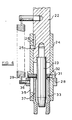
- a ram 20 of a press to which is secured, by a screw-threaded connection ring 21, a mandrel 22.
- the lower end of mandrel 22 has secured to it an elongate cylindrical expander member 23.
- a sleeve 24 is slidable longitudinally of mandrel 22, between limits determined by a peg 25 extending inwardly from sleeve 24 into a longitudinally extending slot 26 in mandrel 22.
- the collar 28 is spring biased upwardly by a plurality of tension springs 29 spaced around the collar, only one of which springs is shown in the drawing.
- the springs 29 engage pins 30 extending into the mandrel 22.
- the sleeve 24 is provided with three equally circumferentially spaced radial apertures 31.
- Each aperture 31 receives a ball end of a peg 32 extending outwardly from the upper end of an element 33 having a head 34 at its lower end.
- Circumferentially spaced about sleeve 24, between the apertures 31, are three slots 35 which extend downwardly from flange 27.
- Each slot 35 receives a peg 36 extending outwardly from the upper end of an element 37 having a head 38 at its lower end.
- the pegs 36 are long enough to be engaged by collar 28.
- the head portions 34, of elements 33, together define parts of an internal cavity 40 which is frusto conical and in which an end portion of the expander member 23 is a close fit.
- head portions 34, 38 of elements 33, 37 are shown in greater detail in Figures 8 and 9 of the drawings.
- Head portions 34 have formations 34a thereon which form the grooves of one hand, and head portions 38 have formations 38a which form the grooves of opposite hand in the joint member.
- head portions 34 have sides which are parallel or converge slightly towards the outside of the tool, while head portions 38 interposed there between are wedge shaped and are supported by the sides of head portions 34 rather than directly by contact with the end portion of the expander member.
- the assembly of elements 33, 37, with the expander member 23 therein is introduced into a blank as shown in Figures 3 and 4.
- the press is then used to force the blank with the tool within it into a die 41. This has the effect of deforming inwardly the wall of the blank adjacent its free end, to conform to the surface shape of the assembled tool elements.
- the elements 33 are now free to tilt inwardly. This tilting is possible by virtue of the ball ends of pegs 32 engaging in apertures 31. Such tilting permits the head portions to be withdrawn from the joint outer member, with continued upward movement of mandrel 22. Head portions 38 of elements 37 remain in contact with the joint outer member, supported by elements 33.
- the apparatus is used for the manufacture of the outer member of a constant velocity ratio universal joint, it will be appreciated that it is suitable for manufacture of other components of the same general configuration, having an internal surface with grooves of different hand therein. There may be other numbers of elements such as elements 33, 37, according to the shape of the component to be manufactured.
- the tool assembly is mounted on the ram of the press and the die is fixed on the base of the press, it would be possible for the die rather than the tool assembly to be moved by the press ram. The relative movements occuring between the parts of the tool assembly and the die would be the same.
Abstract
Description
- This invention relates to the manufacture of hollow articles. The invention has been developed for the manufacture of the outer member of a constant velocity universal joint of the cross-groove type. In such a joint, there is an inner member and an outer member, the outer member having an internal cylindrical surface and the inner member an external cylindrical surface which surfaces are grooved and there are two sets of, preferably, helical grooves in each member, the grooves of the two sets being on helices of opposite hand. For manufacturing simplicity, the grooves may be straight and inclined to the rotational axis of the joint member, instead of being truly helical. Balls are engaged in the grooves and are held in a cage and because of the crossed configuration of the grooves the balls are held in the bisector plane of the joint as the parts of the joint articulate, to give the joint constant velocity ratio (homokinetic) properties.
- Although the invention has been developed for making outer members for such cross-groove constant velocity joints it is applicable generally to the manufacture of hollow articles of the type, hereinafter referred to as being of the type specified, having at least two grooves in the internal surface thereof, the grooves having longitudinal axes of symmetry (as hereinafter defined) which differ (as hereinafter defined). The article may have at least two sets of grooves with the grooves in each set being spaced round the longitudinal axis of the bore and having longitudinal axes of symmetry which are the same (as hereinafter defined), the longitudinal axes of symmetry of the grooves in one set being different from the longitudinal axes of symmetry of the grooves in the other set.
- By longitudinal axis of symmetry of a groove we mean the imaginary line which is equally spaced from the edges of the groove and which lies in an imaginary surface forming a continuation of the bore surface and containing said edges.
- When we say that the longitudinal axes of symmetry are the same we mean that the loci of points moving in synchronism from the one ends of said axes to the other bear a fixed relation to one another. Conversely, when we say that the longitudinal axes of symmetry differ we mean that the loci of such moving points do not lie in a fixed relation to one another. Thus, for example, the axes could be on helices of different hand, or of the same hand and different pitch or on helices of different pitch and hand. Some of the axes could be straight and others could be helical.
- Presently in the manufacture of outer members for cross-groove constant velocity joints the blanks are made by forging, extrusion or some other metal forming method and the grooves are then machined in the bore. Such machining operations are expensive in time and equipment besides removing material. It would be convenient to be able to form the grooves in the bore without removal of metal or even to make them with imprecise grooves which would require less machining than at present. However since the longitudinal axes of symmetry of the grooves differ as defined above a one-piece tool could not be removed from the bore after the grooves had been formed.
- In published international application W084/ 01529, there is disclosed a tool for use in manufacture of an outer member of a constant velocity ratio universal joint, comprising a number of first and second elements which together define the shape required in the interior of the joint member, and an internal cavity into which an expander fits to hold the elements in their operative positions. After removal of the expander from the cavity, the first elements can be moved radially inwardly and withdrawn from the joint member, after which the second elements can in turn be withdrawn. Such a tool is not applied to making an article with sets of grooves therein, the grooves in each set having longitudinal axes of symmetry which are the same as one another while the axes of symmetry of the grooves in one set are different from those of the grooves in the other set.
- It is an object of one aspect of the invention to provide a tool for making hollow articles of the type specified and particularly for making outer members of constant velocity joints in which machining of the grooves may be reduced or eliminated.
- The present invention provides a tool for use in manufacture of a hollow article, said tool comprising a plurality of elements having portions which are together adapted to define a substantially complete external surface having a configuration corresponding to that required in the internal surface of the article and an internal cavity into which an expander member is movable to hold said elements in positions in which they define said external surface, said elements comprising first elements and second elements interposed between them, and the arrangement being such that the expander member can be withdrawn from said cavity to permit said first elements of the tool to be moved inwardly into said cavity and said portions thereof withdrawn from said article to leave a space or spaces to permit said portions of said second elements subsequently to be moved inwardly into said space(s) to disengage them from said internal surface, and withdrawn from said article, characterised in that the tool is adapted to make an article having at least two sets of grooves in said internal surface thereof said sets of grooves having longitudinal axes of symmetry which differ such that the loci of points moving in synchronism from one end of said axes to the other do not bear a fixed relation to one another, whilst the grooves in each set have axes of symmetry which are the same such that the loci of such moving points have a fixed relation to one another, said portions of said elements having formations corresponding to and adapted to form said grooves.
- By a substantially complete surface, we mean one in which there are no gaps or discontinuities sufficient for the material of the article to enter during the forming process, and which material would have to be removed subsequently, e.g. by machining. By use of the tqol according to the invention, the requirement for finish machining of the article can be reduced or eliminated.
- Preferably side faces of at least said portions of the first elements, which contact at least said portions of the second elements being parallel to one another or convergent towards the outside of the tool.
- Inward movement of the first elements of the tool prior to their withdrawal enables the elements to have formations which form the helical or inclined grooves in the bore of the article.
- Preferably each of said portions of said first elements has a formation adapted to form one of said grooves of one set thereof, and each portion of a second element has a formation adapated to form one of said grooves of another set thereof which differs from said one set.
- In their operative positions, the second elements may be supported by the side faces of the first elements, rather than directly by the expander member.
- Further details of the tool according to the invention are described hereafter.
- The invention will now be described by way of example with reference to the accompanying drawings, of which;
- Figure 1 is an end view of an outer member of a cross groove constant velocity ratio universal joint, constituting an article of the type specified.
- Figure 2 is a section through the joint outer member of Figure 1.
- Figure 3 is an end view of a blank to be used in making the joint outer member.
- Figure 4 is a section through the blank of Figure 3.
- Figure 5 is a section through part of the press in a first stage of operation.
- Figure 6 shows the press of Figure 5, in a second stage of operation.
- Figure 7 shows the press of Figures 5 and 6, in a third stage of operation.
- Figure 8 is an enlarged view of part of a tool according to the invention, in section on the line 8-8 of Figure 9.
- Figure 9 is an end view of the tool.
- Referring firstly to Figures 1 and 2, these show the outer member of a cross groove constant velocity ratio universal joint, which is a hollow article with a cylindrical internal bore having a number of grooves therein. The central axis of the cylindrical bore, which is the rotational axis of the joint member in use, is indicated at 100. The joint member contains two sets of three grooves each, the grooves being of arcuate cross sectional shape and having helical longitudinal axes of symmetry. One set of grooves is indicated at 57, 58, 59 and these grooves are inclined in an anticlockwise helical sense when considered from above the joint member. The other set of
grooves line 101, the cylinder containing the bore of the joint member. - At present, in the manufacture of constant velocity joint outer members such as these, the grooves are machined in a blank which has been forged or extruded. Because the grooves are inclined in opposite hands, if they were formed by a one piece tool during extrusion of the article the tool would not be able to be removed from the finished article. The present invention provides a tool which is capable of being removed from such a joint outer member.
- Referring now to Figures 3 and 4 of the drawings, there is shown a configuration of blank which may with advantage be used with the tool to be described hereafter. It is cup shaped, with its internal and external walls diverging towards its free open end. The
internal wall 70 is of generally frusto conical form, with two sets of oppositely inclined recesses therein. One set of recesses is indicated at 71, 72, 73, inclined in one direction, and the other set at 74, 75, 76 inclined in the opposite direction. These recesses, which are to form the grooves in the finished joint outer member, are of a configuration such that a one-piece forming tool can be withdrawn axially from the blank after the blank has been formed. Forming the blank to the finished joint outer member is achieved by inserting the tool to be described hereafter into the blank and forcing the blank through a die so as to deform the side wall of the blank inwardly as indicated byarrows 80 in Figure 4. - Referring now to Figure 5 of the drawings, there is shown a
ram 20 of a press to which is secured, by a screw-threadedconnection ring 21, amandrel 22. The lower end ofmandrel 22 has secured to it an elongatecylindrical expander member 23. Asleeve 24 is slidable longitudinally ofmandrel 22, between limits determined by apeg 25 extending inwardly fromsleeve 24 into a longitudinally extending slot 26 inmandrel 22. Towards the lower end ofsleeve 24, there is a circumferentially extendingflange 27, and slidable onsleeve 24 below theflange 27 is acollar 28. Thecollar 28 is spring biased upwardly by a plurality oftension springs 29 spaced around the collar, only one of which springs is shown in the drawing. Thesprings 29 engagepins 30 extending into themandrel 22. - Within
flange 27, thesleeve 24 is provided with three equally circumferentially spacedradial apertures 31. Eachaperture 31 receives a ball end of apeg 32 extending outwardly from the upper end of anelement 33 having ahead 34 at its lower end. Circumferentially spaced aboutsleeve 24, between theapertures 31, are threeslots 35 which extend downwardly fromflange 27. Eachslot 35 receives apeg 36 extending outwardly from the upper end of anelement 37 having ahead 38 at its lower end. Thepegs 36 are long enough to be engaged by collar 28. Thehead portions 34, ofelements 33, together define parts of aninternal cavity 40 which is frusto conical and in which an end portion of theexpander member 23 is a close fit. - The shapes of the
head portions elements Head portions 34 have formations 34a thereon which form the grooves of one hand, andhead portions 38 have formations 38a which form the grooves of opposite hand in the joint member. It will be noted thathead portions 34 have sides which are parallel or converge slightly towards the outside of the tool, whilehead portions 38 interposed there between are wedge shaped and are supported by the sides ofhead portions 34 rather than directly by contact with the end portion of the expander member. - In use of the apparatus, the assembly of
elements expander member 23 therein, is introduced into a blank as shown in Figures 3 and 4. The press is then used to force the blank with the tool within it into adie 41. This has the effect of deforming inwardly the wall of the blank adjacent its free end, to conform to the surface shape of the assembled tool elements. - The tool must then be withdrawn from the formed joint outer member, and the first stage in such withdrawal is shown in Figure 6.
- Initially, the open end of the joint outer member is engaged by suitable gripper means, not shown, to prevent its upward movement. Thereafter,
mandrel 22 is raised by operation of the press. Since theelements sleeve 24 remains in a fixed position as the mandrel is raised, untilpeg 25 abuts the lower end of slot 26. During this, springs 29 have been tensioned, while the expander member, fast withmandrel 22, has been withdrawn clear of the internal cavity of the head portions ofelements - The
elements 33 are now free to tilt inwardly. This tilting is possible by virtue of the ball ends ofpegs 32 engaging inapertures 31. Such tilting permits the head portions to be withdrawn from the joint outer member, with continued upward movement ofmandrel 22.Head portions 38 ofelements 37 remain in contact with the joint outer member, supported byelements 33. - On continued upward movement of
mandrel 22, springs 29 are tensioned further aspegs 36 onelements 37 move downslots 35, takingcollar 28 down thesleeve 24 with them. Ultimately a position as shown in Figure 7 is reached, in which pegs 36 have reached the lower ends ofslots 35 tensioning springs 29 to their fullest extent. Theelements 37 are now no longer supported byelements 33. - The condition shown in Figure 7 will not exist more than momentarily, since there will be a tendency for the
elements 37 to move inwardly as soon as their support byelements 33 ceases. However, as a consequence of the deformation of the material of the joint outer member, theelements 37 and indeed,elements 33 at an earlier stage, may adhere thereto so that an appreciable force needs to be exerted, bypegs 36 engaging bottoms ofslots 35, before theelements 37 will remove from the joint outer member. This is why the joint outer member must be engaged by some form of gripper. As soon as theelements 37 are clear of the joint outer member, springs 29 will bringcollar 28 upwardly and return, firstly, theelements 37 to their starting position. Thereafter springs 29 will bringsleeve 24 along withcollar 28 upwardly to its original position relative tomandrel 22, and the parts will then regain their relative positions illustrated in Figure 5. - Although as described the apparatus is used for the manufacture of the outer member of a constant velocity ratio universal joint, it will be appreciated that it is suitable for manufacture of other components of the same general configuration, having an internal surface with grooves of different hand therein. There may be other numbers of elements such as
elements - Although as described above the tool assembly is mounted on the ram of the press and the die is fixed on the base of the press, it would be possible for the die rather than the tool assembly to be moved by the press ram. The relative movements occuring between the parts of the tool assembly and the die would be the same.
Claims (7)
Priority Applications (1)
| Application Number | Priority Date | Filing Date | Title |
|---|---|---|---|
| AT85300486T ATE35784T1 (en) | 1984-02-18 | 1985-01-24 | TOOLS AND PROCESSES FOR MAKING HOLLOW OBJECTS. |
Applications Claiming Priority (2)
| Application Number | Priority Date | Filing Date | Title |
|---|---|---|---|
| GB8404321 | 1984-02-18 | ||
| GB848404321A GB8404321D0 (en) | 1984-02-18 | 1984-02-18 | Tool |
Publications (2)
| Publication Number | Publication Date |
|---|---|
| EP0153810A1 EP0153810A1 (en) | 1985-09-04 |
| EP0153810B1 true EP0153810B1 (en) | 1988-07-20 |
Family
ID=10556820
Family Applications (2)
| Application Number | Title | Priority Date | Filing Date |
|---|---|---|---|
| EP85300486A Expired EP0153810B1 (en) | 1984-02-18 | 1985-01-24 | Tool for and method of making hollow articles |
| EP85900708A Pending EP0201499A1 (en) | 1984-02-18 | 1985-01-24 | Tool for and method of making hollow articles |
Family Applications After (1)
| Application Number | Title | Priority Date | Filing Date |
|---|---|---|---|
| EP85900708A Pending EP0201499A1 (en) | 1984-02-18 | 1985-01-24 | Tool for and method of making hollow articles |
Country Status (12)
| Country | Link |
|---|---|
| EP (2) | EP0153810B1 (en) |
| JP (1) | JPS61501831A (en) |
| AT (1) | ATE35784T1 (en) |
| AU (1) | AU583260B2 (en) |
| BR (1) | BR8507121A (en) |
| CA (1) | CA1272371A (en) |
| DE (1) | DE3563821D1 (en) |
| ES (1) | ES8603308A1 (en) |
| GB (2) | GB8404321D0 (en) |
| MX (1) | MX162499A (en) |
| WO (1) | WO1985003655A1 (en) |
| ZA (1) | ZA85834B (en) |
Cited By (1)
| Publication number | Priority date | Publication date | Assignee | Title |
|---|---|---|---|---|
| DE4138126A1 (en) * | 1991-11-19 | 1993-05-27 | Fraunhofer Ges Forschung | Non-cutting tool to shape workpieces - has tool elements inserted into workpiece, and engaged by expander in radial direction, pressing elements against workpieces, forming threads |
Families Citing this family (9)
| Publication number | Priority date | Publication date | Assignee | Title |
|---|---|---|---|---|
| GB8520641D0 (en) * | 1985-08-17 | 1985-09-25 | Pfd Ltd | Tool |
| DE3712301C2 (en) * | 1987-04-10 | 1994-04-28 | Loehr & Bromkamp Gmbh | Press tool |
| JPH01104441A (en) * | 1987-07-03 | 1989-04-21 | Aida Eng Ltd | Manufacturing equipment for equal velocity joint and its similar item |
| DE3933293A1 (en) * | 1989-10-05 | 1991-04-11 | Schoeneweiss & Co Gmbh | SPREADING TOOL |
| DE3933292A1 (en) * | 1989-10-05 | 1991-04-11 | Schoeneweiss & Co Gmbh | SPREADING TOOL FOR A FORMING DEVICE |
| DE19832503A1 (en) * | 1998-07-20 | 2000-01-27 | Schaeffler Waelzlager Ohg | Manufacturing rotation symmetrical molded article with undercuts, slots, cavities or threading on inside, by placing removable splay sleeve inside article and then drawing it inside mold |
| JP4319015B2 (en) * | 2003-11-27 | 2009-08-26 | 本田技研工業株式会社 | Manufacturing method of outer ring member for constant velocity joint |
| US7347077B2 (en) | 2003-11-27 | 2008-03-25 | Honda Motor Co., Ltd. | Method of manufacturing outer ring member for constant velocity joint |
| CN106111863A (en) * | 2016-07-11 | 2016-11-16 | 上海纳铁福传动系统有限公司 | The processing method of a kind of forging and forging mold thereof |
Family Cites Families (9)
| Publication number | Priority date | Publication date | Assignee | Title |
|---|---|---|---|---|
| DE2830275C3 (en) * | 1978-07-10 | 1984-02-09 | Volkswagenwerk Ag, 3180 Wolfsburg | Press tool for producing an inner contour of a preformed workpiece |
| AT358365B (en) * | 1978-11-29 | 1980-09-10 | Ver Edelstahlwerke Ag | FORGED DIE |
| US4262518A (en) * | 1979-07-16 | 1981-04-21 | Caterpillar Tractor Co. | Tube expander and method |
| DE3004024C2 (en) * | 1980-02-05 | 1985-08-01 | Liebergeld, Rudolf, Dipl.-Ing., 8500 Nürnberg | Tool for producing a joint body |
| JPS571685A (en) * | 1980-05-28 | 1982-01-06 | Tokyo Shibaura Electric Co | Turning gear holding article |
| JPS57181737A (en) * | 1981-04-28 | 1982-11-09 | Aida Eng Ltd | Manufacturing device of parts with opening of reduced smaller diameter than inner part extending over whole circumference |
| FR2526687B1 (en) * | 1982-05-13 | 1985-08-30 | Luchaire Sa | FORMING AND CALIBRATION TOOL, PARTICULARLY FOR BOLS OF ROCKET JOINTS |
| ZA837329B (en) * | 1982-10-14 | 1984-05-30 | Pfd Ltd | Tool for and method of making hollow articles |
| ZA837328B (en) * | 1982-10-14 | 1984-05-30 | Pfd Ltd | Manufacture of article having undercut internal surface |
-
1984
- 1984-02-18 GB GB848404321A patent/GB8404321D0/en active Pending
-
1985
- 1985-01-24 GB GB08618146A patent/GB2183187B/en not_active Expired
- 1985-01-24 BR BR8507121A patent/BR8507121A/en unknown
- 1985-01-24 JP JP60500573A patent/JPS61501831A/en active Pending
- 1985-01-24 AT AT85300486T patent/ATE35784T1/en active
- 1985-01-24 AU AU38879/85A patent/AU583260B2/en not_active Ceased
- 1985-01-24 WO PCT/GB1985/000036 patent/WO1985003655A1/en not_active Application Discontinuation
- 1985-01-24 DE DE8585300486T patent/DE3563821D1/en not_active Expired
- 1985-01-24 EP EP85300486A patent/EP0153810B1/en not_active Expired
- 1985-01-24 EP EP85900708A patent/EP0201499A1/en active Pending
- 1985-02-04 ZA ZA85834A patent/ZA85834B/en unknown
- 1985-02-08 CA CA000473871A patent/CA1272371A/en not_active Expired - Lifetime
- 1985-02-15 MX MX204348A patent/MX162499A/en unknown
- 1985-02-18 ES ES540499A patent/ES8603308A1/en not_active Expired
Cited By (1)
| Publication number | Priority date | Publication date | Assignee | Title |
|---|---|---|---|---|
| DE4138126A1 (en) * | 1991-11-19 | 1993-05-27 | Fraunhofer Ges Forschung | Non-cutting tool to shape workpieces - has tool elements inserted into workpiece, and engaged by expander in radial direction, pressing elements against workpieces, forming threads |
Also Published As
| Publication number | Publication date |
|---|---|
| ATE35784T1 (en) | 1988-08-15 |
| DE3563821D1 (en) | 1988-08-25 |
| BR8507121A (en) | 1987-07-14 |
| ES540499A0 (en) | 1985-12-16 |
| GB2183187B (en) | 1988-06-15 |
| EP0201499A1 (en) | 1986-11-20 |
| JPS61501831A (en) | 1986-08-28 |
| ES8603308A1 (en) | 1985-12-16 |
| AU583260B2 (en) | 1989-04-27 |
| AU3887985A (en) | 1985-09-10 |
| CA1272371A (en) | 1990-08-07 |
| GB8618146D0 (en) | 1986-09-03 |
| WO1985003655A1 (en) | 1985-08-29 |
| GB2183187A (en) | 1987-06-03 |
| ZA85834B (en) | 1985-09-25 |
| MX162499A (en) | 1991-05-13 |
| GB8404321D0 (en) | 1984-03-21 |
| EP0153810A1 (en) | 1985-09-04 |
Similar Documents
| Publication | Publication Date | Title |
|---|---|---|
| EP0153810B1 (en) | Tool for and method of making hollow articles | |
| EP0121531B1 (en) | Tool for and method of making hollow articles | |
| EP2000688B1 (en) | Method for producing a forged inner ring for constant velocity universal joint and manufacturing apparatus therefor | |
| EP0049474B1 (en) | Forging die for a part with internal, tapered grooves | |
| EP0270538B1 (en) | Tool for and method of making hollow articles | |
| JPS61278467A (en) | Valve sleeve and manufacture thereof | |
| EP0122921B1 (en) | Manufacture of article having undercut internal surface | |
| JPH0341249B2 (en) | ||
| US5732586A (en) | Cold extrusion for helical gear teeth | |
| US4428220A (en) | Method and tool for the cold forging of internally profiled tubes | |
| US4843864A (en) | Press tooling for manufacturing constant velocity ratio universal joint members | |
| EP0722372B1 (en) | Apparatus for forge-forming outer-ring of constant velocity joint and method thereof | |
| EP0137580B1 (en) | Method and apparatus for drawing heavy wall shells with a multi-step inside edge | |
| US5660593A (en) | Outer joint part produced as a formed plate metal part | |
| GB2129354A (en) | Manufacture of article having undercut internal surface | |
| EP0084713B1 (en) | Crimp locator | |
| EP0158883A2 (en) | Outerrace of universal joint with cross grooves | |
| JPH0718452Y2 (en) | Punch for outer ring machining of constant velocity joint |
Legal Events
| Date | Code | Title | Description |
|---|---|---|---|
| PUAI | Public reference made under article 153(3) epc to a published international application that has entered the european phase |
Free format text: ORIGINAL CODE: 0009012 |
|
| AK | Designated contracting states |
Designated state(s): IT |
|
| 17P | Request for examination filed |
Effective date: 19860222 |
|
| 17Q | First examination report despatched |
Effective date: 19870512 |
|
| RBV | Designated contracting states (corrected) |
Designated state(s): AT BE CH DE FR GB IT LI LU NL SE |
|
| XX | Miscellaneous (additional remarks) |
Free format text: VERBUNDEN MIT 85900708.0/0201499 (EUROPAEISCHE ANMELDENUMMER/VEROEFFENTLICHUNGSNUMMER) DURCH ENTSCHEIDUNG VOM 28.08.87. |
|
| GRAA | (expected) grant |
Free format text: ORIGINAL CODE: 0009210 |
|
| AK | Designated contracting states |
Kind code of ref document: B1 Designated state(s): AT BE CH DE FR GB IT LI LU NL SE |
|
| REF | Corresponds to: |
Ref document number: 35784 Country of ref document: AT Date of ref document: 19880815 Kind code of ref document: T |
|
| XX | Miscellaneous (additional remarks) |
Free format text: VERBUNDEN MIT 85900708.0/0201499 (EUROPAEISCHE ANMELDENUMMER/VEROEFFENTLICHUNGSNUMMER) DURCH ENTSCHEIDUNG VOM 28.08.87. |
|
| ITF | It: translation for a ep patent filed |
Owner name: JACOBACCI & PERANI S.P.A. |
|
| REF | Corresponds to: |
Ref document number: 3563821 Country of ref document: DE Date of ref document: 19880825 |
|
| ET | Fr: translation filed | ||
| PLBE | No opposition filed within time limit |
Free format text: ORIGINAL CODE: 0009261 |
|
| STAA | Information on the status of an ep patent application or granted ep patent |
Free format text: STATUS: NO OPPOSITION FILED WITHIN TIME LIMIT |
|
| 26N | No opposition filed | ||
| PGFP | Annual fee paid to national office [announced via postgrant information from national office to epo] |
Ref country code: AT Payment date: 19910111 Year of fee payment: 7 |
|
| PGFP | Annual fee paid to national office [announced via postgrant information from national office to epo] |
Ref country code: SE Payment date: 19910117 Year of fee payment: 7 |
|
| PGFP | Annual fee paid to national office [announced via postgrant information from national office to epo] |
Ref country code: LU Payment date: 19910128 Year of fee payment: 7 |
|
| ITTA | It: last paid annual fee | ||
| PGFP | Annual fee paid to national office [announced via postgrant information from national office to epo] |
Ref country code: NL Payment date: 19910131 Year of fee payment: 7 |
|
| PGFP | Annual fee paid to national office [announced via postgrant information from national office to epo] |
Ref country code: BE Payment date: 19910207 Year of fee payment: 7 |
|
| EPTA | Lu: last paid annual fee | ||
| PG25 | Lapsed in a contracting state [announced via postgrant information from national office to epo] |
Ref country code: LU Free format text: LAPSE BECAUSE OF NON-PAYMENT OF DUE FEES Effective date: 19920124 Ref country code: AT Effective date: 19920124 |
|
| PG25 | Lapsed in a contracting state [announced via postgrant information from national office to epo] |
Ref country code: SE Effective date: 19920125 |
|
| PG25 | Lapsed in a contracting state [announced via postgrant information from national office to epo] |
Ref country code: BE Effective date: 19920131 |
|
| BERE | Be: lapsed |
Owner name: PFD LTD Effective date: 19920131 |
|
| PG25 | Lapsed in a contracting state [announced via postgrant information from national office to epo] |
Ref country code: NL Effective date: 19920801 |
|
| NLV4 | Nl: lapsed or anulled due to non-payment of the annual fee | ||
| EUG | Se: european patent has lapsed |
Ref document number: 85300486.9 Effective date: 19920806 |
|
| REG | Reference to a national code |
Ref country code: GB Ref legal event code: IF02 |
|
| PGFP | Annual fee paid to national office [announced via postgrant information from national office to epo] |
Ref country code: FR Payment date: 20030110 Year of fee payment: 19 |
|
| PGFP | Annual fee paid to national office [announced via postgrant information from national office to epo] |
Ref country code: GB Payment date: 20030122 Year of fee payment: 19 |
|
| PGFP | Annual fee paid to national office [announced via postgrant information from national office to epo] |
Ref country code: CH Payment date: 20030130 Year of fee payment: 19 |
|
| PGFP | Annual fee paid to national office [announced via postgrant information from national office to epo] |
Ref country code: DE Payment date: 20030206 Year of fee payment: 19 |
|
| PG25 | Lapsed in a contracting state [announced via postgrant information from national office to epo] |
Ref country code: GB Free format text: LAPSE BECAUSE OF NON-PAYMENT OF DUE FEES Effective date: 20040124 |
|
| PG25 | Lapsed in a contracting state [announced via postgrant information from national office to epo] |
Ref country code: LI Free format text: LAPSE BECAUSE OF NON-PAYMENT OF DUE FEES Effective date: 20040131 Ref country code: CH Free format text: LAPSE BECAUSE OF NON-PAYMENT OF DUE FEES Effective date: 20040131 |
|
| PG25 | Lapsed in a contracting state [announced via postgrant information from national office to epo] |
Ref country code: DE Free format text: LAPSE BECAUSE OF NON-PAYMENT OF DUE FEES Effective date: 20040803 |
|
| GBPC | Gb: european patent ceased through non-payment of renewal fee |
Effective date: 20040124 |
|
| REG | Reference to a national code |
Ref country code: CH Ref legal event code: PL |
|
| PG25 | Lapsed in a contracting state [announced via postgrant information from national office to epo] |
Ref country code: FR Free format text: LAPSE BECAUSE OF NON-PAYMENT OF DUE FEES Effective date: 20040930 |
|
| REG | Reference to a national code |
Ref country code: FR Ref legal event code: ST |