EP0122331B1 - Répondeur téléphonique automatique - Google Patents
Répondeur téléphonique automatique Download PDFInfo
- Publication number
- EP0122331B1 EP0122331B1 EP83112330A EP83112330A EP0122331B1 EP 0122331 B1 EP0122331 B1 EP 0122331B1 EP 83112330 A EP83112330 A EP 83112330A EP 83112330 A EP83112330 A EP 83112330A EP 0122331 B1 EP0122331 B1 EP 0122331B1
- Authority
- EP
- European Patent Office
- Prior art keywords
- announcement
- display
- answering machine
- display elements
- text
- Prior art date
- Legal status (The legal status is an assumption and is not a legal conclusion. Google has not performed a legal analysis and makes no representation as to the accuracy of the status listed.)
- Expired
Links
- 230000015654 memory Effects 0.000 claims description 9
- 239000004973 liquid crystal related substance Substances 0.000 claims description 2
- 238000012544 monitoring process Methods 0.000 claims 2
- 230000001960 triggered effect Effects 0.000 claims 2
- 230000004913 activation Effects 0.000 claims 1
- 230000000694 effects Effects 0.000 claims 1
- 238000002372 labelling Methods 0.000 claims 1
- 230000000007 visual effect Effects 0.000 description 5
- 239000012141 concentrate Substances 0.000 description 2
- 238000011161 development Methods 0.000 description 1
- 230000018109 developmental process Effects 0.000 description 1
- 238000010586 diagram Methods 0.000 description 1
- 230000006870 function Effects 0.000 description 1
- 238000000034 method Methods 0.000 description 1
Images
Classifications
-
- H—ELECTRICITY
- H04—ELECTRIC COMMUNICATION TECHNIQUE
- H04M—TELEPHONIC COMMUNICATION
- H04M1/00—Substation equipment, e.g. for use by subscribers
- H04M1/64—Automatic arrangements for answering calls; Automatic arrangements for recording messages for absent subscribers; Arrangements for recording conversations
Definitions
- the invention relates to an automatic answering machine of the type specified in the preamble of claim 1.
- an announcement text given via a telephone answering machine should, if possible, be made up of a notification and notification text (first part of the announcement) and a final announcement text (second part of the announcement).
- first part of the announcement a notification and notification text
- second part of the announcement a final announcement text
- precise regulations regarding their duration must be observed. Both are to be designed so that on the one hand they each have a certain minimum duration and on the other hand they do not exceed a predetermined maximum duration.
- a display device for an answering machine which contains a plurality of display elements which are arranged in a row and which are ignited in succession by means of a display control in proportion to the degree of occupancy of the announcement text memory (DE-PS-2 854 431). This should enable the user to comply with the provisions on the post regarding the duration of an announcement.
- the object of the invention is therefore to provide a simple and inexpensive visual display with only two display elements for an answering machine of the type mentioned, with which a check of the minimum and maximum duration of the actual announcement text and the final announcement is possible according to the post regulations.
- a display device with two lighting elements which serves to control a prescribed (maximum) speaking time when storing an announcement text (DE-OS-2 633 882). However, it does not allow the user to control the minimum or maximum speaking time of the final announcement.
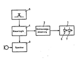
- the figure shows a block diagram which contains the most important function blocks for the control of a visual display in an answering machine according to the invention.
- control logic 4 is connected to an announcement text memory 3, a record button 5 and a display control 2 to which the display 1, consisting of the display elements 6 and 7, is connected.
- the user need only observe two display elements while speaking or listening to the announcement text and can thus concentrate fully on his text.
- he After pressing the record button 5, he first waits for the first display element 6 to light up. As soon as this has been done, he can start speaking the text.
- the display control 2 now keeps this display element in the ignited state until the minimum speaking time for the announcement text (message and notification text) has expired.
- the second display element 7 is ignited by means of the display control 2 and maintains this state until the end of the prescribed maximum speaking time.
- the user must therefore design his text length so that the second display element 7 lights up after the announcement has ended.
- the announcement text is too short in time when the first display element is still ignited, and too long in time if neither of the two display elements lights up.
- the control logic 4 stops the recording device at this point.
- the display control 2 switches continuously between the two display elements 6 and 7 during this time, so that they flash alternately. This indicates the waiting position of the answering machine for the final announcement (second part of the announcement). In this waiting position, however, he remains only for a limited period in which the final announcement must take place. If this does not happen, the answering machine, controlled by the control logic 4, returns to its starting position.
- the visual display control 2 receives a changeover command from the control logic 4, which causes the display elements 6 and 7 to be ignited in changed time phases.
- These time phases in which either the first display element 6 or the second display element 7 is activated and ignited correspond to the minimum and maximum speaking times for the final announcement.
- the display elements are advantageously designed as light-emitting diodes or liquid crystal displays.
- tape and / or solid-state memories can be used as the announcement text memory.
Landscapes
- Engineering & Computer Science (AREA)
- Signal Processing (AREA)
- Control Of Indicators Other Than Cathode Ray Tubes (AREA)
Claims (5)
Applications Claiming Priority (2)
| Application Number | Priority Date | Filing Date | Title |
|---|---|---|---|
| DE19833313306 DE3313306A1 (de) | 1983-04-13 | 1983-04-13 | Automatischer anrufbeantworter |
| DE3313306 | 1983-04-13 |
Publications (3)
| Publication Number | Publication Date |
|---|---|
| EP0122331A2 EP0122331A2 (fr) | 1984-10-24 |
| EP0122331A3 EP0122331A3 (en) | 1986-03-19 |
| EP0122331B1 true EP0122331B1 (fr) | 1988-12-14 |
Family
ID=6196237
Family Applications (1)
| Application Number | Title | Priority Date | Filing Date |
|---|---|---|---|
| EP83112330A Expired EP0122331B1 (fr) | 1983-04-13 | 1983-12-08 | Répondeur téléphonique automatique |
Country Status (2)
| Country | Link |
|---|---|
| EP (1) | EP0122331B1 (fr) |
| DE (2) | DE3313306A1 (fr) |
Family Cites Families (2)
| Publication number | Priority date | Publication date | Assignee | Title |
|---|---|---|---|---|
| BE509912A (fr) * | ||||
| GB719981A (en) * | 1952-09-23 | 1954-12-08 | John Garfield Fontaine | Improvements in and relating to automatic telephone answering and recording machines |
-
1983
- 1983-04-13 DE DE19833313306 patent/DE3313306A1/de not_active Withdrawn
- 1983-12-08 EP EP83112330A patent/EP0122331B1/fr not_active Expired
- 1983-12-08 DE DE8383112330T patent/DE3378718D1/de not_active Expired
Also Published As
| Publication number | Publication date |
|---|---|
| EP0122331A2 (fr) | 1984-10-24 |
| DE3313306A1 (de) | 1984-10-18 |
| EP0122331A3 (en) | 1986-03-19 |
| DE3378718D1 (en) | 1989-01-19 |
Similar Documents
| Publication | Publication Date | Title |
|---|---|---|
| EP0122331B1 (fr) | Répondeur téléphonique automatique | |
| DE2902211C3 (de) | Audiovisuelles Lerngerät | |
| DE2335959A1 (de) | Automatische telefon-ueberwachungsanlage | |
| DE4134551A1 (de) | Spielergebnis-berechnungsvorrichtung | |
| DE3325810C2 (de) | Video-Einrichtung | |
| DE3740472A1 (de) | Uhr | |
| DE451134C (de) | Maschine zum Sortieren von Lochkarten nach Lochkombinationen | |
| DE1296405B (de) | Vorrichtung zur Steuerung des Abspielvorgangs einer Anzahl von Schallplatten | |
| DE1116740B (de) | Selbsttaetiger Nummernwahlimpulsgeber fuer Teilnehmerstellen in Fernmelde-, insbesondere Fernsprechanlagen | |
| DE1302825C2 (de) | Verfahren zum aufzeichnen einer in sich geschlossenen, stossfreien uhrtaktfolge auf rotierende magnetschichtspeicher, z.b. magnettrommeln | |
| DE8800450U1 (de) | Vorrichtung zur Bereithaltung und Kontrolle von Billardkugeln | |
| DE2728708C2 (de) | Wiedergabesteuerungen für Diktiergeräte | |
| DE1930571A1 (de) | Automatische Kontrolle der Redezeit | |
| DD265967A1 (de) | Digitaler zeilenwahlschalter | |
| DE278498C (fr) | ||
| DE2410104A1 (de) | Sprechender zeitnehmer | |
| DE1566934B2 (de) | Vorrichtung auf schiffen zur akustischen schiffs signal abgabe | |
| AT82362B (de) | Schaltvorrichtung zur Aufspeicherung von Stromimpulsen für selbsttätige Telephonschaltsysteme. | |
| DE595844C (de) | Schaltungsanordnung fuer elektromagnetische Schrittschaltwerke, die an gemeinsamer Leitung liegen, insbesondere fuer Fernsprechanlagen | |
| DE467621C (de) | Vorrichtung zum Einsetzen von Kontaktstiften in eine von einem Uhrwerk angetriebene Schalttrommel eines elektrischen Signalapparats | |
| DE274051C (fr) | ||
| DE2744525C2 (de) | Zeitgeber | |
| DE2738092A1 (de) | Einrichtung zum steuern von rollbandgeraeten | |
| DE1934567C3 (de) | Antriebsanordnung mit einem Elektromotor für ein Röntgenschichtaufnahmegerät | |
| CH644525A5 (en) | Apparatus for evaluating the result of a shot on a bowling alley |
Legal Events
| Date | Code | Title | Description |
|---|---|---|---|
| PUAI | Public reference made under article 153(3) epc to a published international application that has entered the european phase |
Free format text: ORIGINAL CODE: 0009012 |
|
| AK | Designated contracting states |
Designated state(s): DE FR GB IT |
|
| RAP1 | Party data changed (applicant data changed or rights of an application transferred) |
Owner name: GRUNDIG E.M.V. ELEKTRO-MECHANISCHE VERSUCHSANSTALT |
|
| RAP1 | Party data changed (applicant data changed or rights of an application transferred) |
Owner name: GRUNDIG E.M.V. ELEKTRO-MECHANISCHE VERSUCHSANSTALT |
|
| RAP1 | Party data changed (applicant data changed or rights of an application transferred) |
Owner name: GRUNDIG E.M.V. ELEKTRO-MECHANISCHE VERSUCHSANSTALT |
|
| PUAL | Search report despatched |
Free format text: ORIGINAL CODE: 0009013 |
|
| RHK1 | Main classification (correction) |
Ipc: H04M 1/65 |
|
| AK | Designated contracting states |
Kind code of ref document: A3 Designated state(s): DE FR GB IT |
|
| 17P | Request for examination filed |
Effective date: 19860409 |
|
| 17Q | First examination report despatched |
Effective date: 19870521 |
|
| GRAA | (expected) grant |
Free format text: ORIGINAL CODE: 0009210 |
|
| AK | Designated contracting states |
Kind code of ref document: B1 Designated state(s): DE FR GB IT |
|
| GBT | Gb: translation of ep patent filed (gb section 77(6)(a)/1977) | ||
| REF | Corresponds to: |
Ref document number: 3378718 Country of ref document: DE Date of ref document: 19890119 |
|
| ET | Fr: translation filed | ||
| ITF | It: translation for a ep patent filed | ||
| PLBE | No opposition filed within time limit |
Free format text: ORIGINAL CODE: 0009261 |
|
| STAA | Information on the status of an ep patent application or granted ep patent |
Free format text: STATUS: NO OPPOSITION FILED WITHIN TIME LIMIT |
|
| 26N | No opposition filed | ||
| PGFP | Annual fee paid to national office [announced via postgrant information from national office to epo] |
Ref country code: GB Payment date: 19891130 Year of fee payment: 7 |
|
| PGFP | Annual fee paid to national office [announced via postgrant information from national office to epo] |
Ref country code: FR Payment date: 19891227 Year of fee payment: 7 |
|
| ITTA | It: last paid annual fee | ||
| PGFP | Annual fee paid to national office [announced via postgrant information from national office to epo] |
Ref country code: DE Payment date: 19900113 Year of fee payment: 7 |
|
| PG25 | Lapsed in a contracting state [announced via postgrant information from national office to epo] |
Ref country code: GB Effective date: 19901208 |
|
| GBPC | Gb: european patent ceased through non-payment of renewal fee | ||
| PG25 | Lapsed in a contracting state [announced via postgrant information from national office to epo] |
Ref country code: FR Effective date: 19910830 |
|
| PG25 | Lapsed in a contracting state [announced via postgrant information from national office to epo] |
Ref country code: DE Effective date: 19910903 |
|
| REG | Reference to a national code |
Ref country code: FR Ref legal event code: ST |