EP0121713B1 - Türanordnung für das Bedienungsfeld eines Gerätes - Google Patents
Türanordnung für das Bedienungsfeld eines Gerätes Download PDFInfo
- Publication number
- EP0121713B1 EP0121713B1 EP84101956A EP84101956A EP0121713B1 EP 0121713 B1 EP0121713 B1 EP 0121713B1 EP 84101956 A EP84101956 A EP 84101956A EP 84101956 A EP84101956 A EP 84101956A EP 0121713 B1 EP0121713 B1 EP 0121713B1
- Authority
- EP
- European Patent Office
- Prior art keywords
- door
- door leaf
- strip
- contact strip
- closing edge
- Prior art date
- Legal status (The legal status is an assumption and is not a legal conclusion. Google has not performed a legal analysis and makes no representation as to the accuracy of the status listed.)
- Expired
Links
Images

Classifications
-
- G—PHYSICS
- G07—CHECKING-DEVICES
- G07F—COIN-FREED OR LIKE APPARATUS
- G07F19/00—Complete banking systems; Coded card-freed arrangements adapted for dispensing or receiving monies or the like and posting such transactions to existing accounts, e.g. automatic teller machines
- G07F19/20—Automatic teller machines [ATMs]
- G07F19/201—Accessories of ATMs
-
- G—PHYSICS
- G07—CHECKING-DEVICES
- G07F—COIN-FREED OR LIKE APPARATUS
- G07F19/00—Complete banking systems; Coded card-freed arrangements adapted for dispensing or receiving monies or the like and posting such transactions to existing accounts, e.g. automatic teller machines
- G07F19/20—Automatic teller machines [ATMs]
- G07F19/205—Housing aspects of ATMs
Definitions
- the invention relates to a door arrangement for the control panel of a device, in particular a cash dispenser, comprising a door leaf which can be displaced in its plane by means of a door drive between an open position releasing the control panel and a closed position covering the control panel, in which it is oriented in a direction transverse to the direction of displacement Closing edge at least approximately abuts a stop surface, and a touch device arranged on the door leaf and controlling the door drive with a touch strip which extends over the entire length of the closing edge and which acts against a force between a first position projecting beyond the closing edge and one with the closing edge aligned second position is adjustable.
- the invention applies in general to any type of device in which certain parts are to be secured against access by unauthorized persons or against external influences such as weather conditions.
- the invention is concerned with so-called automated teller machines, which are usually built into the outer wall of a building and are used in particular to dispense money outside of a bank's counter hours.
- automated teller machines which are usually built into the outer wall of a building and are used in particular to dispense money outside of a bank's counter hours.
- the outer door covering the control panel of the automated teller machine is opened after a customer card has been inserted into an interrogation device.
- the door arrangement should be relatively stable and have a correspondingly powerful door drive which cannot be stopped easily.
- a touch bar is adjustably mounted in the door leaf, which extends beyond its closing edge when the gate is open and is pressed into the door leaf when it encounters an obstacle, actuating a switch controlling the door drive.
- This door also has the disadvantage described above that the key bar is not actuated when the obstacle only protrudes into the closing gap by a distance corresponding to the thickness of the outer walls of the door.
- the door leaf would have to be very thick in the case of a solid construction, as is required for automated teller machines.
- the invention has for its object to provide a door arrangement of the type mentioned, in which the jamming of objects between the door leaf and the stop surface is reliably prevented over the entire length of the closing edge and which is robust and simple in design.
- This object is erfindun g convention under solved in that the taskbar is so guided on the door leaf inner side at an acute angle to the door leaf plane, that it touches in its first position the plane of the door leaf outer surface or cuts.
- each object initially comes into contact with the touch bar.
- the pushbutton bar is first shifted until its edge surface facing the stop surface is flush with the closing edge of the door leaf. A corresponding contact can then be actuated within this displacement path of the push-button bar, which stops the door drive.
- the push-button strip is thus pushed completely in front of the closing edge of the door leaf, so that the push-button device responds even if an object only projects into the gap between the door leaf and the stop surface by a distance corresponding to the thickness of the door leaf.
- the key strip is preferably guided in a guide strip which extends over the entire length of the closing edge and is fastened to the door leaf and has a guide groove for receiving the key strip.
- the touch bar is preferably biased into its first position, in which it extends beyond the closing edge of the door leaf. This is also of advantage in the door arrangements where the closing edge of the door leaf is formed by the lower edge thereof and in which the touch bar could thus fall down due to gravity when the door is opened.
- the pretensioning of the key strip in its first position overcomes any frictional resistance that could occur due to dirt in the guide of the key strip.
- the door drive is preferably controlled in such a way that at least one limit switch is arranged on the guide bar, which is connected to a control circuit for the door drive and whose switching element projects into the sliding path of the button bar.
- the guide bar and the touch bar are preferably arranged relative to the door leaf in such a way that the guide bar and the door leaf do not just touch the stop surface in the closed position thereof, in order to avoid scratching the stop surface when the door leaf and the guide rail are frequently put on.
- the key strip on its edge surface facing the stop surface can have at least one nose which rises slightly above this edge surface, a narrow nose preferably being provided at each end of the key strip.
- the touch bar also only touches the narrow surface with the narrow lugs so that it is not scratched.
- Fig. 1 denotes a wall in which a cash dispenser 12 which is known per se and can no longer be described is installed.
- This includes a control panel 14, of which in the present case only a keyboard 16 and a cash dispensing slot 18 are shown, for example.
- the control panel 14 can be covered by a sliding door arrangement 20, which is shown in its open state in FIG. 1, in which the door leaf is pushed into the automatic teller machine.
- the door 20 is generally opened by a customer inserting a customer card 22 through a slot 24 into an interrogation device. The arrangement described so far is known per se.
- the door 20 accordingly comprises a door leaf 26 which is formed, for example, from a steel sheet several millimeters thick.
- a guide bar 32 extending over the entire length of the closing edge 30, the lower edge surface 34 of which is flush with the closing edge 30 of the door leaf 26.
- the screws 28 pass through the guide bar in bores 36.
- a groove 38 extending over its entire length is formed for receiving a key bar 40, which also extends over the entire length of the closing edge 30 of the door leaf 26.
- the touch bar 40 is guided in the groove 38 in the direction of the double arrow A to move back and forth.
- the groove 38 and thus also the plane of movement of the key strip 40 form an acute angle a with the plane of the door leaf 26, so that the key strip 40 is therefore not displaceable parallel to the door leaf 26 but at an angle ⁇ relative to the door leaf 26.
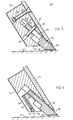
- the result of this is that when the door 20 is open, the key strip 40 slides under the closing edge 30 and intersects the plane corresponding to the outside of the door leaf 26, as is shown in FIGS. 3 to 5.
- the touch bar 40 is held in the groove 38 of the guide bar 32 by cylindrical pins 44 which are seated in cylindrical bores 46 in the guide bar 32 and each pass through an elongated hole 48 in the touch bar 40.
- the position and the length of the elongated holes 48 determine the displacement of the touch bar 40.
- the touch bar 40 is moved into its lower position, that is to say into its touch position, by a tension spring 50.
- the tension spring 50 is hooked on the one hand to a cylindrical pin 54 inserted in an elongated hole 52 of the guide bar 32 and engages with its other end on a bracket 56 which is connected to the touch or contact bar 40.
- the tension spring 50 and the bracket 56 are arranged in a groove 58 which is formed in the guide bar 32.
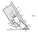
- FIG. 5 shows the connection between the key strip 40 and a control circuit, not shown, for the door drive, also not shown, for adjusting the door leaf 26.
- a microswitch 60 is provided, which is arranged in a recess 62 in the guide bar 32 (see also FIG. 2).
- the screws 64 which fix the microswitch 60 on the guide bar 32 extend through an elongated hole 66 formed in the guide bar 32, so that the microswitch can be adjusted in the direction of the double arrow B and thus adjusted.
- a switching plunger or switching element 68 which is actuated by the upper edge 70 of a window 72 formed in the key bar 40 when the key bar 40 is in its lower position or key position as shown in FIG. 5.
- solder connection 74 for connection to the control circuit of the door drive, not shown.
- the microswitch 60 is adjusted in such a way that the door drive is stopped when the push bar 40 is fully inserted into the groove 38 and its surface 76 facing the stop surface 42 is flush with the closing edge 30 of the door leaf 26 and the surface 34 of the guide rail 32 .
- two ribs 78 are formed on the underside 76 on the underside of the outer ends thereof, which ribs 78 raise about 0.4 mm above surface 76 and have a width of about 3 mm. The entire door arrangement thus lies only on the stop surface 42 with the ribs 78.
Landscapes
- Business, Economics & Management (AREA)
- Accounting & Taxation (AREA)
- Finance (AREA)
- Physics & Mathematics (AREA)
- General Physics & Mathematics (AREA)
- Power-Operated Mechanisms For Wings (AREA)
- Automobile Manufacture Line, Endless Track Vehicle, Trailer (AREA)
Description
- Die Erfindung betrifft eine Türanordnung für das Bedienungsfeld eines Gerätes, insbesondere eines Geldausgabegerätes, umfassend ein Türblatt, das mittels eines Türantriebes in seiner Ebene zwischen einer das Bedienungsfeld freigebenden Offenstellung und einer das Bedienungsfeld abdeckenden Schliessstellung verschiebbar ist, in der es mit einer quer zur Verschieberichtung gerichteten Schliesskante an einer Anschlagfläche mindestens annähernd anliegt, und eine an dem Türblatt angeordnete, den Türantrieb steuernde Tastvorrichtung mit einer Tastleiste, die sich über die gesamte Länge der Schliesskante erstreckt und die gegen eine Kraft zwischen einer über die Schliesskante hinausragenden ersten Stellung und einer mit der Schliesskante fluchtenden zweiten Stellung verstellbar ist.
- Die Erfindung gilt ganz allgemein für jede Art von Geräte, bei dem gewisse Teile gegen den Zugriff Unbefugter oder gegen äussere Einflüsse wie beispielsweise Witterungseinflüsse gesichert werden sollen. Insbesondere befasst sich jedoch die Erfindung mit sogenannten Bankautomaten, die in der Regel in die Aussenwand eines Gebäudes eingebaut sind und insbesondere zur Ausgabe von Geld ausserhalb der Schalterstunden eines Kreditinstitutes dienen. Üblicherweise wird die das Bedienungsfeld des Geldausgabeautomaten abdeckende Aussentür nach dem Einführen einer Kundenkarte in eine Abfragevorrichtung geöffnet. Um den Geldausgabeautomaten gegen Manipulation Unbefugter zu sichern, sollte die Türanordnung relativ stabil sein und einen entsprechend kräftigen Türantrieb besitzen, der sich nicht ohne weiteres anhalten lässt.
- Bei derartigen Türanordnungen besteht nun die Gefahr, dass beim Schliessen des Türblattes Gegenstände wie Kugelschreiber oder aber auch die Finger eines Benutzers zwischen der Schliesskante des Türblattes und der Anschlagfläche eingeklemmt werden. Es wurde bereits vorgeschlagen, den Schliessbereich der Türanordnung durch eine Lichtschranke zu überwachen. Bei aussen angeordneten Geräten wie den genannten Bankautomaten oder Geldausgabeautomaten besteht jedoch die Gefahr, dass die optischen Bauteile der Lichtschranke verschmutzen oder die Lichtschranke auf andere Weise bleibend blokkiert wird und damit den Schliessmechanismus behindert. Ferner ist bereits eine Türanordnung bekannt, bei der an der Innenseite des Türblattes eine um eine zur Schliesskante parallele Achse schwenkbare Leiste angeordnet ist, die bei geöffnetem Türblatt über die Schliesskanten hinaus nach unten hängt und beim Aufsetzen des Türblattes auf die Anschlagfläche verschwenkt wird. Diese Lösung hat den Nachteil, dass von der Tastvorrichtung Gegenstände nicht erfasst werden, die nur um eine der Dicke des Türblattes entsprechende Strecke in den Spalt zwischen Schliesskante und Anschlagfläche hineinragen: Den gleichen Nachteil besitzt auch eine aus der GB-A-2 069 039 bekannte Türanordnung, bei der an Innenseite des Türblattes eine nicht näher beschriebene Tastleiste angeordnet ist, die mit einer Steuervorrichtung zur Steuerung des Türantriebes verbunden ist. Schliesslich ist aus der US-A-3 315 766 ein horizontal verschiebbares Schiebetor für Fahrstühle und dergleichen bekannt, das jedoch die eingangs beschriebenen Merkmale aufweist.
- Bei diesem Schiebetor ist in dem Türblatt eine Tastleiste verstellbar gelagert, die bei geöffnetem Tor über dessen Schliessrand hinausragt und beim Auftreffen auf ein Hindernis in das Türblatt hineingedrückt wird, wobei sie einen den Türantrieb steuernden Schalter betätigt. Auch dieses Tor weist den oben beschriebenen Nachteil auf, dass die Tastleiste nicht betätigt wird, wenn das Hindernis nur um eine der Dicke der Toraussenwände entsprechende Strecke in den Schliessspalt hineinragt. Zudem müsste das Türblatt bei einer soliden Ausführung, wie sie für Bankautomaten benötigt wird, sehr dick sein.
- Der Erfindung liegt die Aufgabe zugrunde, eine Türanordnung der eingangs genannten Art anzugeben, bei der auf der gesamten Länge der Schliesskante das Einklemmen von Gegenständen zwischen dem Türblatt und der Anschlagfläche zuverlässig verhindert wird und die dabei robust und einfach in der Ausführung ist.
- Diese Aufgabe wird erfindungsgemäss dadurch gelöst, dass die Tastleiste an der Türblattinnenseite unter einem spitzen Winkel zur Türblattebene derart verschiebbar geführt ist, dass sie in ihrer ersten Stellung die Ebene der Türblattaussenfläche berührt oder schneidet.
- Bei der erfindungsgemässen Anordnung kommt jeder Gegenstand unabhängig davon, wie weit er in den Schliessweg des Türblattes hineinragt, zunächst mit der Tastleiste in Berührung. Beim weiteren Verschieben des Türblattes zusammen mit der Tastvorrichtung wird dann zunächst die Tastleiste verschoben, bis ihre der Anschlagfläche zugewandte Kantfläche mit der Schliesskante des Türblattes fluchtet. Innerhalb dieses Verschiebeweges der Tastleiste kann dann ein entsprechender Kontakt betätigt werden, der den Türantrieb stillsetzt. In der Offenstellung des Türblattes schiebt sich also die Tastleiste vollständig vor die Schliesskante des Türblattes, so dass die Tastvorrichtung auch dann anspricht, wenn ein Gegenstand nur um eine der Dicke des Türblattes entsprechende Strecke in den Spalt zwischen dem Türblatt und der Anschlagfläche hineinragt.
- Vorzugsweise ist die Tastleiste in einer sich über die gesamte Länge der Schliesskante erstrekkenden, an dem Türblatt befestigten Führungsleiste geführt, die eine Führungsnut zur Aufnahme der Tastleiste aufweist. Durch diese Führung der Tastleiste auf ihrer ganzen Länge ist ein Verbiegen oder Verkanten der Tastleiste praktisch ausgeschlossen, so dass die Tastvorrichtung robust und wenig störanflällig ist. Vorzugsweise ist die Tastleiste in ihre erste Stellung vorgespannt, in der sie sich über die Schliesskante des Türblattes hinaus erstreckt. Dies ist auch in den Türanordnungen von Vorteil, bei denen die Schliesskante des Türblattes von der Unterkante desselben gebildet wird und bei denen die Tastleiste somit beim Öffnen der Tür aufgrund der Schwerkraft nach unten fallen könnte. Die Vorspannung der Tastleiste in ihre erste Stellung überwindet gegebenenfalls Reibungswiderstände, die aufgrund von Schmutz in der Führung der Tastleiste auftreten könnten.
- Die Steuerung des Türantriebes erfolgt vorzugsweise so, dass an der Führungsleiste mindestens ein Endschalter angeordnet ist, der mit einer Steuerschaltung für den Türantrieb verbunden ist und dessen Schaltelement in den Schiebeweg der Tastleiste ragt. Dabei sind die Führungsleiste und die Tastleiste relativ zum Türblatt vorzugsweise so angeordnet, dass die Führungsleiste und das Türblatt in der Schliessstellung desselben die Anschlagfläche gerade nicht berühren, um ein Verkratzen der Anschlagfläche beim häufigen Aufsetzen des Türblattes und der Führungsleiste zu vermeiden. Aus dem gleichen Grunde kann auch die Tastleiste an ihrer der Anschlagfläche zugekehrten Kantfläche mindestens eine sich gerinfügig über diese Kantfläche erhebende Nase aufweisen, wobei vorzugsweise an jedem Ende der Tastleiste eine schmale Nase vorgesehen ist. Auch die Tastleiste setzt somit nur mit den schmalen Nasen auf der Anschlagfläche auf, so dass diese nicht verkratzt wird.
- Weitere Merkmale und Vorteile der Erfindung ergeben sich aus der folgenden Beschreibung, welche in Verbindung mit den beigefügten Zeichnungen die Erfindung anhand eines Ausführungsbeispiels erläutert. Es zeigen:
- Fig. 1 eine perspektivische schematische Darstellung eines durch die erfindungsgemässe Türanordnung verschliessbaren Gerätes,
- Fig. 2 eine Draufsicht auf die jeweils dem Türblatt zugekehrten Flächen der Führungsleiste und der Tastleiste,
- Fig. 3 einen Schnitt längs Linie 111-111 in Fig. 2,
- Fig. 4 einen Schnitt längs Linie IV-IV in Fig. 2 und
- Fig. 5 einen Schnitt längs Linie V-V in Fig. 2, jeweils in vergrössertem Massstab.
- In Fig. 1 ist mit 10 eine Wand bezeichnet, in der ein an sich bekannter und hier nicht mehr zu beschreibender Geldausgabeautomat 12 eingebaut ist. Dieser umfasst ein Bedienungsfeld 14, von dem im vorliegenden Falle nur eine Tastatur 16 und ein Geldausgabeschlitz 18 beispielsweise dargestellt sind. Das Bedienungsfeld 14 ist durch eine Schiebetüranordnung 20 abdeckbar, die in der Fig. 1 in ihrem geöffneten Zustand dargestellt ist, bei dem das Türblatt in den Geldausgabeautomaten hineingeschoben ist. Die Tür 20 wird in der Regel dadurch geöffnet, dass ein Kunde eine Kundenkarte 22 durch einen Schlitz 24 in eine Abfrageeinrichtung einschiebt. Die soweit beschriebene Anordnung ist an sich bekannt.
- Die Fig. 3 bis 5 zeigen den unteren, das heisst den der Schliesskante der Tür 20 nahen Bereich der Tür 20 in einem senkrecht zur Schliesskante verlaufenden Schnitt. Die Tür 20 umfasst demnach ein Türblatt 26, das beispielsweise von einem mehrere Millimeter starken Stahlblech gebildet ist. An der Innenseite des Türblattes 26 ist mit Hilfe von Schrauben 28 eine sich über die gesamte Länge der Schliesskante 30 erstreckende Führungsleiste 32 befestigt, deren untere Kantfläche 34 mit der Schliesskante 30 des Türblattes 26 fluchtet. Die Schrauben 28 durchsetzen dabei die Führungsleiste in Bohrungen 36.
- In der Führungsleiste 32 ist eine sich über deren gesamte Länge erstreckende Nut 38 zur Aufnahme einer sich ebenfalls über die gesamte Länge der Schliesskante 30 des Türblattes 26 erstreckenden Tastleiste 40 ausgebildet. Die Tastleiste 40 ist in der Nut 38 in Richtung des Doppelpfeiles A hin und her verschiebbar geführt. Die Nut 38 und damit auch die Bewegungsebene der Tastleiste 40 bilden mit der Ebene des Türblattes 26 einen spitzen Winkel a, so dass die Tastleiste 40 also nicht parallel zum Türblatt 26 sondern unter dem Winkel a gegenüber dem Türblatt 26 verschiebbar ist. Das hat zur Folge, dass sich die Tastleiste 40 bei geöffneter Tür 20 unter die Schliesskante 30 schiebt und die der Aussenseite des Türblattes 26 entsprechende Ebene schneidet, so wie dies in den Fig. 3 bis 5 dargestellt ist. Es ist somit unmöglich, dass ein Gegenstand in den Schliessbereich zwischen der Tür 20 und einer mit ihr zusammenwirkenden Anschlagfläche 42 von aussen hineinragt, der beim Schliessen der Tür 20 nicht zuerst von der Tastleiste 40 berührt wird. Damit wird verhindert, dass irgendein Gegenstand zwischen der Schliesskante 30 des Türblattes 26 und der Anschlagfläche 42 eingeklemmt wird, ohne dass er von der Tastvorrichtung erfasst würde.
- Gemäss den Fig. 2 und 3 wird die Tastleiste 40 in der Nut 38 der Führungsleiste 32 durch zylindrische Stifte 44 gehalten, die in zylindrischen Bohrungen 46 in der Führungsleiste 32 sitzen und jeweils ein Langloch 48 in der Tastleiste 40 durchsetzen. Die Lage und die Länge der Langlöcher 48 bestimmt den Verschiebeweg der Tastleiste 40.
- Gemäss den Fig. 2 und 4 wird die Tastleiste 40 durch eine Zugfeder 50 in ihre untere Lage, das heisst in ihre Taststellung verschoben. Die Zugfeder 50 ist einerseits an einem in einem Langloch 52 der Führungsleiste 32 eingesetzten Zylinderstift 54 eingehängt und greift mit ihrem anderen Ende an einem Bügel 56 an, der mit der Tast-oder Kontaktleiste 40 verbunden ist. Die Zugfeder 50 und der Bügel 56 sind dabei in einer Nut 58 angeordnet, die in der Führungsleiste 32 ausgebildet ist.
- In Fig. 5 ist die Verbindung zwischen der Tastleiste 40 und einem nicht dargestellten Steuerkreis für den ebenfalls nicht dargestellten Türantrieb zur Verstellung des Türblattes 26 dargestellt. Hierzu ist ein Mikroschalter 60 vorgesehen, der in einer Aussparung 62 in der Führungsleiste 32 angeordnet ist (siehe auch Fig. 2). Die den Mikroschalter 60 an der Führungsleiste 32 festlegenden Schrauben 64 greifen durch ein in der Führungsleiste 32 ausgebildetes Langloch 66, so dass der Mikroschalter in Richtung des Doppelpfeiles B verstellt und damit justiert werden kann. Am oberen Ende des Mikroschalters 60 befindet sich ein Schaltstössel oder Schaltelement 68, das durch den oberen Rand 70 eines in der Tastleiste 40 ausgebildeten Fensters 72 betätigt wird, wenn sich entsprechend der Darstellung in Fig. 5 die Tastleiste 40 in ihrer unteren Stellung oder Taststellung befindet. Am unteren Ende des Mikroschalters 60 befindet sich ein Lötanschluss 74 für die Verbindung mit der nicht dargestellten Steuerschaltung des Türantriebes.
- Der Mikroschalter 60 ist in der Weise justiert, dass der Türantrieb still gesetzt wird, wenn die Tastleiste 40 vollständig in die Nut 38 eingefahren ist und ihre der Anschlagfläche 42 zugewandte Fläche 76 mit der Schliesskante 30 des Türblattes 26 und der Fläche 34 der Führungsleiste 32 fluchtet. Um zu verhindern, dass in diesem Zustand das Türblatt 26 und die Führungsleiste 32 auf der Anschlagfläche 42 aufliegen und diese bei häufigem Öffnen und Schliessen der Türe verkratzen, sind an den äusseren Enden der Tastleiste 40 an deren Unterseite 76 zwei Rippen 78 ausgebildet, die sich etwa 0,4 mm über die Fläche 76 erheben und eine Breite von ca. 3 mm aufweisen. Damit liegt die gesamte Türanordnung nur mit den Rippen 78 auf der Anschlagfläche 42 auf.
Claims (6)
Priority Applications (1)
| Application Number | Priority Date | Filing Date | Title |
|---|---|---|---|
| AT84101956T ATE29792T1 (de) | 1983-03-16 | 1984-02-24 | Tueranordnung fuer das bedienungsfeld eines geraetes. |
Applications Claiming Priority (2)
| Application Number | Priority Date | Filing Date | Title |
|---|---|---|---|
| DE3309462 | 1983-03-16 | ||
| DE3309462A DE3309462C2 (de) | 1983-03-16 | 1983-03-16 | Türanordnung für das Bedienungsfeld eines Gerätes |
Publications (3)
| Publication Number | Publication Date |
|---|---|
| EP0121713A2 EP0121713A2 (de) | 1984-10-17 |
| EP0121713A3 EP0121713A3 (en) | 1985-09-25 |
| EP0121713B1 true EP0121713B1 (de) | 1987-09-16 |
Family
ID=6193673
Family Applications (1)
| Application Number | Title | Priority Date | Filing Date |
|---|---|---|---|
| EP84101956A Expired EP0121713B1 (de) | 1983-03-16 | 1984-02-24 | Türanordnung für das Bedienungsfeld eines Gerätes |
Country Status (5)
| Country | Link |
|---|---|
| US (1) | US4557072A (de) |
| EP (1) | EP0121713B1 (de) |
| JP (1) | JPS59189492A (de) |
| AT (1) | ATE29792T1 (de) |
| DE (2) | DE3309462C2 (de) |
Families Citing this family (7)
| Publication number | Priority date | Publication date | Assignee | Title |
|---|---|---|---|---|
| DE3503106A1 (de) * | 1985-01-30 | 1986-07-31 | Hubert 8000 München Kurz | Antrieb, insbesondere fuer tore, tueren und fenster |
| KR100425867B1 (ko) * | 2001-12-29 | 2004-04-01 | 엘지엔시스(주) | 현금자동 인출기의 고객 수취장치 |
| ES2496593T3 (es) | 2006-10-16 | 2014-09-19 | Assa Abloy Hospitality, Inc. | Red inalámbrica centralizada para propiedades de gran tamaño con múltiples habitaciones |
| US8493081B2 (en) * | 2009-12-08 | 2013-07-23 | Magna Closures Inc. | Wide activation angle pinch sensor section and sensor hook-on attachment principle |
| US9234979B2 (en) | 2009-12-08 | 2016-01-12 | Magna Closures Inc. | Wide activation angle pinch sensor section |
| WO2014016705A2 (en) | 2012-07-27 | 2014-01-30 | Assa Abloy Ab | Setback controls based on out-of-room presence information |
| US10050948B2 (en) | 2012-07-27 | 2018-08-14 | Assa Abloy Ab | Presence-based credential updating |
Family Cites Families (10)
| Publication number | Priority date | Publication date | Assignee | Title |
|---|---|---|---|---|
| US2854116A (en) * | 1953-01-02 | 1958-09-30 | Mercury Internat Res Company | Vending machine |
| US3237933A (en) * | 1963-09-16 | 1966-03-01 | Diebold Inc | Banking service equipment door safety construction |
| US3315766A (en) * | 1965-11-12 | 1967-04-25 | Otis Elevator Co | Retractable safety edge for doors |
| US3651986A (en) * | 1970-07-29 | 1972-03-28 | Docutel Corp | Credit card automatic currency dispenser |
| JPS51139154A (en) * | 1975-05-27 | 1976-12-01 | Omron Tateisi Electronics Co | Door control apparatus |
| JPS5841437Y2 (ja) * | 1978-12-12 | 1983-09-19 | 渡辺プレス工業株式会社 | プレス機に於ける安定扉の均衡支持装置 |
| JPS6029151B2 (ja) * | 1979-07-11 | 1985-07-09 | 富士電機株式会社 | 乗車券自動精算機のシヤツタ装置 |
| GB2069039B (en) * | 1980-02-01 | 1983-10-05 | Chubb Electronics Ltd | Equipment including retractabel protective-screens |
| DE3031499C2 (de) * | 1980-08-21 | 1982-09-09 | Karl 7298 Loßburg Hehl | Schutzschirm an einer Arbeitsmaschine |
| JPS58192167A (ja) * | 1982-05-06 | 1983-11-09 | Toshiba Corp | 自動取引装置 |
-
1983
- 1983-03-16 DE DE3309462A patent/DE3309462C2/de not_active Expired
-
1984
- 1984-02-24 DE DE8484101956T patent/DE3466303D1/de not_active Expired
- 1984-02-24 AT AT84101956T patent/ATE29792T1/de active
- 1984-02-24 EP EP84101956A patent/EP0121713B1/de not_active Expired
- 1984-03-06 US US06/586,795 patent/US4557072A/en not_active Expired - Fee Related
- 1984-03-14 JP JP59047299A patent/JPS59189492A/ja active Granted
Also Published As
| Publication number | Publication date |
|---|---|
| EP0121713A3 (en) | 1985-09-25 |
| EP0121713A2 (de) | 1984-10-17 |
| JPH0247793B2 (de) | 1990-10-22 |
| DE3309462A1 (de) | 1984-09-27 |
| US4557072A (en) | 1985-12-10 |
| JPS59189492A (ja) | 1984-10-27 |
| DE3466303D1 (en) | 1987-10-22 |
| ATE29792T1 (de) | 1987-10-15 |
| DE3309462C2 (de) | 1985-03-07 |
Similar Documents
| Publication | Publication Date | Title |
|---|---|---|
| DE10253138B4 (de) | Türvorrichtung für ein Fahrzeug und Verfahren zum Steuern einer Bewegung einer Tür | |
| EP1688566B1 (de) | Schloss mit Schwenkauslöser | |
| EP3452681B1 (de) | Dichtungsvorrichtung für eine schiebetür | |
| EP0121713B1 (de) | Türanordnung für das Bedienungsfeld eines Gerätes | |
| EP0255598B1 (de) | Kassenlade | |
| EP1235034B1 (de) | Verriegelungseinrichtung für die Tür eines Haushaltsgerätes, insbesondere Haushaltsgargerätes | |
| DE102021101448A1 (de) | Automatikschiebetür mit Schließeinrichtung und Verfahren zum Verriegeln | |
| DE3520861A1 (de) | Rueckdruecksperre an treibstangenbeschlaegen, insbesondere schluesselbetaetigbaren treibstangenschloessern | |
| DE3914895C2 (de) | Schloß für eine Tür | |
| DE3806576C2 (de) | ||
| DE3122581C2 (de) | Vorrichtung zum Be- und Entladen von Röngtenfilmkassetten | |
| DE2851658C2 (de) | ||
| EP0662556A1 (de) | Schlossvorrichtung für eine Tür oder ein Fenster | |
| DE19816091A1 (de) | Sperrvorrichtung für Schubladen in Möbeln | |
| EP0555630B1 (de) | Münzprüfer | |
| DE2049892A1 (de) | Handgesteuerte Schneidvorrichtung, ins besondere fur buromaßige Zwecke und das da zugehörige Herstellungsverfahren bzw ihre tunktionsmaßige Verfahrensweise | |
| DE2726908C2 (de) | Mit Zeituhr ausgestattetes Münz-PfandschloB | |
| DE19906349C1 (de) | Mechanische Feststellvorrichtung für den Türflügel einer Tür | |
| EP0550514B1 (de) | Durch einen rechner steuerbares gerät | |
| EP1405973B1 (de) | Beschlagmechanik für ein Drehkippfenster oder eine Drehkipptüre | |
| DE19745180A1 (de) | Andrückvorrichtung zwischen einem Flügel und einem Blendrahmen einer Tür, eines Fensters oder dergleichen | |
| DE202021104663U1 (de) | Schalter für Alarmaktivierung | |
| DE102004060501B4 (de) | Vorrichtung zur Positionierung eines Teiles | |
| EP0898760B1 (de) | Einrichtung zum lesen einer wertkarte | |
| DE69910910T2 (de) | Türschloss mit einer Riegelblockierungsvorrichtung gegen Einbruch |
Legal Events
| Date | Code | Title | Description |
|---|---|---|---|
| PUAI | Public reference made under article 153(3) epc to a published international application that has entered the european phase |
Free format text: ORIGINAL CODE: 0009012 |
|
| AK | Designated contracting states |
Designated state(s): AT BE CH DE FR GB IT LI LU NL SE |
|
| PUAL | Search report despatched |
Free format text: ORIGINAL CODE: 0009013 |
|
| AK | Designated contracting states |
Designated state(s): AT BE CH DE FR GB IT LI LU NL SE |
|
| 17P | Request for examination filed |
Effective date: 19850806 |
|
| 17Q | First examination report despatched |
Effective date: 19860716 |
|
| GRAA | (expected) grant |
Free format text: ORIGINAL CODE: 0009210 |
|
| AK | Designated contracting states |
Kind code of ref document: B1 Designated state(s): AT BE CH DE FR GB IT LI LU NL SE |
|
| REF | Corresponds to: |
Ref document number: 29792 Country of ref document: AT Date of ref document: 19871015 Kind code of ref document: T |
|
| REF | Corresponds to: |
Ref document number: 3466303 Country of ref document: DE Date of ref document: 19871022 |
|
| ET | Fr: translation filed | ||
| ITF | It: translation for a ep patent filed |
Owner name: MODIANO & ASSOCIATI S.R.L. |
|
| PG25 | Lapsed in a contracting state [announced via postgrant information from national office to epo] |
Ref country code: LU Free format text: LAPSE BECAUSE OF NON-PAYMENT OF DUE FEES Effective date: 19880229 |
|
| PLBE | No opposition filed within time limit |
Free format text: ORIGINAL CODE: 0009261 |
|
| STAA | Information on the status of an ep patent application or granted ep patent |
Free format text: STATUS: NO OPPOSITION FILED WITHIN TIME LIMIT |
|
| 26N | No opposition filed | ||
| PGFP | Annual fee paid to national office [announced via postgrant information from national office to epo] |
Ref country code: BE Payment date: 19890228 Year of fee payment: 6 |
|
| PG25 | Lapsed in a contracting state [announced via postgrant information from national office to epo] |
Ref country code: BE Effective date: 19900228 |
|
| BERE | Be: lapsed |
Owner name: NIXDORF COMPUTER A.G. Effective date: 19900228 |
|
| ITTA | It: last paid annual fee | ||
| PGFP | Annual fee paid to national office [announced via postgrant information from national office to epo] |
Ref country code: CH Payment date: 19910523 Year of fee payment: 8 |
|
| ITPR | It: changes in ownership of a european patent |
Owner name: CAMBIO RAGIONE SOCIALE;SIEMENS NIXDORF INFORMATION |
|
| NLT1 | Nl: modifications of names registered in virtue of documents presented to the patent office pursuant to art. 16 a, paragraph 1 |
Owner name: SIEMENS NIXDORF INFORMATIONSSYSTEME AKTIENGESELLSC |
|
| REG | Reference to a national code |
Ref country code: CH Ref legal event code: PFA Free format text: SIEMENS NIXDORF INFORMATIONSSYSTEME AKTIENGESELLSCHAFT |
|
| REG | Reference to a national code |
Ref country code: FR Ref legal event code: CD |
|
| PGFP | Annual fee paid to national office [announced via postgrant information from national office to epo] |
Ref country code: AT Payment date: 19920226 Year of fee payment: 9 |
|
| PGFP | Annual fee paid to national office [announced via postgrant information from national office to epo] |
Ref country code: GB Payment date: 19920228 Year of fee payment: 9 |
|
| PG25 | Lapsed in a contracting state [announced via postgrant information from national office to epo] |
Ref country code: LI Effective date: 19920229 Ref country code: CH Effective date: 19920229 |
|
| PGFP | Annual fee paid to national office [announced via postgrant information from national office to epo] |
Ref country code: NL Payment date: 19920229 Year of fee payment: 9 |
|
| REG | Reference to a national code |
Ref country code: CH Ref legal event code: PL |
|
| PGFP | Annual fee paid to national office [announced via postgrant information from national office to epo] |
Ref country code: SE Payment date: 19930218 Year of fee payment: 10 |
|
| PGFP | Annual fee paid to national office [announced via postgrant information from national office to epo] |
Ref country code: FR Payment date: 19930219 Year of fee payment: 10 |
|
| PG25 | Lapsed in a contracting state [announced via postgrant information from national office to epo] |
Ref country code: GB Effective date: 19930224 Ref country code: AT Effective date: 19930224 |
|
| PGFP | Annual fee paid to national office [announced via postgrant information from national office to epo] |
Ref country code: DE Payment date: 19930422 Year of fee payment: 10 |
|
| PG25 | Lapsed in a contracting state [announced via postgrant information from national office to epo] |
Ref country code: NL Effective date: 19930901 |
|
| NLV4 | Nl: lapsed or anulled due to non-payment of the annual fee | ||
| GBPC | Gb: european patent ceased through non-payment of renewal fee |
Effective date: 19930224 |
|
| PG25 | Lapsed in a contracting state [announced via postgrant information from national office to epo] |
Ref country code: SE Effective date: 19940225 |
|
| PG25 | Lapsed in a contracting state [announced via postgrant information from national office to epo] |
Ref country code: FR Effective date: 19941031 |
|
| PG25 | Lapsed in a contracting state [announced via postgrant information from national office to epo] |
Ref country code: DE Effective date: 19941101 |
|
| REG | Reference to a national code |
Ref country code: FR Ref legal event code: ST |
|
| EUG | Se: european patent has lapsed |
Ref document number: 84101956.5 Effective date: 19940910 |