EP0120292A2 - Elément de construction - Google Patents
Elément de construction Download PDFInfo
- Publication number
- EP0120292A2 EP0120292A2 EP84101844A EP84101844A EP0120292A2 EP 0120292 A2 EP0120292 A2 EP 0120292A2 EP 84101844 A EP84101844 A EP 84101844A EP 84101844 A EP84101844 A EP 84101844A EP 0120292 A2 EP0120292 A2 EP 0120292A2
- Authority
- EP
- European Patent Office
- Prior art keywords
- bars
- frame
- horizontal
- component according
- bar
- Prior art date
- Legal status (The legal status is an assumption and is not a legal conclusion. Google has not performed a legal analysis and makes no representation as to the accuracy of the status listed.)
- Withdrawn
Links
Images


Classifications
-
- E—FIXED CONSTRUCTIONS
- E04—BUILDING
- E04B—GENERAL BUILDING CONSTRUCTIONS; WALLS, e.g. PARTITIONS; ROOFS; FLOORS; CEILINGS; INSULATION OR OTHER PROTECTION OF BUILDINGS
- E04B1/00—Constructions in general; Structures which are not restricted either to walls, e.g. partitions, or floors or ceilings or roofs
- E04B1/348—Structures composed of units comprising at least considerable parts of two sides of a room, e.g. box-like or cell-like units closed or in skeleton form
- E04B1/34815—Elements not integrated in a skeleton
- E04B1/34838—Elements not integrated in a skeleton the supporting structure consisting of wood
Definitions
- the invention relates to a prefabricated component for the construction of buildings, in particular single-family houses, according to the prefabricated construction principle in grid construction.
- prefabricated buildings it is known to prefabricate more or less large plate-shaped components and to assemble them at the construction site. You go so far that you prefabricate entire walls with the appropriate installations and assemble them at the construction site.
- the invention has for its object to provide a component of the specified type which, despite appropriate standardization, can largely take account of the static conditions, without bringing about an excessive spatial limitation.
- the component should be particularly suitable for timber construction.
- the component designed according to the invention is a spatial element.
- This element which preferably has a cuboid shape, is formed by a skeleton of horizontal and vertical bars as well as an inclined support.
- the static conditions are taken into account by the arrangement of the two rigid rectangular frames and the diagonal support.
- the component described here is particularly suitable for wooden structures. If a building, for example a single-family house, is assembled from several components, the construction of the individual spatial skeletons (horizontal bars, vertical bars, nodes, connections) advantageously remains visible, which on the one hand helps to reduce costs and on the other hand further improves the aesthetic appearance of the construction .
- the component according to the invention offers a number of possible variations with regard to prefabrication.
- the rigid rectangular frames together with the horizontal bars and the inclined support are prefabricated in the factory, transported to the construction site and assembled there to form the spatial skeleton.
- the Rectangular frame created in wood glue construction.
- the horizontal bars and the diagonal support are screwed to the frame at the construction site.
- the component according to the invention is manufactured as a whole in the factory and transported to the construction site as a spatial structure. This eliminates the additional assembly effort at the construction site, but the transport may be more difficult.
- the component is already a finished room cell, i.e. with the required wall cladding, created in the factory and transported to the construction site. Since the planned walls in no way fulfill static tasks (no load-bearing walls), there are great possibilities for variation with regard to the arrangement and design of the walls.
- a crucial feature of the invention is the design of the rectangular frame.
- the vertical bars of a frame each consist of a corner bar and two side bars, which are assembled in the form of an angle.
- the horizontal bars of the frame are connected to the vertical bars in such a way that they rest on or engage under the side bar located in the frame plane behind the corner bar.
- On the other side bars lie the horizontal ceiling bars arranged perpendicular to the frame level.
- the horizontal bars arranged both in the frame plane and perpendicular to it are not arranged in the plane of the corner bar or the adjacent side bar, but rather rest on or engage under the side bar located in the bar plane behind the corner bar.
- the respective horizontal bars are arranged offset in relation to the respective corner bars into the interior of the component, so that a distance corresponding to the width of the corner bars remains between the outer edge of the corner bars and the outer edge of the horizontal bars.
- This special arrangement has the advantage that, when components are placed next to one another, the adjacent corner bars and side bars of the vertical bars butt against one another, but not the adjacent horizontal bars. There is therefore sufficient space between adjacent components for the arrangement of partition walls and - after attaching these partition walls - there is still enough space for the arrangement of installations (pipes, cables, etc.), which therefore do not have to be accommodated in the partition walls themselves.
- the corner bars of the vertical bars of the frame take on a further function.
- the corner bars represent an additional anti-tilt device for the horizontal bars.
- the three individual bars of the frame vertical bars preferably each have an approximately square cross cut open, while the horizontal bars of the component have a right cross section about twice the cross-sectional size of the vertical individual bars.
- the horizontal bars have a sufficient height in order to be able to accommodate horizontal bars, which extend perpendicularly to them and are provided with corresponding recesses, by means of recesses extending over half the height of the bars.
- the two middle bars are each supported by the horizontal bars of the frame.
- the component designed according to the invention has a cuboid shape.
- the two rigid rectangular frames are arranged on the short side when viewed in cross section.
- the height of the component is not critical and can be based on the usual storey heights (2.50 m).
- the component advantageously has a grid dimension (from the outer edge corner bar) of 2.25 mx 4.50 m.
- the horizontal bars for connecting the frames are provided in the center with longitudinal grooves for receiving ceiling and floor elements. Such elements can therefore be inserted between adjacent horizontal bars and are held in the corresponding grooves. It can be chipboard, for example, the remaining spaces being filled with insulating materials (mineral wool). Finally, a particle board layer can be used. Special examples for the construction of interior and External walls are described below.
- buildings can thus be created in a simple and inexpensive manner. No elaborate foundations are required for this, since the work is done with rigid spatial structures. Simple strip-like or punctiform foundations are sufficient. Extensive standardization can be achieved by working with such components. Essentially, only three different rod lengths are required for the component itself. Spatial limitations due to the existing grid dimension are essentially not given, since the individual walls of the component do not have to be fanned out due to the structural requirements, but can remain open. The required inclined support is negligible because it takes up only a small wall space and can be arranged where a continuous wall is to be arranged anyway. One inclined support is sufficient for each component.
- the components are designed as wooden structures. are.
- the individual bar elements are deliberately not clad so that the load-bearing structure remains visible. Due to the provided corner bars of the frame vertical bars, which are longer than the associated side bars, nodes can be formed particularly cheaply, since the corresponding node bars can rest on the corner bar. This also applies to rafters.
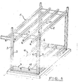
- FIG. 1 shows an exemplary embodiment of a component designed according to the invention.
- the device 1 presents a three-dimensional skeleton of a series of horizontal and vertical rods.
- the required Schrä g support is in this case not shown.
- the element comprises two rigid rectangular frames 2, each consisting of two vertical bars 3 and two horizontal bars 4, 9 connecting them together.
- the component is a wooden construction, the two rigid frames being made using the glue method.
- the vertical bars 3 of the rigid frame each consist of three individual bars, which are arranged at an angle and glued together. This is a corner bar 5 and two side bars 6, 7.
- the corner bar 5 is longer than the two side bars.
- the individual bars of the respective frame vertical bars have an approximately square cross section.
- the two horizontal bars 4, 9 of the frame have a rectangular cross section that is approximately twice as large as the cross section of the individual bars of the vertical bars. These horizontal bars are not arranged in the plane of the corner bars 5, but in the plane of the side bars 7 located behind the corner bars.
- the corresponding ceiling bars 4 rest on these side bars 7, while the floor bars 9 engage under the side bars.
- the corner bar 5 also acts as an anti-tilt device for the horizontal bars.
- the horizontal bars of the frame are thus offset from the corner bars. There is therefore a free space between the corner bars, which can be used for lining or creating walls.
- the same principle is implemented in the plane running perpendicular to the frame plane.
- the horizontal bars 8, 10 connecting the frames to each other are also not arranged in the plane of the corner bars themselves, but in the plane of the side bar 6 behind the corner bar.
- the ceiling bars 8 rest on the corresponding side bars 6, while the floor bars 10 Reach under the side bars or rest on the horizontal floor bars 9 of the frame.
- each side bar 5, 6 of the frame vertical bars carries a ceiling bar.
- a total of four ceiling bars 8 are provided which connect the frames to one another.
- four floor bars 10 are provided.
- the middle ceiling and floor bars rest on the corresponding horizontal bars of the frame, whereby At the respective crossing points, recesses 12 extending over half the height of the crossing bars are provided. The bars are therefore embedded in one another.
- all the ceiling and floor bars connecting the frames are provided approximately in the middle of their height with lateral longitudinal grooves 11, which serve to accommodate cladding elements (chipboard) for the ceiling and floor.
- the ceiling rods 8 connecting the frames to one another have a greater length than the distance between the frame planes.
- the above rod sections are used for the roof construction and could, for example, form a support for corresponding rafters (not shown), which can rest against the continuous corner bars. Furthermore, a gutter can be arranged on the outer ends of the projecting sections.
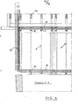
- Figures 2 to 4 show parts of a single family house, which is composed of several components 1, 20.
- Figure 3 shows a plan
- Figure 2 and Figure 4 show sections along lines A-A and B-B in Figure 3.
- the supporting bars i.e. the components of the components, highlighted.
- the horizontal frame bars 4, 9 can be seen in FIG. 2.
- the inclined support 13 provided in a wall plane of the component is shown.
- a rafter 14 is indicated, which bears against a corner bar 5 of a frame vertical bar.
- the building element 1 shown in FIG. 2 is one that has two Has outer walls 17, 22, a continuous inner wall 21 and a free side.
- two other elements 20, 30 are set.
- the vertical bars 3 of the respective elements abut one another.
- the elements can already be manufactured in the factory as finished room cells and are then only assembled together at the construction site or a corresponding outer wall covering is attached. If two elements are put together, their adjacent wall sections form a common inner wall 21, which in the illustrated embodiment has the following structure: 1 6 mm chipboard, 58 mm mineral wool, 32 mm air layer, 58 mm mineral wool and 16 mm chipboard, so that an inner wall thickness of results in a total of 180 mm.
- An outer wall 17, 22 has the following structure: 16 mm chipboard, 58 mm mineral wool, 16 mm chipboard, 50 mm hard foam, 45 mm air layer, 115 mm facing, so that there is a total outer wall thickness of 300 mm. It can be seen from this that the cladding of the component is constructed essentially uniformly, with a hard foam layer and a corresponding veneer only having to be subsequently applied to an external wall at the construction site.
- Figure 4 shows the arrangement of a bottom wall 16 and top wall 15. It can be seen that 8 and 10 chipboard are inserted into the longitudinal grooves 11 of the horizontal bars. There is a layer of mineral wool over these particle boards, followed by a second particle board layer applied to the rods 10, 8.
- the floor and ceiling walls can also be made in the factory.
Landscapes
- Engineering & Computer Science (AREA)
- Architecture (AREA)
- Physics & Mathematics (AREA)
- Electromagnetism (AREA)
- Civil Engineering (AREA)
- Structural Engineering (AREA)
- Conveying And Assembling Of Building Elements In Situ (AREA)
- Rod-Shaped Construction Members (AREA)
Applications Claiming Priority (2)
| Application Number | Priority Date | Filing Date | Title |
|---|---|---|---|
| DE19833306456 DE3306456A1 (de) | 1983-02-24 | 1983-02-24 | Bauelement |
| DE3306456 | 1983-02-24 |
Publications (2)
| Publication Number | Publication Date |
|---|---|
| EP0120292A2 true EP0120292A2 (fr) | 1984-10-03 |
| EP0120292A3 EP0120292A3 (fr) | 1986-07-16 |
Family
ID=6191718
Family Applications (1)
| Application Number | Title | Priority Date | Filing Date |
|---|---|---|---|
| EP84101844A Withdrawn EP0120292A3 (fr) | 1983-02-24 | 1984-02-22 | Elément de construction |
Country Status (2)
| Country | Link |
|---|---|
| EP (1) | EP0120292A3 (fr) |
| DE (1) | DE3306456A1 (fr) |
Cited By (3)
| Publication number | Priority date | Publication date | Assignee | Title |
|---|---|---|---|---|
| FR2598731A1 (fr) * | 1986-05-14 | 1987-11-20 | Daniel Lafon | Ossature de bois pour batiments, constituee de poutres sablieres jouant a la fois le role d'un chainage, de linteaux et de support des fermes, et de poteaux de support desdites poutres et des murs et fixes a un socle metallique. |
| EP0568165A1 (fr) * | 1992-04-02 | 1993-11-03 | Manfred Dipl.-Ing. Wahls | Méthode d'intégration pour construction et bloc de construction pour sa mise en oeuvre |
| EP0953697A2 (fr) * | 1998-03-31 | 1999-11-03 | A. Jandl Patentholding KEG | Maison |
Families Citing this family (3)
| Publication number | Priority date | Publication date | Assignee | Title |
|---|---|---|---|---|
| DE3938231A1 (de) * | 1989-11-17 | 1990-06-13 | Bernhard Backs | Dachbungalow |
| DE9319162U1 (de) * | 1993-11-25 | 1994-03-24 | Apart Mobil Mobilheimbau Und V | Transportable Wohneinheit |
| DE19512690A1 (de) * | 1995-04-07 | 1996-10-10 | Walter M Kroner | Verfahren zum Herstellen eines Fertigteilhauses |
Citations (3)
| Publication number | Priority date | Publication date | Assignee | Title |
|---|---|---|---|---|
| AT166104B (fr) * | ||||
| DE826347C (de) * | 1948-10-02 | 1951-12-27 | Krauth & Co | Zusammengesetztes profiliertes Holzbauglied |
| GB2104612A (en) * | 1981-03-16 | 1983-03-09 | Rainham Timber Engineering Co | Frame joints |
Family Cites Families (1)
| Publication number | Priority date | Publication date | Assignee | Title |
|---|---|---|---|---|
| DE2456620A1 (de) * | 1974-11-29 | 1976-08-12 | Iii Emile Joseph Lacoste | Ein- oder mehrstoeckiges gebaeude |
-
1983
- 1983-02-24 DE DE19833306456 patent/DE3306456A1/de not_active Ceased
-
1984
- 1984-02-22 EP EP84101844A patent/EP0120292A3/fr not_active Withdrawn
Patent Citations (3)
| Publication number | Priority date | Publication date | Assignee | Title |
|---|---|---|---|---|
| AT166104B (fr) * | ||||
| DE826347C (de) * | 1948-10-02 | 1951-12-27 | Krauth & Co | Zusammengesetztes profiliertes Holzbauglied |
| GB2104612A (en) * | 1981-03-16 | 1983-03-09 | Rainham Timber Engineering Co | Frame joints |
Non-Patent Citations (1)
| Title |
|---|
| MITTAG, 15. Auflage, 1971, Seite 132, INSTITUT F]R BAUPLANUNG UND BAUTECHNIK, Detmold; Abschnitt: Holzbalkendecken * |
Cited By (4)
| Publication number | Priority date | Publication date | Assignee | Title |
|---|---|---|---|---|
| FR2598731A1 (fr) * | 1986-05-14 | 1987-11-20 | Daniel Lafon | Ossature de bois pour batiments, constituee de poutres sablieres jouant a la fois le role d'un chainage, de linteaux et de support des fermes, et de poteaux de support desdites poutres et des murs et fixes a un socle metallique. |
| EP0568165A1 (fr) * | 1992-04-02 | 1993-11-03 | Manfred Dipl.-Ing. Wahls | Méthode d'intégration pour construction et bloc de construction pour sa mise en oeuvre |
| EP0953697A2 (fr) * | 1998-03-31 | 1999-11-03 | A. Jandl Patentholding KEG | Maison |
| EP0953697A3 (fr) * | 1998-03-31 | 1999-12-08 | A. Jandl Patentholding KEG | Maison |
Also Published As
| Publication number | Publication date |
|---|---|
| DE3306456A1 (de) | 1984-09-06 |
| EP0120292A3 (fr) | 1986-07-16 |
Similar Documents
| Publication | Publication Date | Title |
|---|---|---|
| DE3430612A1 (de) | Metall-raumfachwerk aus einzelelementen zum errichten von gebaeuden | |
| EP0813638B1 (fr) | Construction | |
| EP0120292A2 (fr) | Elément de construction | |
| DE3532846C2 (de) | Bauelement zur Erstellung von Gebäuden, auch zur Erstellung von Gebäudemodellen | |
| DE8008815U1 (de) | Stuetze zur erstellung von gebaeuden | |
| CH687884A5 (de) | Holzbautafel. | |
| DE19820438C1 (de) | Rahmenkörpersystem für in Fertigbauweise zu errichtende Gebäude | |
| DE19653340C1 (de) | Bausatz vorgefertigter Bauelemente für Wände und/oder Decken von Häusern | |
| DE102010018625A1 (de) | Wandelement und modulare Wand sowie Verfahren zur Nutzung von Sonnenenergie | |
| DE3203366A1 (de) | Modulares bausystem | |
| DE19916247A1 (de) | Baukastensystem für Fertighäuser | |
| EP0882849A2 (fr) | Elément de construction pour parois | |
| DE1912948A1 (de) | Bauplatte und aus dieser gefertigte Bauelemente | |
| DE829943C (de) | Wand aus duennen Platten | |
| DE4229719A1 (de) | Bauelementensatz für ein Gebäude | |
| DE3117182A1 (de) | Bausystem fuer insbesondere mehrgeschossige gebaeude | |
| DE102004060288B4 (de) | Gebäudemodul | |
| DE19745783A1 (de) | Holzsystemhaus | |
| AT405660B (de) | Gebäude | |
| DE1609361C3 (de) | Gebäude mit vorgefertigten, geschlossenen, einzelligen Rahmenelementen aus Stahlbeton | |
| DE2065437A1 (de) | Wohnbauwerk mit mehreren aneinander angrenzenden, aus vorgefertigten raumzellen bestehenden einzelwohnbauwerken | |
| DE19739402C2 (de) | Gebäudeecke für ein Haus in Holzbauweise | |
| DE19714792A1 (de) | Fertighaus und vorgefertigtes Element hierfür | |
| EP0128294A2 (fr) | Elément de mur | |
| AT328685B (de) | Aussenwandkonstruktion in grosstafelbauweise |
Legal Events
| Date | Code | Title | Description |
|---|---|---|---|
| PUAI | Public reference made under article 153(3) epc to a published international application that has entered the european phase |
Free format text: ORIGINAL CODE: 0009012 |
|
| AK | Designated contracting states |
Designated state(s): AT BE CH FR GB IT LI LU NL SE |
|
| PUAL | Search report despatched |
Free format text: ORIGINAL CODE: 0009013 |
|
| AK | Designated contracting states |
Kind code of ref document: A3 Designated state(s): AT BE CH FR GB IT LI LU NL SE |
|
| STAA | Information on the status of an ep patent application or granted ep patent |
Free format text: STATUS: THE APPLICATION IS DEEMED TO BE WITHDRAWN |
|
| 18D | Application deemed to be withdrawn |
Effective date: 19860828 |