EP0115692B1 - Mittel zur Befestigung an Wänden - Google Patents
Mittel zur Befestigung an Wänden Download PDFInfo
- Publication number
- EP0115692B1 EP0115692B1 EP83307882A EP83307882A EP0115692B1 EP 0115692 B1 EP0115692 B1 EP 0115692B1 EP 83307882 A EP83307882 A EP 83307882A EP 83307882 A EP83307882 A EP 83307882A EP 0115692 B1 EP0115692 B1 EP 0115692B1
- Authority
- EP
- European Patent Office
- Prior art keywords
- composition
- socket
- holding member
- fixing device
- adhesive
- Prior art date
- Legal status (The legal status is an assumption and is not a legal conclusion. Google has not performed a legal analysis and makes no representation as to the accuracy of the status listed.)
- Expired
Links
- 239000000203 mixture Substances 0.000 claims abstract description 106
- 239000000853 adhesive Substances 0.000 claims abstract description 55
- 230000001070 adhesive effect Effects 0.000 claims abstract description 55
- 239000008188 pellet Substances 0.000 claims abstract description 25
- 239000004033 plastic Substances 0.000 claims abstract description 25
- 229920003023 plastic Polymers 0.000 claims abstract description 25
- 239000004848 polyfunctional curative Substances 0.000 claims abstract description 23
- 239000003822 epoxy resin Substances 0.000 claims abstract description 6
- 229920000647 polyepoxide Polymers 0.000 claims abstract description 6
- 239000004952 Polyamide Substances 0.000 claims abstract description 4
- 229920002647 polyamide Polymers 0.000 claims abstract description 4
- 239000000463 material Substances 0.000 claims description 23
- 238000003825 pressing Methods 0.000 claims description 6
- 238000002156 mixing Methods 0.000 claims description 4
- 230000000717 retained effect Effects 0.000 claims description 4
- 239000000945 filler Substances 0.000 claims description 3
- 238000000034 method Methods 0.000 claims description 3
- 229910052751 metal Inorganic materials 0.000 abstract description 6
- 239000002184 metal Substances 0.000 abstract description 6
- LSDPWZHWYPCBBB-UHFFFAOYSA-N Methanethiol Chemical compound SC LSDPWZHWYPCBBB-UHFFFAOYSA-N 0.000 abstract description 5
- 150000001412 amines Chemical class 0.000 abstract description 5
- 239000011521 glass Substances 0.000 abstract description 4
- 239000011435 rock Substances 0.000 abstract description 3
- 239000002023 wood Substances 0.000 abstract description 2
- 241000196324 Embryophyta Species 0.000 description 18
- 210000003811 finger Anatomy 0.000 description 6
- -1 masonry Substances 0.000 description 6
- 230000001681 protective effect Effects 0.000 description 5
- 239000004567 concrete Substances 0.000 description 4
- 101100327917 Caenorhabditis elegans chup-1 gene Proteins 0.000 description 3
- 239000004677 Nylon Substances 0.000 description 3
- 239000004698 Polyethylene Substances 0.000 description 3
- 239000010410 layer Substances 0.000 description 3
- 229920001778 nylon Polymers 0.000 description 3
- 229920000573 polyethylene Polymers 0.000 description 3
- 239000004743 Polypropylene Substances 0.000 description 2
- 229910000831 Steel Inorganic materials 0.000 description 2
- 239000000654 additive Substances 0.000 description 2
- 239000004568 cement Substances 0.000 description 2
- 239000011248 coating agent Substances 0.000 description 2
- 238000000576 coating method Methods 0.000 description 2
- 238000004040 coloring Methods 0.000 description 2
- 229920006332 epoxy adhesive Polymers 0.000 description 2
- 229920001155 polypropylene Polymers 0.000 description 2
- 239000011347 resin Substances 0.000 description 2
- 229920005989 resin Polymers 0.000 description 2
- 239000010959 steel Substances 0.000 description 2
- 239000002562 thickening agent Substances 0.000 description 2
- 241000218158 Clematis Species 0.000 description 1
- RYGMFSIKBFXOCR-UHFFFAOYSA-N Copper Chemical compound [Cu] RYGMFSIKBFXOCR-UHFFFAOYSA-N 0.000 description 1
- 240000006568 Lathyrus odoratus Species 0.000 description 1
- 230000000996 additive effect Effects 0.000 description 1
- 239000012790 adhesive layer Substances 0.000 description 1
- 239000004411 aluminium Substances 0.000 description 1
- 229910052782 aluminium Inorganic materials 0.000 description 1
- XAGFODPZIPBFFR-UHFFFAOYSA-N aluminium Chemical compound [Al] XAGFODPZIPBFFR-UHFFFAOYSA-N 0.000 description 1
- 239000011449 brick Substances 0.000 description 1
- 239000004927 clay Substances 0.000 description 1
- 230000009194 climbing Effects 0.000 description 1
- 229910052802 copper Inorganic materials 0.000 description 1
- 239000010949 copper Substances 0.000 description 1
- FPAFDBFIGPHWGO-UHFFFAOYSA-N dioxosilane;oxomagnesium;hydrate Chemical compound O.[Mg]=O.[Mg]=O.[Mg]=O.O=[Si]=O.O=[Si]=O.O=[Si]=O.O=[Si]=O FPAFDBFIGPHWGO-UHFFFAOYSA-N 0.000 description 1
- 239000000428 dust Substances 0.000 description 1
- 150000002118 epoxides Chemical class 0.000 description 1
- 210000005224 forefinger Anatomy 0.000 description 1
- 229920001903 high density polyethylene Polymers 0.000 description 1
- 239000004700 high-density polyethylene Substances 0.000 description 1
- 238000002347 injection Methods 0.000 description 1
- 239000007924 injection Substances 0.000 description 1
- 239000007788 liquid Substances 0.000 description 1
- 230000014759 maintenance of location Effects 0.000 description 1
- 239000011159 matrix material Substances 0.000 description 1
- 239000012528 membrane Substances 0.000 description 1
- 238000004806 packaging method and process Methods 0.000 description 1
- 239000003973 paint Substances 0.000 description 1
- 230000000149 penetrating effect Effects 0.000 description 1
- 229920001296 polysiloxane Polymers 0.000 description 1
- 239000011513 prestressed concrete Substances 0.000 description 1
- 230000003014 reinforcing effect Effects 0.000 description 1
- 239000011369 resultant mixture Substances 0.000 description 1
- 125000006850 spacer group Chemical group 0.000 description 1
- 239000004575 stone Substances 0.000 description 1
- 239000000758 substrate Substances 0.000 description 1
- 210000003813 thumb Anatomy 0.000 description 1
- 239000002699 waste material Substances 0.000 description 1
Images


Classifications
-
- F—MECHANICAL ENGINEERING; LIGHTING; HEATING; WEAPONS; BLASTING
- F16—ENGINEERING ELEMENTS AND UNITS; GENERAL MEASURES FOR PRODUCING AND MAINTAINING EFFECTIVE FUNCTIONING OF MACHINES OR INSTALLATIONS; THERMAL INSULATION IN GENERAL
- F16B—DEVICES FOR FASTENING OR SECURING CONSTRUCTIONAL ELEMENTS OR MACHINE PARTS TOGETHER, e.g. NAILS, BOLTS, CIRCLIPS, CLAMPS, CLIPS OR WEDGES; JOINTS OR JOINTING
- F16B47/00—Suction cups for attaching purposes; Equivalent means using adhesives
- F16B47/003—Suction cups for attaching purposes; Equivalent means using adhesives using adhesives for attaching purposes
-
- A—HUMAN NECESSITIES
- A01—AGRICULTURE; FORESTRY; ANIMAL HUSBANDRY; HUNTING; TRAPPING; FISHING
- A01G—HORTICULTURE; CULTIVATION OF VEGETABLES, FLOWERS, RICE, FRUIT, VINES, HOPS OR SEAWEED; FORESTRY; WATERING
- A01G9/00—Cultivation in receptacles, forcing-frames or greenhouses; Edging for beds, lawn or the like
- A01G9/12—Supports for plants; Trellis for strawberries or the like
- A01G9/128—Fixing of plants to supports, e.g. by means of clips
-
- F—MECHANICAL ENGINEERING; LIGHTING; HEATING; WEAPONS; BLASTING
- F16—ENGINEERING ELEMENTS AND UNITS; GENERAL MEASURES FOR PRODUCING AND MAINTAINING EFFECTIVE FUNCTIONING OF MACHINES OR INSTALLATIONS; THERMAL INSULATION IN GENERAL
- F16L—PIPES; JOINTS OR FITTINGS FOR PIPES; SUPPORTS FOR PIPES, CABLES OR PROTECTIVE TUBING; MEANS FOR THERMAL INSULATION IN GENERAL
- F16L3/00—Supports for pipes, cables or protective tubing, e.g. hangers, holders, clamps, cleats, clips, brackets
- F16L3/08—Supports for pipes, cables or protective tubing, e.g. hangers, holders, clamps, cleats, clips, brackets substantially surrounding the pipe, cable or protective tubing
-
- Y—GENERAL TAGGING OF NEW TECHNOLOGICAL DEVELOPMENTS; GENERAL TAGGING OF CROSS-SECTIONAL TECHNOLOGIES SPANNING OVER SEVERAL SECTIONS OF THE IPC; TECHNICAL SUBJECTS COVERED BY FORMER USPC CROSS-REFERENCE ART COLLECTIONS [XRACs] AND DIGESTS
- Y10—TECHNICAL SUBJECTS COVERED BY FORMER USPC
- Y10S—TECHNICAL SUBJECTS COVERED BY FORMER USPC CROSS-REFERENCE ART COLLECTIONS [XRACs] AND DIGESTS
- Y10S24/00—Buckles, buttons, clasps
- Y10S24/11—Adhesive
-
- Y—GENERAL TAGGING OF NEW TECHNOLOGICAL DEVELOPMENTS; GENERAL TAGGING OF CROSS-SECTIONAL TECHNOLOGIES SPANNING OVER SEVERAL SECTIONS OF THE IPC; TECHNICAL SUBJECTS COVERED BY FORMER USPC CROSS-REFERENCE ART COLLECTIONS [XRACs] AND DIGESTS
- Y10—TECHNICAL SUBJECTS COVERED BY FORMER USPC
- Y10T—TECHNICAL SUBJECTS COVERED BY FORMER US CLASSIFICATION
- Y10T24/00—Buckles, buttons, clasps, etc.
- Y10T24/33—Buckles, buttons, clasps, etc. having adhesive fastener
-
- Y—GENERAL TAGGING OF NEW TECHNOLOGICAL DEVELOPMENTS; GENERAL TAGGING OF CROSS-SECTIONAL TECHNOLOGIES SPANNING OVER SEVERAL SECTIONS OF THE IPC; TECHNICAL SUBJECTS COVERED BY FORMER USPC CROSS-REFERENCE ART COLLECTIONS [XRACs] AND DIGESTS
- Y10—TECHNICAL SUBJECTS COVERED BY FORMER USPC
- Y10T—TECHNICAL SUBJECTS COVERED BY FORMER US CLASSIFICATION
- Y10T428/00—Stock material or miscellaneous articles
- Y10T428/24—Structurally defined web or sheet [e.g., overall dimension, etc.]
- Y10T428/24008—Structurally defined web or sheet [e.g., overall dimension, etc.] including fastener for attaching to external surface
Definitions
- This invention relates to a fixing device for use on hard surfaces, particularly for supporting elongate elements such as plant stems, electric cables, cords, wire, pipes, elements of a framework or mesh and the like, and to a method of supporting such elements against or adjacent to a hard surface.
- the invention provides a wall fixing which obviates the need for nails or screws, thus being suitable for use on glass or metal surfaces.
- wall fixing embraces a fixing suitable for use on any hard surface including brick, stone, masonry, concrete, wood, glass, or metal, which surface is not necessarily vertical. " against a hard surface” means in contact with the surface, adjacent or in proximity to the surface.
- Some known wall fixings which do not include nails or screws have comprised a flat base plate with a self-adhesive layer protected by a peel-off strip, with various forms of fastening means such as resilient clips or clasps extending from the upper surface of the plate, e.g. as disclosed in British Patent Specification Nos. 1,345,011, 1,345,012, 1,426,809 and United States Patent Specification No. 4,025,015.
- fastening means such as resilient clips or clasps extending from the upper surface of the plate, e.g. as disclosed in British Patent Specification Nos. 1,345,011, 1,345,012, 1,426,809 and United States Patent Specification No. 4,025,015.
- fixings of this type are employed as electric cable clips.
- British Patent Specification No. 1,218,274 discloses a tie-down plate whose bottom surface is adapted to receive adhesive material thereon in open channels extending from one side of the plate to the other. Two of the channels are of " " cross-section so as to provide a key between the cured adhesive and the tie-down plate when secured to a mounting surface.
- the tie-down plate also includes an aperture through which a cable-bundling strap may be passed.
- West German Utility Model No. DE-U-1,615,213 discloses a plastics electric cable grip having an elongate recess in a base element which is filled with non-adhesive material base such as hardened clay acting as a flat substrate for a coating of waterproof adhesive cement.
- a cable gripping element can be made a snap-fit over the base element which can be bonded to a mounting surface by means of the outer coating of adhesive cement.
- a fixing device for use on hard mounting surfaces comprising a holding member (30) for holding elements (43) to be supported against a mounting surface, said holding member defining a recess for reception of a portion of a composition enabling the fixing to bond to the mounting surface, characterised in that the recess is defined by a socket (32) in a cup portion (31) of the holding member which socket is adapted to confine therein a portion of adhesive composition (41) which is of sufficient volume to fill the socket, and which comprises a filled hardenable adhesive composition including an adhesive component and a hardener component which are separately present in the composition, the composition being of hand-kneadable consistency and being workable by hand to mix the two components and activate a hardening reaction in the composition, so that the portion (41) of the composition when placed in the socket can bond the fixing device to the mounting surface.
- the holding member is made of plastics material.
- the socket includes means to provide a key between the socket and a portion of the composition placed therein, such that when said portion is in a hardened state it is positively retained in the socket.
- the means to provide a key between the socket and the portion of the composition is provided by the inside wall or walls of the socket which taper inwardly towards the opening of the socket.
- a rib projects from the inside wall or walls of the socket to provide a key between the socket and a portion of the said composition placed therein.
- the inside wall of the socket is of annular or frustoconical configuration, while the base of the socket is substantially circular being plane, conical or domed, and the plastics material of the holding member is such that it does not adhere to a portion of the composition placed therein.
- a holding member is free to swivel by its socket about said portion of the composition in its hardened state when said portion has adhered to the hard surface.
- the socket of the holding member can alternatively be formed of non-plastics material, in which case it is not necessary to include means to provide a key between the socket and the portion of the composition.
- the holding member may be of plastics material with a metal cup portion, or a metal insert forming the socket walls within a plastics cup portion.
- the holding member includes suitable means for holding or supporting elements such as elongate elements against a surface.
- the holding or supporting means may comprise a clasp having two parts adapted to be fastened together in order to substantially surround an elongate element.
- the two parts may comprise a flexible tie, or may be adapted to be fastened together by passing one part having barbs along its edges through an enlarged aperture in the other part in the known manner of a plant tie, or may be adapted for snap- fitting interengagement.
- other elements may be held or supported by the holding member by means of any suitable bracket or hanging means, a loop, hook, eye or aperture, or fastener, suitable for supporting the particular element against a surface.
- the filled hardenable adhesive composition is in a ready-to-mix form, wherein the adhesive component and the hardener component are separately present in the composition in the correct proportions for admixture.
- the adhesive may be microencapsulated in a matrix including the hardener component.
- the ready-to-mix components are preferably combined together with a breakable membrane or film of inactive material at their interface.
- a plurality of portions of the filled hardenable adhesive composition are provided in bulk form, each portion of suitable volume being separable from the remaining portions at pre- determinded locations.
- the composition is in ribbon form wherein the ribbon includes separate layers of adhesive and hardener components in contact with each other, and it is particularly preferred to provide a backing strip on each side of the ribbon.
- the ribbon is transversely perforated, cut or indented at equally spaced intervals along its length, whereby individual portions of the composition may be torn therefrom. Each portion may be further identifiable by means of suitable indicia printed on the surface of the backing strips.
- separate portions of the composition may be provided in tablet form.
- the separate portions are completely covered in a protective film of backing material, prior to use.
- the protective film or backing strip for the composition may comprise a thin breakable film of low-density plastics material. In use, when a portion of such a composition is mixed between the fingers, the film is not removed, but tends to become indistinguishable in the resultant mixture, without affecting bonding or adhesion properties of the hardened composition.
- the invention also provides a method of supporting an element against a hard surface which comprises the steps of:
- the portion of the filled hardenable adhesive composition is mixed by hand between the user's fingers to form a pellet after removing a protective cover of backing material from said portion.
- the mixing step may also be performed without first removing the backing material.
- the invention also provides a kit of parts comprising:
- the kit comprises a consumer pack including a card with printed user's instructions and a transparent blister or polyethylene skin fixed thereto enclosing a plurality of holding members and perforated ribbons, or tablets of the filled hardenable adhesive composition.
- the fixing device of the present invention has the advantage of being convenient to use in that no special tools are required - it requires very little time and effort on the part of the user to work the portion of the adhesive composition between his thumb and forefingers to form a pellet prior to pressing the pellet of the mixed composition into the socket of the holding member.
- the putty consistency of the composition also has the advantage over similar compositions of liquid consistency of being capable of filling and adhering to rough surfaces by virtue of the fact that positive pressure is applied to the portion of the composition in the socket when the fixing device is being pressed onto a wall or the like in use.
- the adhesive composition has the ability to provide intimate contact with a rough, concave or convex surface rather than just providing point contact.
- the volume of the portion of the composition is sufficient to fill the socket and to bulge out from the rim of the socket, prior to being pressed onto the surface. In practice, some of the composition may then spread out between the rim of the socket and the surface. Furthermore, the fact that the adhesive and hardener components are separately present in the portion of the composition in the correct proportions for admixture is more convenient and simpler for mixing them together than similar compositions wherein the adhesive and hardener components are supplied in separate containers and where the user must determine how much of each component is required.
- an essential part of the invention resides in the provision of a portion of a filled hardenable adhesive composition which in use provides the necessary adhesion between the holding member of the fixing and a hard surface, such as a wall.
- a filled hardenable adhesive composition which in use provides the necessary adhesion between the holding member of the fixing and a hard surface, such as a wall.
- Preferred compositions are described in British Patent Specifications No. 1,452,785 and/or 1,277,425.
- the composition includes an adhesive such as epoxide resin and a suitable hardener such as polyamide and an accelerator such as a mercaptan/amine.
- the composition has the consistency of putty.
- the adhesive component may be white in colour and the hardener component may be black, so that when the user mixes the two components between the fingers a substantially homogenous grey-coloured composition results, which will become rock hard after a short period of time. Different colouring additives may be used if desired.
- the holding member is preferably green in colour.
- a green colouring additive may be present in the hardener, such that when the adhesive and the hardener are mixed together the resultant colour of the hardenable composition is a substantially matching green.
- the preferred form of the filled hardenable adhesive composition in the present invention is that of a ribbon comprising either:
- the inert fillers present in the adhesive and hardener components give the composition its essential putty consistency which enables the composition to be easily workable by hand between the fingers so as to mix the two components and activate a hardening reaction in the composition. When working the composition, it does not stick to the fingers before or after the two components are thoroughly mixed together.
- the term "filled" composition refers to a composition including any inert filler as a thickening agent, for example talcum powder, powdered glass, copper, aluminium or steel.
- composition (a) is preferred because when the two components are mixed together, the composition hardens in a period of 5 to 8 minutes.
- the hardening time for composition (b) is from 30 to 40 minutes.
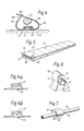
- Figure 1 shows a wall fixing primarily for use as a plant tie in plastics material such as polypropylene or polyethylene which comprises a holding member having a cup 1 and flexible ties 2 extending from opposite sides of the rim of the cup. Alternatively, the ties 2 may extend from the base of the cup 1.
- One tie has studs 3 adapted for snap- fitting engagement with corresponding holes 4 in the other tie.
- the cup 1 defines a socket 5 with a rim formed by a thin flexible skirt 6.
- a pellet of a filled hardenable adhesive composition is pushed into the socket 5 and the fixing is then pressed onto a clean hard surface so that the pellet adheres to the surface and the skirt 6 firmly engages with the surface.
- Ribs project from the inside walls of the socket 5 so as to provide a key with the pellet of the composition when it has hardened. As shown in Figure 2, the ties 2 are snapped together about a plant stem 7 once the pellet has hardened so as to support the plant stem against or adjacent to the surface of a wall 7a.
- Figure 3 shows a wall fixing 30 primarily for use as a plant tie in plastics material such as polypropylene or polyethylene which comprises a holding member having a cup portion 31 defining on one side a socket 32 having a substantially circular base 33 and a side wall 34 which tapers inwardly to the mouth of the socket. That is, the diameter of the mouth of the socket is somewhat less than the diameter of the base 33 of the socket.
- Flexible ties 35 and 36 extend from opposite sides of the cup portion 31 flush with the rim 37 of the socket which is substantially planar. Radii 31a give added strength.
- Tie 35 has an enlarged aperture 38 with a necked portion 39 at one end.
- Tie 36 has barbed projections 40 extending from its edges along its length, such that tie 36 may be passed through aperture 38 in tie 35 to fasten the two ties together such that the barbed projections 40 are retained in engagement with the necked portion 39 in a manner known per se.
- tie 35 is of shorter length than tie 36, such that when the two ties are fastened together (see Figure 4) the retention of the barbed projections 40 in the necked portion 39 is enhanced by the resilience of the ties which produces a particular outward spring action that exerts the parts together.
- a further advantage is gained wherein a series of fixings 30 may be more closely spaced in an injection mould beside each other such that the longer ties 36 and shorter ties 35 are alternately attached to the sprue (or waste plastics) so as to stagger the locations of the cup portions 31 of adjacent fixings 30 in the mould.
- sets of three fixings still attached to the sprue may be provided in a package which can result in or saving of space for packaging purposes.
- Figure 4 shows a pellet of a filled hardenable adhesive composition 41 which has been pressed into the socket 32 and then the rim 37 of the holding member has been pressed against a wall 42 such that the pellet 41 has become rock hard and has bonded to the wall.
- the pellet substantially fills the socket 32 but does not adhere to it.
- the holding member although free to swivel about the hardened pellet 41, cannot be detached therefrom by virtue of the key provided by the inwardly tapering side wall 34 of the socket 32.
- FIG 4a shows an alternative profile of the socket 32 of the fixing 30 of Figure 3, wherein the base 33 of the socket includes a domed portion extending towards the mouth of the socket.
- Figure 4b shows another alternative profile of the socket 32, including a conical portion extending towards the mouth of the socket.
- Figure 5 shows a ribbon of composition type (a) as described above including layers of an epoxide resin component 18 with a layer of mercaptan/ amine-accelerated polyamide hardener 19 encased therebetween.
- Backing sheets 20 on each side of the ribbon form a protective cover, and portions of the composition can be "torn" off along the transverse perforations 21, the backing sheets removed and a portion then mixed between the fingers to form a pellet of hardenable composition ready for use with the fixing of the present invention.
- the backing sheets are first peeled back, and portions of the composition are then torn from the ribbon.
- Individual portions are preferably identified with indicia, such as a Trade Mark, printed on the backing sheets between adjacent perforations.
- the individual portions may be provided separately in tablet form, such as small cubes complefely covered in backing material.
- FIGs 6 and 7 show an embodiment of the invention particularly suitable for use as a cable grip, e.g. for supporting electric cable on concrete or metal surfaces especially where difficulty might be encountered if standard cable grips using nails or screws were to be employed.
- the wall fixing of this embodiment is made of plastics material and comprises a cup 8 defining a socket 9 with inwardly-tapering walls similar to the socket of the plant tie illustrated in Figures 3 and 4, and a lug 10 extending from one side of the base of the cup from a hinge line 11 (shown in dashed outline in Figure 6) and adapted to interfit with a corresponding slot 12 on the opposite side of the base of the cup 8.
- the base of the cup 8 is concave and forms a channel 13 adapted to receive an electric cable.
- a pellet of a filled hardenable adhesive composition is pushed into the socket 9 and the fixing is then pressed onto a clean hard surface so that the pellet adheres to the surface.
- an electric cable 14 is placed in the channel 13, when the pellet has hardened and the lug 10 is then pressed into engagement with the slot 12 to grip the cable.
- the cable grip of this embodiment can be made to a variety of different sizes to fit standard cable sizes.
- this clasp can be used for example to fix pipework against concrete by means of the composition referred to above in awkward locations where it would be difficult to use a drill to secure known fixings which employ a screw or bolt fastener. In the case of prestressed concrete, it is inadvisable to drill holes as there is a danger of penetrating tensile steel reinforcing rods which may eventually cause the concrete to crack.
- the pipe clasp is preferably made of strong resilient plastics material.
- FIGS 9a and 9b show a fifth embodiment of the invention comprising a stud fixing 51, again preferably made of strong resilient plastics material. It includes a holding member 56 having a frusto-conical socket 53 on one side thereof for reception of a portion of a filled hardenable adhesive composition and an upwardly-tapering portion 57 extending from the socket 53. At the top of the portion 57 there is a transverse groove 58 having inwardly projecting spurs 59 defined by upstanding gripping arms 52 and 55.
- This stud fixing is adapted for supporting plastics or plastics-coated wire such that when the wire is pressed into the groove 58 it is positively retained therein (as shown in Figure 9b by virtue of the spurs 59 which allow the wire 54 to be pressed into the groove 58 but then project over the surface of the wire making it difficult to remove the wire.
- a number of the stud fixings in accordance with this embodiment may be used to support a section of plastics or plastics-coated wire mesh against a wall for use as a garden trellis for training plants.
- the portion 57 acts as a spacer, to space the trellis away from a wall in use.
- Figures 10a and 10b show a sixth embodiment of the present invention comprising a stud fixing 61, which includes a nylon holding member 64 having a socket 63 on one side as before for reception of a portion of a filled hardenable adhesive composition, and a bar 65 on the other side bridging a depression 67 formed in the holding member 64.
- the bar 65 defines an eye or aperture 66 through which a length of twine or wire or a cable-bundling strap may be passed to act as a tie.
- this stud fixing When this stud fixing is secured to a hard surface by the composition it can be used as a plant tie or a cable-bundling strap when used in conjunction with a length of twine or wire, for example plastics-coated wire for garden use, or a Thorsman nylon cable-bundling strap.
- the stud fixing 61 is suitable for heavy-duty use and nylon is the preferred material for added strength.
- Figure 11 shows a seventh embodiment of the present invention which comprises an elongate holding member 71 being a flat bar having on one side socket members 73 adjacent each end of the bar for reception of respective portions of a filled hardenable adhesive composition, and on the other side a line of upstanding loops 74 equally spaced apart along its length.
- two or more of the bars 71 may be affixed to a wall by using portions of the composition in an upright position at spaced intervals along the wall.
- Twine or garden wire is then threaded through the loops 74 between the bars to act as a support for climbing plants such as sweet pea or clematis.
- Figures 10a, 10b and Figure 11 may form a kit of parts comprising a plurality of stud or bar fixings, a plurality of portions of a filled hardenable adhesive composition together with a reel of garden wire, and users instruction.
- the embodiment of Figures 9a and 9b may form a kit of parts comprising a plurality of stud fixings, a plurality of portions of a filled hardenable adhesive composition, together with a section or sections of plastics or plastics-coated wire mesh, and users instructions.
- a wall fixing of the present invention When using a wall fixing of the present invention on unprepared surfaces, it is advisable to remove dust or loose surface material first before pressing the pellet of the filled hardenable adhesive composition with the holding member onto the surface to ensure optimum adhesion.
- a small wire brush may be optionally provided in the kit of parts for this purpose.
- the wall fixing using an epoxy adhesive is unsuitable for use on plastics surfaces to which an epoxy adhesive composition will not bond, unless the plastics surface has been coated with material to which such a composition will normally bond, for example paint.
Landscapes
- Engineering & Computer Science (AREA)
- General Engineering & Computer Science (AREA)
- Mechanical Engineering (AREA)
- Life Sciences & Earth Sciences (AREA)
- Environmental Sciences (AREA)
- Adhesives Or Adhesive Processes (AREA)
- Gripping Jigs, Holding Jigs, And Positioning Jigs (AREA)
- Electroplating Methods And Accessories (AREA)
- Analysing Materials By The Use Of Radiation (AREA)
- Supports For Pipes And Cables (AREA)
- Building Environments (AREA)
- Connection Of Plates (AREA)
- Clamps And Clips (AREA)
- Standing Axle, Rod, Or Tube Structures Coupled By Welding, Adhesion, Or Deposition (AREA)
Claims (10)
Priority Applications (1)
| Application Number | Priority Date | Filing Date | Title |
|---|---|---|---|
| AT83307882T ATE28376T1 (de) | 1983-01-03 | 1983-12-22 | Mittel zur befestigung an waenden. |
Applications Claiming Priority (4)
| Application Number | Priority Date | Filing Date | Title |
|---|---|---|---|
| IE583 | 1983-01-03 | ||
| IE5/83A IE53768B1 (en) | 1983-01-03 | 1983-01-03 | Improvements in or relating to wall fixings |
| IE114383 | 1983-05-17 | ||
| IE831143A IE831143L (en) | 1983-01-03 | 1983-05-17 | Wall fixing |
Publications (2)
| Publication Number | Publication Date |
|---|---|
| EP0115692A1 EP0115692A1 (de) | 1984-08-15 |
| EP0115692B1 true EP0115692B1 (de) | 1987-07-15 |
Family
ID=26318774
Family Applications (1)
| Application Number | Title | Priority Date | Filing Date |
|---|---|---|---|
| EP83307882A Expired EP0115692B1 (de) | 1983-01-03 | 1983-12-22 | Mittel zur Befestigung an Wänden |
Country Status (9)
| Country | Link |
|---|---|
| US (1) | US4576664A (de) |
| EP (1) | EP0115692B1 (de) |
| JP (1) | JPS59164408A (de) |
| AT (1) | ATE28376T1 (de) |
| AU (1) | AU2298983A (de) |
| BE (1) | BE898597A (de) |
| DE (1) | DE3372558D1 (de) |
| ES (1) | ES528615A0 (de) |
| IE (2) | IE53768B1 (de) |
Cited By (1)
| Publication number | Priority date | Publication date | Assignee | Title |
|---|---|---|---|---|
| USD552979S1 (en) | 2006-07-10 | 2007-10-16 | Mattel, Inc. | Packaging tie-down |
Families Citing this family (47)
| Publication number | Priority date | Publication date | Assignee | Title |
|---|---|---|---|---|
| IE53768B1 (en) * | 1983-01-03 | 1989-02-01 | Ducata Ltd | Improvements in or relating to wall fixings |
| US4706914A (en) * | 1986-07-25 | 1987-11-17 | Minnesota Mining And Manufacturing Company | Attaching assembly |
| GB2214779A (en) * | 1987-02-16 | 1989-09-13 | Kevin Ronald Ward | Bracket for securing dustbin to wall |
| JPS63151744U (de) * | 1987-03-27 | 1988-10-05 | ||
| US4759963A (en) * | 1987-05-18 | 1988-07-26 | Uso Jr Madrid | Fishing pole fastening device |
| US4897956A (en) * | 1987-10-01 | 1990-02-06 | Mcguire Robert M | Tree bracing apparatus |
| GB2214974A (en) * | 1988-02-18 | 1989-09-13 | Bowthorpe Hellermann Ltd | Cable Tie |
| US4910362A (en) * | 1988-03-14 | 1990-03-20 | Kinner Janet L | Electrical appliance with holder for securing an electrical cord |
| GB8812392D0 (en) * | 1988-05-25 | 1988-06-29 | Pettigrew A M | Tube attachment device |
| USD330324S (en) | 1990-03-27 | 1992-10-20 | Polysheet A/S | Flexible strap for fastening a tarpaulin to a scaffolding |
| US5145218A (en) * | 1990-05-30 | 1992-09-08 | Dayco Products, Inc. | Hose construction and method of making the same with adhesively bonded clamp |
| US5320461A (en) * | 1992-11-02 | 1994-06-14 | Dfm-Corporation | Fastener for air current deflector shields |
| US5685508A (en) * | 1994-01-18 | 1997-11-11 | Portable Pipe Hangers, Inc. | Pipe hanging and rooftop load supporting system |
| US5444939A (en) * | 1994-03-30 | 1995-08-29 | Cullen; Brian | Plant tie for indoor plants |
| NL9401673A (nl) * | 1994-10-11 | 1996-05-01 | Octatube Space Structures Bv | Glaspaneelbevestiging. |
| US5870621A (en) * | 1994-12-22 | 1999-02-09 | Texas Instruments Incorporated | Quadrilateral multichip computer systems and printed circuit boards therefor |
| US5637098A (en) * | 1995-08-07 | 1997-06-10 | Venetec International, Inc. | Catheter securement device |
| US5911392A (en) * | 1996-10-11 | 1999-06-15 | Greenslate; Randal S. | Retainer assembly for piping escutcheons or wall plates |
| US6228194B1 (en) * | 1998-09-14 | 2001-05-08 | Joan Cowen | Method of decorating and redecorating a ceramic tile surface |
| US6122859A (en) * | 1998-09-15 | 2000-09-26 | Filterco Enterprises Inc. | Plant tie and method |
| FR2785042B1 (fr) * | 1998-10-26 | 2001-01-05 | Abb Flakt | Surmanchette pour fixation de bouches d'extraction |
| US6290197B1 (en) * | 1999-09-10 | 2001-09-18 | Don R. Newton | Chair hold down device |
| US6588074B2 (en) | 2000-02-10 | 2003-07-08 | 3M Innovative Properties Company | Self-mating reclosable binding strap and fastener |
| FR2805009B1 (fr) * | 2000-02-16 | 2002-08-09 | Astic Injection Ind Sa | Dispositif d'attache a encliquetage d'un lien souple |
| US6472597B1 (en) * | 2000-11-22 | 2002-10-29 | Fred Robison | Fuse panel spacer |
| US20020062603A1 (en) | 2000-11-29 | 2002-05-30 | Scott Shaw | Tilt-up concrete form brace |
| GB2391256A (en) * | 2002-07-31 | 2004-02-04 | Cristian Beswick | Adjustable tie with attachment portion |
| US20050023421A1 (en) * | 2003-07-31 | 2005-02-03 | Wood Jeffrey H. | Utility bracket |
| US20050115147A1 (en) * | 2003-12-02 | 2005-06-02 | Yingfai Cheung | Method of guiding plant stem and branch growth |
| US7356884B2 (en) * | 2003-12-18 | 2008-04-15 | 3M Innovative Properties Company | Fastener for a display page |
| EP1582753A1 (de) * | 2004-03-29 | 2005-10-05 | Sika Technology AG | Befestigungselement zur Befestigung an einem Grundkörper sowie Verfahren zur Befestigung eines Befestigungselement |
| EP1740867A1 (de) * | 2004-04-30 | 2007-01-10 | L&P Property Management Company | In lordosenabstützung integrierte drahtklammer |
| US7828263B2 (en) * | 2004-07-22 | 2010-11-09 | Dayton Superior Corporation | Concrete form brace and battering wedge |
| CA2631258C (en) * | 2005-11-30 | 2013-02-19 | Mattel, Inc. | Packaging tie-downs |
| US7775603B2 (en) * | 2006-06-29 | 2010-08-17 | L & P Property Management Company | Seat suspension system and seat cushion module holder |
| US8689409B2 (en) * | 2008-07-03 | 2014-04-08 | Fastmount Limited | Panel mounting clip with adhesives |
| US9033125B2 (en) * | 2009-03-20 | 2015-05-19 | West Coast Trends, Inc. | Apparatus and method for self-stabilizing rollable luggage assembly |
| USD614941S1 (en) | 2009-03-12 | 2010-05-04 | James Murphy | Zip tie wall mount |
| US20110147541A1 (en) * | 2009-12-23 | 2011-06-23 | Caterpillar Inc. | Cable strap locating device for a wire harness and a wire harness assembly using the same |
| US8272109B2 (en) * | 2010-03-26 | 2012-09-25 | Sam Fratantoni | Device for retaining objects to surfaces |
| DE102010063076A1 (de) * | 2010-12-14 | 2012-06-14 | Airbus Operations Gmbh | Befestigungsanordnung sowie Befestigungsbeschlag zum Befestigen eines Bauteils an ein Strukturbauteil eines Luft- oder Raumfahrzeuges |
| US9366360B2 (en) * | 2013-05-14 | 2016-06-14 | A. Shane Alcorn | Cord bracket and method of use |
| EP3210757B1 (de) * | 2016-02-24 | 2019-09-11 | Airbus Operations GmbH | Verfahren zur installation einer halterung auf einer struktur mittels additiven fertigungsverfahren |
| EP3210758B1 (de) | 2016-02-24 | 2019-12-11 | Airbus Operations GmbH | Verfahren zur installation einer befestigungsvorrichtung |
| US20190380515A1 (en) * | 2018-06-15 | 2019-12-19 | Ana Teresa Azpurua Baez | Bracket Mount System |
| US12404953B2 (en) * | 2023-01-19 | 2025-09-02 | Yuxuan Shang | Drain hose restriction device for washing machine and washing machine |
| US20250318478A1 (en) * | 2023-02-16 | 2025-10-16 | Brett Littlejohn-Mifsud | Method for supporting a plant |
Family Cites Families (15)
| Publication number | Priority date | Publication date | Assignee | Title |
|---|---|---|---|---|
| DE1691401U (de) * | 1954-10-13 | 1955-01-13 | Erso Vertrieb M Adrion | Elastische befestigungsvorrichtung fuer elektrische leitungen und geraete. |
| CH416039A (de) * | 1963-05-11 | 1966-06-30 | Aluminium Press Walzwerk | Isolierbrücke aus einem kälte- und wärmehemmenden, bei Erhitzung plastisch werdenden Kunststoff |
| DE1615213A1 (de) * | 1967-06-21 | 1971-01-14 | Diehl Fa | Einrichtung zur Leistungsregelung in Heiz- und Kochgeraeten |
| US3454249A (en) * | 1967-08-07 | 1969-07-08 | Thomas & Betts Corp | Tiedown plate |
| GB1277425A (en) * | 1968-11-06 | 1972-06-14 | Exchem Holdings | Improvements in and relating to the securing of fixing elements |
| US3659319A (en) * | 1970-11-30 | 1972-05-02 | Lloyd A Erickson | Adhesive wire routing clip |
| GB1345011A (en) * | 1971-01-19 | 1974-01-30 | Santucci K E | Support structure |
| GB1345012A (en) * | 1971-01-19 | 1974-01-30 | Santucci K E | Object support device |
| US3837981A (en) * | 1971-05-10 | 1974-09-24 | T Flint | Epoxy tape |
| US3810596A (en) * | 1972-05-16 | 1974-05-14 | Minnesota Mining & Mfg | Flexible base for cable tie |
| CA993169A (en) * | 1972-11-02 | 1976-07-20 | Theodore R. Flint | Epoxy tape |
| DE2442414A1 (de) * | 1974-09-05 | 1976-03-18 | Turek Werner | Kabelschelle |
| US4025015A (en) * | 1975-08-06 | 1977-05-24 | Kolic Edwin S | Detachable article-mounting device |
| US4153156A (en) * | 1977-08-08 | 1979-05-08 | Minnesota Mining And Manufacturing Company | Method for reinforcing or sealing solid structures or for anchoring bolts therein and cartridges for use in such method |
| IE53768B1 (en) * | 1983-01-03 | 1989-02-01 | Ducata Ltd | Improvements in or relating to wall fixings |
-
1983
- 1983-01-03 IE IE5/83A patent/IE53768B1/en unknown
- 1983-05-17 IE IE831143A patent/IE831143L/xx unknown
- 1983-12-22 DE DE8383307882T patent/DE3372558D1/de not_active Expired
- 1983-12-22 EP EP83307882A patent/EP0115692B1/de not_active Expired
- 1983-12-22 AT AT83307882T patent/ATE28376T1/de active
- 1983-12-27 US US06/565,613 patent/US4576664A/en not_active Expired - Fee Related
- 1983-12-30 AU AU22989/83A patent/AU2298983A/en not_active Abandoned
-
1984
- 1984-01-02 ES ES528615A patent/ES528615A0/es active Granted
- 1984-01-03 BE BE0/212148A patent/BE898597A/fr not_active IP Right Cessation
- 1984-01-04 JP JP59000201A patent/JPS59164408A/ja active Pending
Cited By (1)
| Publication number | Priority date | Publication date | Assignee | Title |
|---|---|---|---|---|
| USD552979S1 (en) | 2006-07-10 | 2007-10-16 | Mattel, Inc. | Packaging tie-down |
Also Published As
| Publication number | Publication date |
|---|---|
| ES8506146A1 (es) | 1985-06-16 |
| US4576664A (en) | 1986-03-18 |
| ATE28376T1 (de) | 1987-08-15 |
| EP0115692A1 (de) | 1984-08-15 |
| AU2298983A (en) | 1984-07-05 |
| IE831143L (en) | 1984-07-03 |
| BE898597A (fr) | 1984-05-02 |
| ES528615A0 (es) | 1985-06-16 |
| IE53768B1 (en) | 1989-02-01 |
| JPS59164408A (ja) | 1984-09-17 |
| DE3372558D1 (en) | 1987-08-20 |
Similar Documents
| Publication | Publication Date | Title |
|---|---|---|
| US4576664A (en) | Fixing article holders to surfaces | |
| US4094068A (en) | Orthodontic bracket assembly | |
| US5009387A (en) | Object retainer for upright concrete construction forms | |
| US4830558A (en) | Adhesively securable fastener | |
| DE69835559D1 (de) | Verfahren zur Herstellung einer Zusammensetzung von wasserabsorbierenden Harzgranulaten | |
| DE69922155D1 (de) | Vorläufer einer photoempfindlichen harzzusammensetzung und verfahren zu dessen herstellung | |
| US3810596A (en) | Flexible base for cable tie | |
| JPH07173930A (ja) | コンクリート被覆材および同被覆材の型枠への仮固定方法 | |
| JP2929310B2 (ja) | コンクリート型枠用せき板の剥離具 | |
| JP2907821B1 (ja) | 養生資材の押え部材 | |
| JPS6247884B2 (de) | ||
| JPH0231017A (ja) | ポルト・ナットの防食方法 | |
| JPH02256762A (ja) | 内装下地ボードの取り付け方法 | |
| DE69828927D1 (de) | Vorrichtung zur Abgabe von Zweikomponentenklebmasse mit einem statischen Mischer | |
| JP3490810B2 (ja) | ボルト部及びナット部の防食被覆方法 | |
| JPH039722B2 (de) | ||
| JPH09235875A (ja) | 型 枠 | |
| JPS643659Y2 (de) | ||
| JPS6235761Y2 (de) | ||
| JP3041907U (ja) | ゴキブリ防除剤 | |
| JPH0718277B2 (ja) | ポールの蓋、蓋付きポールとその製造法 | |
| JP2001063752A (ja) | アンカーボルトのねじ部保護用キャップ | |
| JP2858085B2 (ja) | コーン | |
| JPS6038776Y2 (ja) | 擁壁、トンネル等に用いるマツト状排水材の取付具 | |
| JPH0672657U (ja) | 目地型 |
Legal Events
| Date | Code | Title | Description |
|---|---|---|---|
| PUAI | Public reference made under article 153(3) epc to a published international application that has entered the european phase |
Free format text: ORIGINAL CODE: 0009012 |
|
| AK | Designated contracting states |
Designated state(s): AT BE CH DE FR GB IT LI LU NL SE |
|
| 17P | Request for examination filed |
Effective date: 19850131 |
|
| GRAA | (expected) grant |
Free format text: ORIGINAL CODE: 0009210 |
|
| AK | Designated contracting states |
Kind code of ref document: B1 Designated state(s): AT BE CH DE FR GB IT LI LU NL SE |
|
| PG25 | Lapsed in a contracting state [announced via postgrant information from national office to epo] |
Ref country code: NL Effective date: 19870715 Ref country code: LI Effective date: 19870715 Ref country code: IT Free format text: LAPSE BECAUSE OF FAILURE TO SUBMIT A TRANSLATION OF THE DESCRIPTION OR TO PAY THE FEE WITHIN THE PRESCRIBED TIME-LIMIT;WARNING: LAPSES OF ITALIAN PATENTS WITH EFFECTIVE DATE BEFORE 2007 MAY HAVE OCCURRED AT ANY TIME BEFORE 2007. THE CORRECT EFFECTIVE DATE MAY BE DIFFERENT FROM THE ONE RECORDED. Effective date: 19870715 Ref country code: FR Free format text: THE PATENT HAS BEEN ANNULLED BY A DECISION OF A NATIONAL AUTHORITY Effective date: 19870715 Ref country code: CH Effective date: 19870715 Ref country code: BE Effective date: 19870715 Ref country code: AT Effective date: 19870715 |
|
| REF | Corresponds to: |
Ref document number: 28376 Country of ref document: AT Date of ref document: 19870815 Kind code of ref document: T |
|
| PG25 | Lapsed in a contracting state [announced via postgrant information from national office to epo] |
Ref country code: SE Effective date: 19870731 |
|
| REF | Corresponds to: |
Ref document number: 3372558 Country of ref document: DE Date of ref document: 19870820 |
|
| REG | Reference to a national code |
Ref country code: CH Ref legal event code: PL |
|
| EN | Fr: translation not filed | ||
| PG25 | Lapsed in a contracting state [announced via postgrant information from national office to epo] |
Ref country code: LU Free format text: LAPSE BECAUSE OF NON-PAYMENT OF DUE FEES Effective date: 19871231 |
|
| NLV1 | Nl: lapsed or annulled due to failure to fulfill the requirements of art. 29p and 29m of the patents act | ||
| PLBE | No opposition filed within time limit |
Free format text: ORIGINAL CODE: 0009261 |
|
| STAA | Information on the status of an ep patent application or granted ep patent |
Free format text: STATUS: NO OPPOSITION FILED WITHIN TIME LIMIT |
|
| 26N | No opposition filed | ||
| PGFP | Annual fee paid to national office [announced via postgrant information from national office to epo] |
Ref country code: DE Payment date: 19890131 Year of fee payment: 6 |
|
| PG25 | Lapsed in a contracting state [announced via postgrant information from national office to epo] |
Ref country code: DE Effective date: 19900901 |
|
| REG | Reference to a national code |
Ref country code: GB Ref legal event code: 732E |
|
| REG | Reference to a national code |
Ref country code: GB Ref legal event code: 732E |
|
| REG | Reference to a national code |
Ref country code: GB Ref legal event code: IF02 |
|
| PGFP | Annual fee paid to national office [announced via postgrant information from national office to epo] |
Ref country code: GB Payment date: 20021216 Year of fee payment: 20 |
|
| PG25 | Lapsed in a contracting state [announced via postgrant information from national office to epo] |
Ref country code: GB Free format text: LAPSE BECAUSE OF EXPIRATION OF PROTECTION Effective date: 20031221 |
|
| REG | Reference to a national code |
Ref country code: GB Ref legal event code: PE20 |