EP0113227A2 - Motorbetriebsmonitor und Steuerungssystem - Google Patents
Motorbetriebsmonitor und Steuerungssystem Download PDFInfo
- Publication number
- EP0113227A2 EP0113227A2 EP83307740A EP83307740A EP0113227A2 EP 0113227 A2 EP0113227 A2 EP 0113227A2 EP 83307740 A EP83307740 A EP 83307740A EP 83307740 A EP83307740 A EP 83307740A EP 0113227 A2 EP0113227 A2 EP 0113227A2
- Authority
- EP
- European Patent Office
- Prior art keywords
- engine
- cylinder
- crankshaft
- sensing
- top dead
- Prior art date
- Legal status (The legal status is an assumption and is not a legal conclusion. Google has not performed a legal analysis and makes no representation as to the accuracy of the status listed.)
- Granted
Links
- 238000002485 combustion reaction Methods 0.000 claims abstract description 87
- 239000000446 fuel Substances 0.000 claims abstract description 73
- 238000009826 distribution Methods 0.000 claims abstract description 30
- 230000008878 coupling Effects 0.000 claims description 22
- 238000010168 coupling process Methods 0.000 claims description 22
- 238000005859 coupling reaction Methods 0.000 claims description 22
- 238000011217 control strategy Methods 0.000 abstract description 4
- 238000012544 monitoring process Methods 0.000 abstract description 4
- 238000012360 testing method Methods 0.000 abstract description 3
- 238000010304 firing Methods 0.000 description 31
- 230000009471 action Effects 0.000 description 15
- 238000002347 injection Methods 0.000 description 14
- 239000007924 injection Substances 0.000 description 14
- 238000010586 diagram Methods 0.000 description 13
- 238000000034 method Methods 0.000 description 13
- 239000000203 mixture Substances 0.000 description 13
- 238000001914 filtration Methods 0.000 description 11
- 238000004519 manufacturing process Methods 0.000 description 8
- 101100181504 Mus musculus Clc gene Proteins 0.000 description 6
- 230000001133 acceleration Effects 0.000 description 5
- 238000007906 compression Methods 0.000 description 5
- 230000006835 compression Effects 0.000 description 5
- 230000008859 change Effects 0.000 description 4
- 230000007704 transition Effects 0.000 description 4
- 101100152663 Caenorhabditis elegans tdc-1 gene Proteins 0.000 description 3
- 230000001186 cumulative effect Effects 0.000 description 3
- 238000005259 measurement Methods 0.000 description 3
- 230000008569 process Effects 0.000 description 3
- 230000002829 reductive effect Effects 0.000 description 3
- 230000000979 retarding effect Effects 0.000 description 3
- 230000003044 adaptive effect Effects 0.000 description 2
- 238000013459 approach Methods 0.000 description 2
- 125000004122 cyclic group Chemical group 0.000 description 2
- 230000003247 decreasing effect Effects 0.000 description 2
- 230000001419 dependent effect Effects 0.000 description 2
- 238000013461 design Methods 0.000 description 2
- 230000000694 effects Effects 0.000 description 2
- 230000007613 environmental effect Effects 0.000 description 2
- 230000000873 masking effect Effects 0.000 description 2
- 238000009828 non-uniform distribution Methods 0.000 description 2
- 238000004439 roughness measurement Methods 0.000 description 2
- 230000036962 time dependent Effects 0.000 description 2
- 238000012935 Averaging Methods 0.000 description 1
- LFQSCWFLJHTTHZ-UHFFFAOYSA-N Ethanol Chemical compound CCO LFQSCWFLJHTTHZ-UHFFFAOYSA-N 0.000 description 1
- 230000009286 beneficial effect Effects 0.000 description 1
- 230000000903 blocking effect Effects 0.000 description 1
- 230000003750 conditioning effect Effects 0.000 description 1
- 238000013480 data collection Methods 0.000 description 1
- 230000002950 deficient Effects 0.000 description 1
- 230000000593 degrading effect Effects 0.000 description 1
- 230000003292 diminished effect Effects 0.000 description 1
- 238000009472 formulation Methods 0.000 description 1
- 229930195733 hydrocarbon Natural products 0.000 description 1
- 150000002430 hydrocarbons Chemical class 0.000 description 1
- 230000001788 irregular Effects 0.000 description 1
- 230000000670 limiting effect Effects 0.000 description 1
- 238000012986 modification Methods 0.000 description 1
- 230000004048 modification Effects 0.000 description 1
- 238000012545 processing Methods 0.000 description 1
- 238000007670 refining Methods 0.000 description 1
- 230000000630 rising effect Effects 0.000 description 1
- 238000004513 sizing Methods 0.000 description 1
- 230000035899 viability Effects 0.000 description 1
Images


Classifications
-
- F—MECHANICAL ENGINEERING; LIGHTING; HEATING; WEAPONS; BLASTING
- F02—COMBUSTION ENGINES; HOT-GAS OR COMBUSTION-PRODUCT ENGINE PLANTS
- F02D—CONTROLLING COMBUSTION ENGINES
- F02D41/00—Electrical control of supply of combustible mixture or its constituents
- F02D41/008—Controlling each cylinder individually
-
- F—MECHANICAL ENGINEERING; LIGHTING; HEATING; WEAPONS; BLASTING
- F02—COMBUSTION ENGINES; HOT-GAS OR COMBUSTION-PRODUCT ENGINE PLANTS
- F02D—CONTROLLING COMBUSTION ENGINES
- F02D41/00—Electrical control of supply of combustible mixture or its constituents
- F02D41/02—Circuit arrangements for generating control signals
- F02D41/14—Introducing closed-loop corrections
- F02D41/1497—With detection of the mechanical response of the engine
- F02D41/1498—With detection of the mechanical response of the engine measuring engine roughness
-
- F—MECHANICAL ENGINEERING; LIGHTING; HEATING; WEAPONS; BLASTING
- F02—COMBUSTION ENGINES; HOT-GAS OR COMBUSTION-PRODUCT ENGINE PLANTS
- F02P—IGNITION, OTHER THAN COMPRESSION IGNITION, FOR INTERNAL-COMBUSTION ENGINES; TESTING OF IGNITION TIMING IN COMPRESSION-IGNITION ENGINES
- F02P17/00—Testing of ignition installations, e.g. in combination with adjusting; Testing of ignition timing in compression-ignition engines
- F02P17/02—Checking or adjusting ignition timing
- F02P17/04—Checking or adjusting ignition timing dynamically
-
- G—PHYSICS
- G01—MEASURING; TESTING
- G01M—TESTING STATIC OR DYNAMIC BALANCE OF MACHINES OR STRUCTURES; TESTING OF STRUCTURES OR APPARATUS, NOT OTHERWISE PROVIDED FOR
- G01M15/00—Testing of engines
- G01M15/04—Testing internal-combustion engines
- G01M15/06—Testing internal-combustion engines by monitoring positions of pistons or cranks
-
- F—MECHANICAL ENGINEERING; LIGHTING; HEATING; WEAPONS; BLASTING
- F02—COMBUSTION ENGINES; HOT-GAS OR COMBUSTION-PRODUCT ENGINE PLANTS
- F02D—CONTROLLING COMBUSTION ENGINES
- F02D2200/00—Input parameters for engine control
- F02D2200/02—Input parameters for engine control the parameters being related to the engine
- F02D2200/10—Parameters related to the engine output, e.g. engine torque or engine speed
- F02D2200/1015—Engines misfires
-
- F—MECHANICAL ENGINEERING; LIGHTING; HEATING; WEAPONS; BLASTING
- F02—COMBUSTION ENGINES; HOT-GAS OR COMBUSTION-PRODUCT ENGINE PLANTS
- F02D—CONTROLLING COMBUSTION ENGINES
- F02D41/00—Electrical control of supply of combustible mixture or its constituents
- F02D41/008—Controlling each cylinder individually
- F02D41/0085—Balancing of cylinder outputs, e.g. speed, torque or air-fuel ratio
Definitions
- This invention relates to internal combustion engines, and more specifically to systems and techniques for monitoring the performances of the various cylinders of a multiple cylinder internal combustion engine.
- This invention also relates to feedback systems utilizing such systems and techniques not only to monitor, but also to control, the performances of the various cylinders of a multiple cylinder internal combustion engine.
- the relative combustion efficiency measure of a cylinder is a measure of the torque (or work) produced by that cylinder relative to the mean torque (or work) level of all the cylinders of the engine. Knowledge of the amount of cylinder-to-cylinder variation in the combustion efficiency is valuable for both engine diagnostic applications and engine control applications. Consistently low combustion efficiency of a given cylinder, for example, may be an indication of a defective component (a spark plug or a fuel injector, for example).
- the combustion efficiency outputs of the individual cylinders measured over a period of time may serve as a means for evaluating the effectiveness of the air/fuel delivery system in uniformly distributing the air and fuel among the cylinders. Further, a measure of the relative combustion efficiency of the various cylinders can be beneficial in increasing the overall efficiency of the engine by optimizing control settings such as, for example, ignition or injection timing, on a cylinder-by-cylinder basis.
- a system for determining the relative combustion efficiencies of the various cylinders of a multiple cylinder internal combustion engine includes means for sensing the position of the engine crankshaft, a clock for generating a time base, an interval timer for comparing the output of the clock to the output of the position-sensing means to generate a crankshaft speed-related signal, and means for coupling the crankshaft position-sensing means and clock to the interval timer. Additional means are provided for sensing -he top dead center point of the power stroke in each cylinder.
- a data processor is provided as are means for coupling the top dead center sensing means and the interval timer to the data processor to provide a plurality of data points about the top dead center. The data processor utilizes the values of those data points to calculate speed of the crankshaft about the top dead center.
- a system for controlling the performances of the individual cylinders of the multiple cylinder internal combustion engine comprises an engine ignition generator and spark distribution system, means for coupling the ignition generator and spark distribution system to the various cylinders of the engine, means for sensing engine crankshaft position, and a clock for generating a time base.
- Means are provided for sensing the top dead center point of the power stroke in each cylinder, as are means for calculating crankshaft speed and means for coupling the clock and the crankshaft position sensor to the crankshaft speed calculator. Further means are provided for calculating the combustion efficiencies of the various cylinders.
- the combustion efficiency calculating means are coupled to the clock, the crankshaft position sensor, and the means for sensing the top dead center.
- Means are provided for calculating the ignition timing of the various cylinders to match, within an acceptable margin of error, the combustion efficiencies of the various cylinders.
- the combustion efficiency calculator is coupled to the ignition timing calculator and the ignition timing calculator is coupled to the ignition generator and spark distribution system to control it.
- the combustion efficiency calculator comprises a data processor for ut.lizing the signals from the time base generator, the crankshaft position sensor, and the means for sensing the top dead center to provide a set of data points centered about the top dead center.
- a system for controlling the performances of the individual cylinders of a multiple cylinder internal combustion engine includes an engine fuel distribution system, means for coupling the fuel distribution system to the various cylinders, means for sensing the engine crankshaft position, and a clock for generating a time base.
- This system further includes means for sensing the top dead center point of the power stroke in each cylinder, means for calculating crankshaft speed, and means for coupling the clock and the crankshaft position sensor to the crankshaft speed calculator. Additional means calculate the combustion efficiencies of the various cylinders.
- Means are provided for coupling the combustion efficiency calculator to the means for sensing the top dead center, to the means for sensing the crankshaft position, and to the clock.
- Additional means are provided for calculating a fuel distribution parameter of the various cylinders to match, within an acceptable margin of error, the power outputs of the various cylinders.
- Means are provided for coupling the combustion efficiency calculator to the means for calculating the fuel distribution parameter, and means are provided for coupling the fuel distribution parameter calculator to the engine fuel distribution system.
- the fuel distribution parameter is the amount of fuel which is to be metered into each respective cylinder.
- the fuel distribution parameter is the time in the respective cylinder's operating cycle at which the fuel is metered into the cylinder.
- the mean engine speed will remain constant.
- the instantaneous engine speed will, however, undergo cyclic variations about the mean speed as a result of the energy imparted to the crankshaft during the power stroke of each cylinder.
- all of the cylinders would behave identically and produce the same amount of torque.
- the cyclic speed variations would be regular and would repeat every 720 degrees for a 4-stroke, N cylinder engine as shown in N Fig. 1.
- the cylinders do not all produce the same amount of torque and the speed variations become irregular.
- a plot of filtered instantaneous engine speed versus crankshaft angle taken from an engine on a test stand is shown in Fig. 2. The information contained on this speed plot can be used to determine the relative torque levels of the cylinders in the engine.
- the net engine torque will be the sum of the torque contributions of the individual cylinders. It can be shown, however, that over a specific portion of crankshaft rotation, the net torque can be approximated by the torque produced in one cylinder. That is, over this portion of crankshaft rotation, the contributions of the remaining N-1 cylinders may be considered negligible.
- Application of this concept to engine data indicates that the best control of engine performance can be obtained by using the crankshaft rotation from top dead center (TDC) of one cylinder to TDC of the next cylinder in the firing order. For example, in Fig. 2, the number one cylinder in the firing order reaches TDC prior to beginning the power stroke at the crankshaft angle indicated as "TDC 1".
- the next cylinder in the firing order reaches TDC 720 degrees later at TDC 2.
- the net torque produced by the engine may be approximated as the torque produced by the number 1 cylinder.
- the net engine torque may be approximated by the torque produced by that cylinder.
- ⁇ S j is defined as where S j is the instantaneous crankshaft speed at the jth top dead center, and ⁇ S j is the change in speed between successive top dead centers, then the acceleration S j between top dead center j and j+1 is given as Since engine acceleration is proportional to engine torque, a positive ⁇ S j indicates a positive net torque over the period between TDC j and TDC j+1; a negative ⁇ S j is indicative of a negative net torque. If each ⁇ S j is associated with the torque produced by the cylinder which began its power stroke at TDC j, then the relative torque contribution of each cylinder in the engine can be evaluated.
- the information necessary to calculate the combustion efficiency measure is derived from measuring the time intervals, T i for successive fixed angular rotations of the crankshaft.
- the combustion efficiency measure calculated in this manner supplies the same information as the âS k described above.
- the formulation of the combustion efficiency measure for each cylinder requires four steps:
- the basis for calculating the combustion efficiency measure is the crankshaft time interval data.
- a multitooth wheel attached to the engine crankshaft, a stationary magnetic pick-up, and a digital electronic circuit are used to count the cycles of a high frequency clock which occur during a fixed angular rotation of the crankshaft.
- the measured counts of the clock are directly proportional to the time required for the crankshaft to rotate through the known angle.
- C i is the measured counts of the high frequency clock (counts)
- f CLK the clock frequency (Hz)
- T i the time interval for the crankshaft to rotate through ⁇ degrees (seconds)
- S i the mean engine speed over the corresponding angle of rotation (RPM)
- ⁇ the angle through which the crankshaft rotates (degrees).
- the subscript i refers to the ith data point.
- FIG. 3 A plot of successive measured counts taken from an engine mounted on a test stand is shown in Fig. 3. For this case ⁇ is 6 degrees and f CLK is 5 MHz.
- the high frequency noise superimposed on the signal is a result of measurement errors, most notably variations in successive ⁇ . These variations are a result of the inaccuracies of the tooth spacing on the multitooth wheel. Such errors can be reduced by using a higher precision wheel.
- Another means of reducing the noise is by filtering the data.
- the system described makes use of an on-line, non-recursive digital filtering technique to reduce the noise.
- Fig. 4 is a plot of the same data as shown in Fig. 3 after such filtering. The filter has successfully removed the noise, while the normal engine speed fluctuations have not been diminished.
- the method for determining the relative torque contributions of each cylinder according to the invention required the instantaneous speed only at crankshaft angles corresponding approximately to top dead centers of the various cylinders. Thus, the complete speed versus crankshaft angle curve need not be considered. Likewise, for the calculation of combustion efficiency based upon crankshaft data, the complete curve is not needed.
- C Define C as the ith unfiltered data point and C i as the ith filtered data point.
- the non-recursive filtering scheme used in the control system makes use of nine unfiltered data points to calculate each filtered data point.
- a negative IP j corresponds to an increase in counts from TDC j to TDC j+1. This indicates that the engine speed has decreased in the period between successive TDC's, and that the net torque is negative.
- a positive IP i is indicative of an increase in engine speed and a positive net torque.
- the magnitude of the IP j is a measure of the change in speed over a fixed crankshaft rotation, which is proportional to the acceleration and thus to the net torque. To establish this relationship, it is noted that where S. J is the mean engine speed over the ⁇ degrees of crankshaft rotation about top dead center.
- the IP. j are a measure of the torque produced during the firing of eac.h cylinder.
- a negative IP j is indicative of a "poor" combustion event (less than average torque-producing event) while a positive IP. is indicative of a "good” combustion event (greater than average torque-producing event).
- the torque produced by a given cylinder will vary from cycle to cycle due to the variation in the combustion events in the cylinder.
- the IP. must be averaged for several successive firings.
- the combustion efficiency measure for a cylinder is defined as where IP k is the combustion efficiency measure for the kth cylinder in the firing order, IP ik is the IP for the kth cylinder on the ith firing, and M is the number of successive firings over which the IP's are to be averaged.
- the individual cylinder indices of performance, IP also form the basis for on-line roughness measurement.
- Engine roughness is a result of uneven torque production among the cylinders and variations in the torque produced in the same cylinder from cycle to cycle.
- the index of performance contains information concerning the relative torque production during each cylinder firing.
- the roughness index, R i' is defined as where
- the algerbraic sum of the individual performance indices (IP) over an integral number of engine cycles will tend to zero.
- IP performance indices
- the magnitude of the IP is a measure of the variation of the individual cylinder torque production from the mean.
- the sum of the absolute values of IP over an engine cycle is then an indication of the torque variation from cylinder to cylinder during this cycle.
- Large values for the roughness index indicate large variations in cylinder to cylinder torque production which results in increased engine roughness.
- the value for R i is a quantifiable measure of engine roughness.
- the roughness index may be used in a feedback control system such as a closed-loop idle mode controller, or as a tool for evaluating engine control strategies.
- FIG. 5 A schematic diagram of the system used for determining the relative combustion efficiency measure on a spark ignition engine is shown in Fig. 5.
- a pair of magnetic pick-ups 20, 22 are mounted in close proximity to rotating, multitooth wheels 24, 26, respectively.
- One wheel 24 is mounted to the crankshaft 30 of a multiple cylinder internal combustion engine 32. Wheel 24 is used in conjunction with the associated magnetic pick-up 20 and an associated trigger circuit 34 to generate a signal at fixed angular positions of the crankshaft 30.
- the second wheel 26 is mounted to the engine 32 distributor shaft 36. Wheel 26, the associated magnetic pick-up 22, and a trigger circuit 40 are used in generating a reference to top dead center of the beginning of the power stroke in each cylinder of engine 32.
- a clock 42 provides pulses at 5 MHz to a digital interval timer (DIT) 44.
- DIT 44 includes fourteen parallel outputs d 0 , d l9 d 2 ... d 12 , d 13 , and a V count output. V count is coupled to an input of a programmable interrupt mask (PIM) 46.
- PIM programmable interrupt mask
- Trigger circuits 34, 49 provide signal conditioning for the output signals of the magnetic pick-ups 20, 22, respectively.
- Clock 42 and DIT 44 measure the elapsed time for successive fixed angular rotations of the crankshaft 30.
- DIT 44 and PIM 46 generate and transmit signals to a microprocessor 50.
- the microprocessor 50 receives the data from the other electronic circuitry, and performs the filtering and calculations necessary to determine the relative combustion efficiency measure.
- vma g a voltage, vma g, is generated.
- V REF a reference voltage
- V trig the trigger voltage
- a low V tri g signal to the DIT 44 causes the contents of a 16-bit up-counter in the DIT 44 to be loaded in parallel into a 16-bit latch at the output of the DIT 44.
- the low V trig signal also causes the up-counter in DIT 44 to be cleared and counting of the high frequency clock pulses, V CLK' to be resumed.
- the low V tri g signal causes the V count line from the DIT 44 to the PIM 46 to go low to indicate that data is ready for processing.
- V trig goes low, depending on the state of the RESET line from the microprocessor 50 and an internal signal, the PIM 46 either transmits the "data ready” signal to the microprocessor 50 by setting the V DR line low, or blocks the "data ready” signal from the microprocessor 50 by holding the V DR line high.
- the microprocessor 50 Upon receipt of a low V DR signal, the microprocessor 50 reads the contents of the 14 least significant bits of the latch, d 0 -d 13 . This 14-bit number is proportional to the time for two successive teeth of the multitooth wheel 24 to pass the magnetic pick-up 20. After the contents of the latch are read, the microprocessor 50 toggles the V RES line to acknowledge that the data has been read. This causes the V DR line to go high. The data read by the microprocessor 50 is filtered using digital filtering. The filtered data is used to calculate a combustion efficiency measure (IP k ) for each cylinder as will be described.
- IP k combustion efficiency measure
- the second magnetic pick-up 22 mounted adjacent the distributor generates a voltage, v dist , at the passage of each lobe of the fitting 26 connected to the distributor shaft 36.
- This fitting 26 has one lobe for each cylinder of the engine 32 and is positioned such that the output of the trigger circuit, V TDC , makes a high-to-low transition coincident with the corresponding cylinder reaching TDC.
- the V TDC line remains low for approximately 60 micro-seconds and then returns high.
- the V TDC signal is used by the microprocessor 50 both to reference top dead center and, in conjunction with a clock on board the microprocessor, to determine engine 32 speed.
- the schematic of the DIT 44 circuit is shown in Fig. 6.
- the three basic components of this circuit are a timing circuit 52, an up-counter 54, and a latch 56.
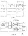
- the timing diagram for the DIT 44 is shown in Fig. 7.
- the Vtrig signal is the input to the timing circuit 52 .
- the outputs of circuit 52 are V clr , V latch , and V count .
- the timing circuit 52 On the falling edge 57 of the V tri g signal (Fig. 7), the timing circuit 52 generates a pulse 58 (Fig. 7) of approximately 75 n-sec duration on the V latch line.
- the contents of the up-counter 54 are loaded in parallel into the 16-bit latch 56, and appear at the output d 0 , ... d 13 ... of the latch 56.
- the falling edge 62 (Fig.
- a 75 n-sec positive pulse 64 appears on the V clr line, causing the up-counter 54 to be reset at zero. Counting resumes when'the V clr line goes low at the end of the pulse 64. Also on the falling edge 62 of the V latch pulse, the V count line goes low, at 66 in Fig. 7, for approximately 8.8 u-sec.
- the PIM 46 has two functions, one to mask from the microprocessor 50 that data which is not needed in calculating the combustion efficiency measure, and also to hold the data ready line, V DR , low until the data has been read by the microprocessor 50.
- a wheel 24 having sixty teeth is used.
- twenty data points are measured for each engine firing (sixty teeth per revolution divided by three cylinders firing per revolution). Since nine data points per firing are used by the microprocessor 50 to calculate the combustion efficiency measure, eleven unneeded data points are successively latched onto the output d 0 ... d l3 of the DIT 44 for each firing.
- the PIM 46 prevents the data ready signal VDR corresponding to these unnecessary data points from being transmitted to the microprocessor 50, thus allowing the microprocessor 50 to continue program execution without undue interruptions.
- the inputs to the PIM 46 are V count , V RES' and RESET.
- the output is V DR .
- the ENABLE line is held high, blocking the V count signals from being transmitted to the S input of a SET-RESET flip-flop 74. This causes the V DR line to be held high.
- the ENABLE line becomes active (low) when either the RESET line from the microprocessor 50 (Fig. 5) is brought high, or the C fin line goes low.
- a low ENABLE causes the V count signals to be transmitted to the flip-flop 74.
- the output of the flip-flop 74, V DR goes low and remains low until the R input, V RES , is brought active low by the microprocessor 50.
- a 4-bit binary counter 76 is used in the PIM 46 to keep track of the number of data points being masked from the microprocessor 50.
- the counter 76 is disabled and the outputs q 0 -q 3 , are held at zero. Once the RESET line is brought low, the counter 76 is enabled.
- the output, C fin , of a four-bit binary comparator circuit 78 is low whenever the output q 0 -q 3 of the binary counter 76 matches the four-bit binary word c 0 -c 3 which is entered via a set of switches (not shown).
- This binary word c 0 -c 3 sets the number of data points that will be masked from the microprocessor 50 following the high-to-low transition of the RESET line.
- the comparator 78 output, C fin will be high. This enables the V count signal to be transmitted to the input of the counter 76 through an AND gate 80.
- the binary counter 76 increments by one for each high-to-low transition of the V count line.
- the output 90-93 of the counter 76 matches the value set by c 0 -c 3 , the C fin line will go low. This causes the ENABLE line to become active and permits subsequent V count pulses to be transmitted to the flip-flop 74. Simultaneously, further pulses of V count are blocked from the input of the counter 76 by the low condition of the C fin line and AND gate 80 input coupled to Cfin, until the counter 76 is cleared by a high signal from the RESET line.
- the microprocessor 50 activates the RESET line, thus enabling the V count pulses to be transmitted through the PIM 46.
- V TDC as a reference to TDC
- the microprocessor 50 synchronizes the data-taking operations with the crankshaft 30 position. This is done by counting the number of V DR pulses following the first V TDC pulse.
- the microprocessor 50 begins to read the data from the DIT 44 output d 0 -d 13 on each V DR pulse. Nine data points are read, and then the microprocessor 50 brings the RESET line low to mask the next 11 data points. This is illustrated in the timing diagram in Fi g . 9.
- the next 11 Vcount pulses are masked from the microprocessor 50 by the PIM 46.
- C fin goes low enabling the V DR line. That is, the twelfth pulse of V count is transmitted to the microprocessor 50 on the V DR line.
- V DR pulse the microprocessor 50 sets the RESET line high and holds it high until nine more data points have been read. The RESET line is then brought low to again initiate the masking operation. This process is repeated as long as the program is in operation.
- the optimum ignition timing in spark ignition engines or optimum injection timing in diesel engines for the efficient combustion of an air/fuel mixture is a function of, among other parameters, the mass of fuel and the ratio of air to fuel in the cylinder.
- the controls described herein adjust the timing to each cylinder independently, thus compensating for the non-uniform distribution of air and fuel among the cylinders.
- the timing is set for the most efficient combustion of the mixture in each cylinder.
- Engine crankshaft speed information is used to calculate a relative combustion efficiency measure for each cylinder. This combustion efficiency measure is used as the basis for adjusting the timing to the individual cylinders. As the composition of the combustible mixture to the cylinders changes with changing engine operating conditions, the control continues to adjust the timing for optimum combustion.
- FIG. 10 A block diagram illustration of a control system implemented on a spark ignition engine is shown in Fig. 10.
- the engine 84 cranshaft position, CR as a function of time is used by a combustion efficiency measure calculation system 86 to derive a relative combustion efficiency measure (IP k ) for each cylinder in engine 84.
- An engine speed calculation system 88 uses the crankshaft position CR as a function of time to calculate the mean engine speed, S, to generate a reference to top dead center, TDC , and to index the cylinder position in the firing order, CYL k .
- An ignition timing system 90 determines the optimum spark advance for each cylinder based on the combustion efficiency measure IP k from system 86 and the mean engine speed S from system 88.
- the cylinder index, CYL k' mean engine speed, S, and top dead center reference, TDC are used to time the ignition signal, V SA , transmitted to the ignition coil driver and spark distribution system 92 to assure the proper spark advance to each cylinder of engine 84.
- a clock 94 generates the time base for the time-dependent functions of systems 86, 88.
- Fig. 11 The implementation of this control on a compression ignition engine is illustrated in Fig. 11.
- the fuel injection timing, FP k , to each cylinder, CYL k' is the controlled variable.
- the engine 98 crankshaft position, CR as a function of time is used by a combustion efficiency measure calculation system 100 to derive a relative combustion efficiency measure (IP k ) for each cylinder in engine 98.
- An engine speed calculation system 102 uses the crankshaft position, CR , as a function of time to calculate the mean engine speed, S, to generate a reference to top dead center, TDC , and to index the cylinder position in the firing order, CYL k .
- a fuel parameter (in this case, injection timing) system 104 determines the optimum fuel injection timing for each cylinder in engine 98 based on the combustion efficiency measure IP k and the mean engine speed S .
- the cylinder index, CYL k , mean engine speed, S, and top dead center reference, TDC are used to time the fuel injection signal, V FP , transmitted to the fuel distribution system 106 to k assure the proper fuel injection timing to each cylinder.
- the fuel system parameter FP k controlled could also be fuel amount injected (controlled, for example by injector nozzle open time or fuel system pressure adjustment), or some combination of fuel injection timing and amount of fuel injected.
- Another control strategy using the inventive control system makes use of the fact that the fuel consumed by an idling engine is proportional to the engine speed - the lower the speed, the less fuel used. However, as the engine speed is lowered, the engine tends to run rougher. The optimum engine idle speed is the lowest speed at which the roughness is not objectionable. This speed changes with both engine operating and environmental conditions.
- An adaptive idle speed control system is based upon the system described above.
- the idle mode control system is shown in Fig. 12.
- the idle control seeks to maintain the lowest engine speed consistent with a preset desired engine roughness level, R d , under any combination of engine operating and environmental conditions.
- the speed is controlled by manipulating the throttle via associated control and power circuitry (throttle actuator).
- the engine crankshaft position, CR as a function of time is used by a relative torque calculation system to derive the index of performance (IP ik ) for each firing of each cylinder in the engine.
- IP ik index of performance
- a roughness measure calculating system uses the IP ik to derive a roughness index, R i , for each engine cycle. This roughness index is then filtered to produce the measured engine roughness, R.
- the speed set-point calculating system compares the measured engine roughness with a preset roughness set-point, R d , and adjusts the speed set-point, S d , to reduce the error between R d and R m .
- An engine speed calculating system uses the crankshaft position as a function of time to calculate the mean engine speed, S, to generate a reference to top dead center, TDC , and to index the cylinder in the firing order.
- a speed control system filters the mean engine speed to determine a measured engine speed S m .
- the measured engine speed and speed set-point are compared.
- the throttle actuating signal, u THS is determined in such a way as to reduce any error between the measured engine speed and speed set-point.
- the throttle actuator translates the electronic signal from the speed control unit into actual throttle motion, ⁇ TH .
- An ignition timing system uses the mean engine speed, S , top dead center reference signal, TDC , and cylinder index CYL k to time the signal, V SA , transmitted to the ignition coil drive and spark distribution system to assure proper spark advance to each cylinder of the engine.
- the roughness measurement system may generate a throttle actuator signal, u THE , to initiate emergency throttle action in the event that the engine is about to stall.
- This emergency throttle action signal is based upon the individual cylinder index of performance and gives a much earlier indication of sudden drops in speed than the measured engine speed value, S .
- the desired roughness set-point, R d is modified based on the frequency with which emergency action is required.
- the need for frequent emergency action indicates that the engine is operating in a region very near the point where it will stall. This condition suggests that the roughness set-point has been set too high.
- the frequency with which emergency action is initiated exceeds a limiting value, the roughness set-point is decreased.
- an improved knock control scheme uses the concept of controlling the ignition timing to each cylinder independently.
- the usual corrective action for an engine which is knocking is to retard the ignition timing to all cylinders until the knock level is within acceptable limits.
- the retarded ignition timing causes a loss of power in the engine.
- not all cylinders are simultaneously knocking.
- the knock detected may be due to but one of the cylinders.
- the inventive control system the specific cylinder or cylinders th--t are knocking are identified. Then the ignition timing to these cylinders alone is retarded, resulting in less power loss than if the ignition timing were retarded to all cylinders.
- retarding the ignition timing in general results in lower emission levels.
- retarded ignition timing also causes poorer engine performance and fuel efficiency.
- the ignition timing is retarded selectively to the individual cylinders.
- the control system described herein can employ the lean burn control strategy by continually seeking the mixture ratio just richer than the lean limit.
- the mixture ratio is continually driven leaner while the combustion efficiency measure is calculated and used to detect the onset of misfire.
- the control system continues to seek the new lean limit.
- the properties of the fuel used in an engine have a significant effect on the performance of the engine.
- the controls such as ignition timing, air/fuel ratio, or fuel injection timing, for optimum operation in terms of fuel economy, emission levels, and performance are dependent on the properties of the fuel used.
- the control system described adjusts the ignition timing to the optimum value for the particular fuel used.
- the timing of fuel injection and quantity of fuel injected are adjusted. Thus, compensation is provided for the normal variations in the properties of a given grade of fuel that occur as a result of the refining process.
- control technique described is extended directly to permit different grades of fuel to be burned in a given engine without modification to that engine. This permits the engine to be operated on a range of fuels without loss of performance.
- the operator of a vehicle is free to choose from, for example, unleaded gasoline or gasahol with varying alcohol contents, dependent on local availability.
- the control system Independent of the fuel used, the control system adjusts the ignition timing to the optimum value.
- combustion efficiency measure is used as a tool for on-line engine diagnostics.
- the combustion efficiency measure is an indication of the performance of each cylinder relative to the other cylinders. Identification of a cylinder with consistently poor performance under all operating conditions may signify, for example, that the spark plug in that cylinder is not firing (in a spark ignition engine). Similarly, in a compression ignition engine, a cylinder which shows a combustion efficiency measure consistently below the average may indicate a malfunctioning fuel injector.
- the combustion efficiency measure can also be used in evaluating designs of air/fuel delivery systems for engines. For optimum operation, the air/fuel delivery system should distribute the air and fuel evenly among the cylinders. Uneven distribution of the air and fuel results in uneven torque production among the cylinders. Since the combustion efficiency measure is an indication of the relative torque production level of each cylinder, variations in the combustion efficiency measure among the cylinders are useful as a measure of the distribution.
- Fig. 12 The implementation of this control on a spark ignition engine is illustrated in Fig. 12.
- the engine 110 crankshaft position, O CR is used by a combustion efficiency measure calculation system 112 to derive a relative combustion efficiency measure (IP ik ) for each cylinder in engine 110.
- An engine speed calculation system 114 uses the crankshaft position O CR as a function of time to calculate the mean engine speed, S, to generate a reference to top dead center, O TDC , and to index the cylinder position in the firing order, CYL k .
- An ignition timing system 116 determines the optimum spark advance for each cylinder based on the crankshaft position, the top dead center reference, and the cylinder position in the firing order from engine speed calculation system 114. The ignition timing system 116 supplies this information to an ignition coil driver and spark distribution system 118 to assure proper spark advance to each cylinder of engine 110.
- a clock 120 generates the time base for the time-dependent functions of systems 112, 114.
- the roughness measure calculating system 122 of the present invention uses the indices of performance, IPik, to derive the roughness index which is filtered to provide the measure R , measured engine roughness.
- the engine roughness measure calculation system 122 provides an emergency throttle control signal u THE , based upon the individual cylinders' indices of performance.
- the signal u THE provides an essentially immediate indication that emergency throttle action is necessary to prevent the engine 110 from stalling.
- the signal R is passed to a speed set-point calculation system 124 wherein the measured roughness is compared with a continuously updated desired roughness set-point signal R d .
- the desired speed output signal S d from the speed set-point calculation system 124 is supplied to an engine speed control comparator 126 wherein it is compared to the mean engine speed signal, S, provided by the engine speed calculation system 114.
- a non-emergency throttle control signal u THS is provided by the speed control 126.
- the signal, u THS' is summed in a summer 128 with the emergency throttle control signal u THE provided by the roughness measure calculating system 122 to generate the throttle actuator signal u TH which is fed back to the throttle actuator 130 of the system.
- the output 0 ⁇ TH throttle position, provided by throttle actuator 130, controls the position of the engine 110 throttle.
- Fig. 13 illustrates a generalized form for the program control flow chart.
- the program enters a background routine.
- the background routine for an engine performance controller constructed in accordance with the present invention is illustrated in Fig. 14a.
- the program waits for interrupts to go to a filter sub-routine.
- the program is in the filter sub-routine or one of its related sub-routines when the engine is under the control of the engine performance controller.
- the background routine for an engine performance monitor constructed according to the present invention is illustrated in Fig. 14m.
- the program continuously scans a command keyboard for inputs which are basically commands for certain data to be outputted onto a CRT or screen. Upon the occurrence of such a command, the data requested is output to the screen, and the background routine returns to the scan mode.
- Fig. 14a or Fig. 14m cause the program to enter a filter sub-routine, FILT, flow-charted at Fig. 14b.
- FILT filter sub-routine
- a data point is first read and multiplied by a filter coefficient.
- the program determines whether the last data point read is the last (ninth) data point to be read during the current combustion event. If it is not, a data point counter is incremented and the program returns to await the next data point. If the last data point read is the ninth data point, the counter is cleared and the nine data points centered about top dead center are used to calculate the index of performance. This is done by an index of performance sub-routine noted in the general flow chart of Fig. 13.
- the index of performance sub-routine is as illustrated in Figs. 14c-d.
- the index of performance sub-routine reaches a decision block in which the index of performance is compared to an unacceptable engine roughness level RUFEMG.
- An individual cylinder index performance not greater than RUFEMG causes the emergency counter EMGCNT to be incremented.
- EMGCNT is the number of successive cylinders in the firing order with indices of performances algebraically less than RUFEMG, the roughness level requiring emergency throttle action.
- EMGCNT is compared to the emergency count limit, EMGLIM.
- EMGLIM is the number of successive "bad" cylinder firings needed to initiate emergency throttle action. If EMGCNT has reached the EMGLIM limit, the emergency flag EMGFLG is set, the cumulative emergency counter EMGSUM is incremented, and the throttle control output u THIN is set equal to EMGTH, after which a control signal is output to the throttle actuator through the throttle actuator control sub-routine illustrated in Figs. 14j-141.
- EMGCNT is then set to 0, the index of performance of the cylinder is stored and its absolute value added to the sum of the absolute magnitudes of the indices of performance of the various cylinders.
- the program asks whether the last cylinder whose index of performance was stored was the last cylinder in the firing order. If it was not, the sub-routine returns to begin the data collection and index of performance calculation process for the next cylinder. If the last cylinder whose index of performance was calculated was the last cylinder in the firing order, a counter OPCNT is incremented.
- OPCNT is compared to OPCYC. If OPCNT does not equal OPCYC, the program returns to receive data relative to the next cylinder's index of performance. If OPCNT equals OPCYC, the program executes the closed-loop control sub-routine illustrated in Fig. 13 and at Figs. 14e-14g.
- EMGCNT is set to 0, and the index of performance of the cylinder is stored and its absolute value added to the sum of the absolute magnitudes of the indices of performance.
- the closed-loop control program routine is illustrated in Fig. 13 and in detail in Figs. 14e, 14f, and 14g.
- the program enters this routine and calculates and filters, in order, mean speed and roughness index.
- the mean speed calculation and filtering sub-routine SPCF is used to calculate and filter mean engine speed.
- the roughness index calculation and filtering sub-routine RCF is used to calculate and filter the roughness index.
- a roughness loop counter is then incremented. If EMGFLG, an emergency flag, is clear, the program then compares the count in this COUNTER to RUFCNT.
- EMGFLG is clear and COUNTER is less than RUFCNT
- the program goes to Fig. 14g to calculate the speed error E s which equals the idle speed set-point S d minus the filtered engine mean speed S m .
- the program determines the control output u THIN' the control output to the throttle actuator. This control output is the number of stepper motor control steps that the throttle actuator control is commanded to move.
- the control signal is next output to the throttle actuator.
- the emergency flag EMGFLG is then cleared and the system returns to the control of the index of performance (IPSUB) sub-routine.
- COUNTER is not less than RUFCNT, the counter is cleared.
- the closed-loop control program sub-routine continues with the decision block, IS EMGSUM ⁇ SUMLIM? If the answer is no, the roughness set point R d (Fig. 12), or RUFMAX (Fig. 14f), is reduced. The new value of RUFMAX is then stored. If EMGSUM is less than SUMLIM, or after the new value of RUFMAX is stored, EMGSUM is reset to 0. Then, the new speed set-point S d is calculated. Referring to Fig. 14g, the decision is made whether S d is less than Sdul. S dul is the idle speed set-point upper limit.
- S d is not less than S dul .
- S d is set equal to S dul .
- the program calculates the speed error, E s , which is set equal to S d - S m .
- the program determines the control output u THIN , the control output to the throttle actuator.
- the control signal is next output to the throttle actuator.
- the emergency flag EMGFLG is then cleared, and the system returns to the control of the index of performance sub-routine.
- S d is the idle speed set-point lower limit. This is the lowest admissible idle speed set-point. If S d is greater than Sdll, the program proceeds to a calculation of the speed error E s , and continues in the manner previously described. If S d is not greater than S dll , then S d is set equal to S dll . The program then proceeds to a calculation of the speed error E and continues in the manner described above.
- the roughness calculation and filter sub-routine is illustrated in Fig. 14h.
- the sum of the absolute magnitudes of the indices of performance is obtained over the speed loop update interval OPCYC.
- the sum of the absolute magnitudes of the indices of performance is reset to 0, and the roughness index R is calculated as discussed previously.
- the roughness index is stored, filtered, and the filtered roughness index is stored, and the program returns from the RCF sub-routine to CLCP sub-routine (Fig. 13).
- the mean engine speed calculation and filtering sub-routine SPCF is illustrated in Fig. 14i.
- the total number of clock counts in the OPCYC engine cycles, or OPCYC speed-loop update interval, are read, and the OPCYC clock count is reset to 0.
- the mean number of clock counts per engine cycle is then calculated.
- This sub-routine then converts the clock counts per cycle to equivalent mean engine speed (rpm).
- This mean engine speed is then filtered and stored, and the program returns from the SPCF sub-routine to the CLCP sub-routine (Fig. 13).
- the throttle actuator control sub-routine TAC is illustrated in Figs. 14j-141.
- the output address for the throttle actuator control circuit is first set.
- an open throttle/close throttle flag is set to open.
- the sub-routine then reads in a desired number of control steps, u THIN . This is the control output to the throttle actuator, or the number of stepper motor control steps that the throttle actuator control is commanded to move.
- u THIN is compared to 0. As illustrated in Fig. 14 1, if u THIN equals 0, the number of control steps sent to the throttle actuator control is stored and the program returns from the TAC sub-routine to the CLCP sub-routine.
- u THIN does not equal 0, the TAC sub-routine reaches the next decision block, u THIN > 0? If u THIN is greater than 0, as best illustrated in Fig. 14k, the throttle actuator enable line is strobed high. An open throttle/close throttle signal is sent to the throttle actuator control.
- the absolute magnitude of u THIN is compared to u THMAX , the maximum allowable throttle command. If the absolute magnitude of u THIN is not less than u THMAX , then u THIN is set equal to u THMAX . If the absolute magnitude of u THIN is less than u THMAX' this sub-routine continues as illustrated in Fig. 141.
- the control step output to the throttle actuator control circuit is sent.
- the throttle actuator control enable line is strobed low to initiate throttle motion. The number of control steps sent to the throttle actuator control is stored, and the program returns from the TAC sub-routine to CLCP sub-routine.
- u THIN is not greater than 0
- the open throttle/close throttle flag is reset to close ( F ig. 14k). Then the absolute magnitude of u THIN is calculated, and the throttle actuator enable line is strobed high. An open throttle/close throttle signal is sent to the throttle actuator control. Then the sub-routine continues with the comparison of the absolute magnitude of u THIN to u THMAX and the remainder of the TAC sub-routine as previously discussed.
Landscapes
- Engineering & Computer Science (AREA)
- Chemical & Material Sciences (AREA)
- Combustion & Propulsion (AREA)
- Mechanical Engineering (AREA)
- General Engineering & Computer Science (AREA)
- Physics & Mathematics (AREA)
- General Physics & Mathematics (AREA)
- Combined Controls Of Internal Combustion Engines (AREA)
- Testing Of Engines (AREA)
- Electrical Control Of Ignition Timing (AREA)
- Electrical Control Of Air Or Fuel Supplied To Internal-Combustion Engine (AREA)
Applications Claiming Priority (2)
| Application Number | Priority Date | Filing Date | Title |
|---|---|---|---|
| US06/452,372 US4532592A (en) | 1982-12-22 | 1982-12-22 | Engine-performance monitor and control system |
| US452372 | 1982-12-22 |
Publications (3)
| Publication Number | Publication Date |
|---|---|
| EP0113227A2 true EP0113227A2 (de) | 1984-07-11 |
| EP0113227A3 EP0113227A3 (en) | 1985-08-28 |
| EP0113227B1 EP0113227B1 (de) | 1989-05-31 |
Family
ID=23796208
Family Applications (1)
| Application Number | Title | Priority Date | Filing Date |
|---|---|---|---|
| EP83307740A Expired EP0113227B1 (de) | 1982-12-22 | 1983-12-20 | Motorbetriebsmonitor und Steuerungssystem |
Country Status (4)
| Country | Link |
|---|---|
| US (1) | US4532592A (de) |
| EP (1) | EP0113227B1 (de) |
| JP (1) | JPH0631562B2 (de) |
| DE (1) | DE3379976D1 (de) |
Cited By (8)
| Publication number | Priority date | Publication date | Assignee | Title |
|---|---|---|---|---|
| EP0178058A2 (de) * | 1984-09-01 | 1986-04-16 | Kawasaki Jukogyo Kabushiki Kaisha | Regler für Verbrennungsmotor |
| GB2169958A (en) * | 1984-12-28 | 1986-07-23 | Fuji Heavy Ind Ltd | System for controlling the ignition timing of an internal combustion engine |
| EP0198137A2 (de) * | 1985-04-15 | 1986-10-22 | Purdue Research Foundation | Direkte Messung des Motordrehmoments und seiner Schwankungen für die Motorsteuerung unter Benutzung der Kurbelwellen-Geschwindigkeitsschwankungen |
| FR2605056A1 (fr) * | 1986-10-08 | 1988-04-15 | Lucas Ind Plc | Appareillage de commande d'alimentation en carburant pour un moteur a cylindres multiples |
| DE3810750A1 (de) * | 1987-04-10 | 1988-10-27 | Volkswagen Ag | Brennkraftmaschine mit mehreren drosseln in der saugrohranordnung |
| FR2699604A1 (fr) * | 1992-12-19 | 1994-06-24 | Bosch Gmbh Robert | Procédé de détection de défaut d'étanchéité des injecteurs d'un moteur thermique. |
| US5544636A (en) * | 1993-12-16 | 1996-08-13 | Volkswagen Ag | Method for obtaining trigger signals to regulate energy conversion in the combustion chamber of an internal combustion engine |
| WO1998007971A2 (de) * | 1996-08-16 | 1998-02-26 | Temic Telefunken Microelectronic Gmbh | Verfahren zur zylinderselektiven steuerung einer selbstzündenden brennkraftmaschine |
Families Citing this family (68)
| Publication number | Priority date | Publication date | Assignee | Title |
|---|---|---|---|---|
| DE3421640A1 (de) * | 1983-06-10 | 1985-01-31 | Diesel Kiki Co. Ltd., Tokio/Tokyo | Einrichtung zum feststellen des aenderungswertes in der drehzahl eines verbrennungsmotors |
| JPH0733809B2 (ja) * | 1984-06-27 | 1995-04-12 | 株式会社日本自動車部品総合研究所 | 内燃機関の出力変動測定方法 |
| DE3429525A1 (de) * | 1984-08-10 | 1986-02-20 | Robert Bosch Gmbh, 7000 Stuttgart | Verfahren zur zylindergruppenspezifischen regelung einer mehrzylindrigen brennkraftmaschine und vorrichtung zur durchfuehrung des verfahrens |
| JPS61234270A (ja) * | 1985-04-10 | 1986-10-18 | Japan Electronic Control Syst Co Ltd | 内燃機関のアイドル制御装置 |
| JPS61255273A (ja) * | 1985-05-07 | 1986-11-12 | Japan Electronic Control Syst Co Ltd | 内燃機関のアイドル制御装置 |
| JPS62666A (ja) * | 1985-06-25 | 1987-01-06 | Japan Electronic Control Syst Co Ltd | 内燃機関のアイドル制御装置 |
| JPH0353001Y2 (de) * | 1985-07-03 | 1991-11-19 | ||
| JPH0833143B2 (ja) * | 1987-02-23 | 1996-03-29 | 三菱電機株式会社 | エンジンの制御装置 |
| US4843580A (en) * | 1987-06-24 | 1989-06-27 | Delco Electronics Corporation | Noise immune crankshaft pulse position developing apparatus |
| DE3724420A1 (de) * | 1987-07-23 | 1989-02-02 | Audi Ag | Verfahren zum schutz eines abgaskatalysators einer mehrzylinder-brennkraftmaschine mit fremdzuendung |
| US4907176A (en) * | 1988-01-27 | 1990-03-06 | Sun Electric Corporation | Flag generation system |
| US4962470A (en) * | 1988-08-01 | 1990-10-09 | Delco Electronics Corporation | Crankshaft pulse position developing apparatus having a synchronous digital filter |
| KR930009907B1 (ko) * | 1988-10-04 | 1993-10-13 | 미쯔비시 덴끼 가부시끼가이샤 | 내연기관 제어장치 |
| JPH0315645A (ja) * | 1989-06-13 | 1991-01-24 | Hitachi Ltd | エンジン制御装置 |
| DE3932636C2 (de) * | 1989-09-29 | 1999-09-23 | Bosch Gmbh Robert | Geschwindigkeitsregler/-begrenzer |
| EP0437057B1 (de) * | 1990-01-08 | 1993-11-03 | Hitachi, Ltd. | Methode und Gerät um den Verbrennungszustand in einer mehrzylindrigen Brennkraftmaschine zu detektieren |
| DE4001333C1 (en) * | 1990-01-18 | 1991-10-10 | Audi Ag, 8070 Ingolstadt, De | Cylinder-selective energy conversion monitoring of IC engine - k ascertaining instantaneous RPM and forming quadrant during stroke of each cylinder over certain crankshaft angle of rotation |
| EP0442687B1 (de) * | 1990-02-14 | 1998-04-15 | Lucas Industries Public Limited Company | Vorrichtung zur Detektierung von Fehlzündungen |
| US5278760A (en) * | 1990-04-20 | 1994-01-11 | Hitachi America, Ltd. | Method and system for detecting the misfire of an internal combustion engine utilizing engine torque nonuniformity |
| US5200899A (en) * | 1990-04-20 | 1993-04-06 | Regents Of The University Of Michigan | Method and system for detecting the misfire of an internal combustion engine utilizing angular velocity fluctuations |
| US5239473A (en) * | 1990-04-20 | 1993-08-24 | Regents Of The University Of Michigan | Method and system for detecting the misfire of an internal combustion engine utilizing angular velocity fluctuations |
| JPH0472449A (ja) * | 1990-07-10 | 1992-03-06 | Fuji Heavy Ind Ltd | エンジンの失火診断装置 |
| US5044195A (en) * | 1990-08-24 | 1991-09-03 | Ford Motor Company | Misfire detection in an internal combustion engine |
| US5109695A (en) * | 1990-08-24 | 1992-05-05 | Ford Motor Company | Misfire detection in an internal combustion engine |
| US5056360A (en) * | 1990-08-24 | 1991-10-15 | Ford Motor Company | Selection of velocity interval for power stroke acceleration measurements |
| GB2251499A (en) * | 1991-01-05 | 1992-07-08 | Delco Electronics Corp | Electronic control module. |
| JP2564427B2 (ja) * | 1991-01-14 | 1996-12-18 | 三菱電機株式会社 | 内燃機関失火検出方法及び装置 |
| GB9102232D0 (en) * | 1991-02-01 | 1991-03-20 | Lucas Ind Plc | Method of and apparatus for processing internal combustion engine speed data |
| DE4122139C2 (de) * | 1991-07-04 | 2000-07-06 | Bosch Gmbh Robert | Verfahren zur Zylindergleichstellung bezüglich der Kraftstoff-Einspritzmengen bei einer Brennkraftmaschine |
| US5699252A (en) * | 1992-03-30 | 1997-12-16 | Purdue Research Foundation | Error correction in measures of speed, acceleration, misfire detection and roughness |
| US5361629A (en) * | 1992-08-21 | 1994-11-08 | Chrysler Corporation | Single sensor misfire detection apparatus and method for an internal combustion engine |
| CA2104144C (en) * | 1992-08-21 | 2004-01-06 | Jay C. Mccombie | Dual sensor misfire detection apparatus and method for an internal combustion engine |
| CA2081080C (en) * | 1992-10-23 | 1998-08-11 | Philippe Gaultier | Method for the detection of reciprocating machine faults and failures |
| US5345817A (en) * | 1993-02-22 | 1994-09-13 | General Motors Corporation | Misfire detection in internal combustion engines |
| US5509302A (en) * | 1994-05-02 | 1996-04-23 | Saturn Corporation | Misfire detection in internal combustion engines |
| US5602331A (en) * | 1995-06-06 | 1997-02-11 | Chrysler Corporation | Engine misfire detection with cascade filter configuration |
| US5574217A (en) * | 1995-06-06 | 1996-11-12 | Chrysler Corporation | Engine misfire detection with compensation for normal acceleration of crankshaft |
| US5544521A (en) * | 1995-06-06 | 1996-08-13 | Chrysler Corporation | Engine misfire detection with rough road inhibit |
| US5633456A (en) * | 1995-08-04 | 1997-05-27 | Chrysler Corporation | Engine misfire detection with digital filtering |
| DE19534996A1 (de) * | 1995-09-21 | 1997-03-27 | Bosch Gmbh Robert | Verfahren zur Verbrennungsaussetzererkennung durch Auswertung von Drehzahlschwankungen |
| US5771482A (en) * | 1995-12-15 | 1998-06-23 | The Ohio State University | Estimation of instantaneous indicated torque in multicylinder engines |
| US6070567A (en) * | 1996-05-17 | 2000-06-06 | Nissan Motor Co., Ltd. | Individual cylinder combustion state detection from engine crankshaft acceleration |
| US6199007B1 (en) * | 1996-07-09 | 2001-03-06 | Caterpillar Inc. | Method and system for determining an absolute power loss condition in an internal combustion engine |
| US5824890A (en) * | 1996-08-01 | 1998-10-20 | Chrysler Corporation | Real time misfire detection for automobile engines |
| US5753804A (en) * | 1996-08-01 | 1998-05-19 | Chrysler Corporation | Spatial frequency implemented digital filters for engine misfire detection |
| US5717133A (en) * | 1996-11-22 | 1998-02-10 | Chrysler Corporation | Mixed sampling rate processing for misfire detection |
| US5862507A (en) * | 1997-04-07 | 1999-01-19 | Chrysler Corporation | Real-time misfire detection for automobile engines with medium data rate crankshaft sampling |
| US5921221A (en) * | 1998-05-08 | 1999-07-13 | Ford Global Technologies, Inc. | Method of controlling cyclic variation in engine combustion |
| US6223120B1 (en) | 1998-11-19 | 2001-04-24 | Jeremy Williams | Cylinder torque estimation using crankshaft angular response measurements |
| DE10015162B4 (de) * | 1998-11-24 | 2019-08-01 | Scania Cv Ab | Anordnung und Verfahren zum Kalibrieren und/oder Überwachen des Verbrennungsablaufes in einem Verbrennungsmotor |
| US6272425B1 (en) * | 1999-05-17 | 2001-08-07 | Walbro Corporation | Load determination for an internal combustion engine |
| DE19928664B4 (de) * | 1999-06-23 | 2006-08-31 | Robert Bosch Gmbh | Verfahren zum Bestimmen des Moments einer Brennkraftmaschine |
| US6314802B1 (en) | 1999-07-27 | 2001-11-13 | Daimlerchrysler Corporation | Optimal engine speed compensation method used in misfire detection |
| DE19941171B4 (de) * | 1999-08-30 | 2006-12-14 | Robert Bosch Gmbh | Verfahren zum Bestimmen des von einer Brennkraftmaschine aufgebrachten Moments |
| US6640777B2 (en) | 2000-10-12 | 2003-11-04 | Kabushiki Kaisha Moric | Method and device for controlling fuel injection in internal combustion engine |
| US6832598B2 (en) | 2000-10-12 | 2004-12-21 | Kabushiki Kaisha Moric | Anti-knocking device an method |
| JP4270534B2 (ja) | 2000-10-12 | 2009-06-03 | ヤマハモーターエレクトロニクス株式会社 | 内燃エンジンの負荷検出方法、制御方法、点火時期制御方法および点火時期制御装置 |
| US6895908B2 (en) * | 2000-10-12 | 2005-05-24 | Kabushiki Kaisha Moric | Exhaust timing controller for two-stroke engine |
| US6892702B2 (en) | 2000-10-12 | 2005-05-17 | Kabushiki Kaisha Moric | Ignition controller |
| US20030168028A1 (en) * | 2000-10-12 | 2003-09-11 | Kaibushiki Kaisha Moric | Oil control device for two-stroke engine |
| US7104924B2 (en) * | 2004-09-20 | 2006-09-12 | Detroit Diesel Corporation | System and method for controlling engine idle speed based on operational state settings |
| DE102004046086A1 (de) * | 2004-09-23 | 2006-03-30 | Robert Bosch Gmbh | Verfahren und Vorrichtung zur Steuerung einer Brennkraftmaschine |
| US7317983B2 (en) * | 2005-06-22 | 2008-01-08 | Denso Corporation | Fuel injection controlling apparatus for internal combustion engine |
| US20110079197A1 (en) * | 2009-10-01 | 2011-04-07 | Sturman Industries, Inc. | Control Method and Apparatus for Multi-Fuel Compression Ignition Engines |
| JP5939119B2 (ja) * | 2012-10-03 | 2016-06-22 | トヨタ自動車株式会社 | 多気筒内燃機関の気筒間空燃比ばらつき異常検出装置 |
| JP5780257B2 (ja) * | 2013-03-22 | 2015-09-16 | トヨタ自動車株式会社 | 多気筒内燃機関の気筒間空燃比ばらつき異常検出装置 |
| DE102013227023A1 (de) * | 2013-06-04 | 2014-12-04 | Robert Bosch Gmbh | Verfahren zur Zylindergleichstellung einer lambdageregelten Brennkraftmaschine insbesondere eines Kraftfahrzeugs |
| US10066563B2 (en) | 2015-04-28 | 2018-09-04 | Cummins Inc. | Closed-loop adaptive controls from cycle-to-cycle for injection rate shaping |
Citations (4)
| Publication number | Priority date | Publication date | Assignee | Title |
|---|---|---|---|---|
| FR2301691A1 (fr) * | 1975-02-19 | 1976-09-17 | Bosch Gmbh Robert | Procede et dispositif pour obtenir une valeur mesuree permettant une appr |
| DE2952073A1 (de) * | 1979-12-22 | 1981-06-25 | Daimler-Benz Ag, 7000 Stuttgart | Verfahren zur optimierung des arbeitszyklus einer fremdgezuendeten brennkraftmaschine |
| US4357662A (en) * | 1978-05-08 | 1982-11-02 | The Bendix Corporation | Closed loop timing and fuel distribution controls |
| EP0113510A2 (de) * | 1982-12-09 | 1984-07-18 | General Motors Corporation | Dieselkraftstoff-Einspritzpumpe mit adaptiver Momentausgleichssteuerung |
Family Cites Families (15)
| Publication number | Priority date | Publication date | Assignee | Title |
|---|---|---|---|---|
| JPS4885936A (de) * | 1972-02-22 | 1973-11-14 | ||
| JPS5145002A (ja) * | 1974-10-03 | 1976-04-17 | Kubota Ltd | Sagyokishokoyoyuatsusochino jidoseigyosochi |
| US4009699A (en) * | 1976-01-19 | 1977-03-01 | General Motors Corporation | Digital ignition spark timing angle control with read only memory |
| JPS5737073Y2 (de) * | 1976-01-30 | 1982-08-16 | ||
| US4055998A (en) * | 1976-12-06 | 1977-11-01 | United Technologies Corporation | Waveform count of teeth on an internal combustion engine flywheel |
| US4168682A (en) * | 1977-03-22 | 1979-09-25 | Motorola, Inc. | Electronic ignition timing system using digital rate multiplication |
| JPS54141180A (en) * | 1978-04-24 | 1979-11-02 | Nippon Soken | Knocking detector for internal combustion engine |
| GB2024462B (en) * | 1978-05-08 | 1983-03-30 | Bendix Corp | Integrated closed loop engine control system |
| FR2428152B1 (fr) * | 1978-06-07 | 1987-04-10 | Bosch Gmbh Robert | Dispositif pour la commande de processus fonction de parametres de marche et repetitifs pour moteurs a combustion interne |
| US4325128A (en) * | 1979-04-27 | 1982-04-13 | Abnett Albert C | Circuit for measuring the horsepower per cylinder for an engine |
| US4292670A (en) * | 1979-06-11 | 1981-09-29 | Cummins Engine Company, Inc. | Diagnosis of engine power and compression balance |
| US4277830A (en) * | 1979-06-11 | 1981-07-07 | Cummins Engine Company, Inc. | Diagnosis of engine turbocharger performance |
| JPS5675939A (en) * | 1979-11-26 | 1981-06-23 | Hitachi Ltd | Load condition detecting method of automobile engine |
| JPS5759138A (en) * | 1980-09-27 | 1982-04-09 | Toyota Motor Corp | Method and device for inspecting engine rough idling |
| JPS57137627A (en) * | 1981-02-17 | 1982-08-25 | Honda Motor Co Ltd | Rotary sensor and its output processor |
-
1982
- 1982-12-22 US US06/452,372 patent/US4532592A/en not_active Expired - Lifetime
-
1983
- 1983-12-20 DE DE8383307740T patent/DE3379976D1/de not_active Expired
- 1983-12-20 EP EP83307740A patent/EP0113227B1/de not_active Expired
- 1983-12-22 JP JP58243028A patent/JPH0631562B2/ja not_active Expired - Lifetime
Patent Citations (4)
| Publication number | Priority date | Publication date | Assignee | Title |
|---|---|---|---|---|
| FR2301691A1 (fr) * | 1975-02-19 | 1976-09-17 | Bosch Gmbh Robert | Procede et dispositif pour obtenir une valeur mesuree permettant une appr |
| US4357662A (en) * | 1978-05-08 | 1982-11-02 | The Bendix Corporation | Closed loop timing and fuel distribution controls |
| DE2952073A1 (de) * | 1979-12-22 | 1981-06-25 | Daimler-Benz Ag, 7000 Stuttgart | Verfahren zur optimierung des arbeitszyklus einer fremdgezuendeten brennkraftmaschine |
| EP0113510A2 (de) * | 1982-12-09 | 1984-07-18 | General Motors Corporation | Dieselkraftstoff-Einspritzpumpe mit adaptiver Momentausgleichssteuerung |
Non-Patent Citations (1)
| Title |
|---|
| RESEARCH DISCLOSURE, no. 180, April 1979, no. 18002, Havant., Hants., GB; "Adaptive balance control for injection system" * |
Cited By (13)
| Publication number | Priority date | Publication date | Assignee | Title |
|---|---|---|---|---|
| EP0178058B1 (de) * | 1984-09-01 | 1991-01-09 | Kawasaki Jukogyo Kabushiki Kaisha | Regler für Verbrennungsmotor |
| EP0178058A2 (de) * | 1984-09-01 | 1986-04-16 | Kawasaki Jukogyo Kabushiki Kaisha | Regler für Verbrennungsmotor |
| GB2169958B (en) * | 1984-12-28 | 1989-05-04 | Fuji Heavy Ind Ltd | System for controlling the ignition timing of an internal combustion engine |
| GB2169958A (en) * | 1984-12-28 | 1986-07-23 | Fuji Heavy Ind Ltd | System for controlling the ignition timing of an internal combustion engine |
| EP0198137A3 (en) * | 1985-04-15 | 1987-09-02 | Purdue Research Foundation | On-line engine torque and torque fluctuation measurement for engine control utilizing crankshaft speed fluctuations |
| EP0198137A2 (de) * | 1985-04-15 | 1986-10-22 | Purdue Research Foundation | Direkte Messung des Motordrehmoments und seiner Schwankungen für die Motorsteuerung unter Benutzung der Kurbelwellen-Geschwindigkeitsschwankungen |
| FR2605056A1 (fr) * | 1986-10-08 | 1988-04-15 | Lucas Ind Plc | Appareillage de commande d'alimentation en carburant pour un moteur a cylindres multiples |
| DE3810750A1 (de) * | 1987-04-10 | 1988-10-27 | Volkswagen Ag | Brennkraftmaschine mit mehreren drosseln in der saugrohranordnung |
| FR2699604A1 (fr) * | 1992-12-19 | 1994-06-24 | Bosch Gmbh Robert | Procédé de détection de défaut d'étanchéité des injecteurs d'un moteur thermique. |
| US5544636A (en) * | 1993-12-16 | 1996-08-13 | Volkswagen Ag | Method for obtaining trigger signals to regulate energy conversion in the combustion chamber of an internal combustion engine |
| WO1998007971A2 (de) * | 1996-08-16 | 1998-02-26 | Temic Telefunken Microelectronic Gmbh | Verfahren zur zylinderselektiven steuerung einer selbstzündenden brennkraftmaschine |
| WO1998007971A3 (de) * | 1996-08-16 | 1998-04-16 | Telefunken Microelectron | Verfahren zur zylinderselektiven steuerung einer selbstzündenden brennkraftmaschine |
| US6082330A (en) * | 1996-08-16 | 2000-07-04 | Temic Telefunken Microelectronic Gmbh | Method of cylinder-selective control of an internal combustion engine |
Also Published As
| Publication number | Publication date |
|---|---|
| DE3379976D1 (en) | 1989-07-06 |
| EP0113227B1 (de) | 1989-05-31 |
| JPS59170443A (ja) | 1984-09-26 |
| US4532592A (en) | 1985-07-30 |
| EP0113227A3 (en) | 1985-08-28 |
| JPH0631562B2 (ja) | 1994-04-27 |
Similar Documents
| Publication | Publication Date | Title |
|---|---|---|
| US4532592A (en) | Engine-performance monitor and control system | |
| EP0198137B1 (de) | Direkte Messung des Motordrehmoments und seiner Schwankungen für die Motorsteuerung unter Benutzung der Kurbelwellen-Geschwindigkeitsschwankungen | |
| EP0275169B1 (de) | Adaptives Steuerungssystem und Steuerungsverfahren für Brennkraftmaschinen | |
| US5016591A (en) | System and method for controlling a combustion state in a multi-cylinder engine for a vehicle | |
| US4899282A (en) | Method and apparatus for controlling an internal combustion engine | |
| US4268910A (en) | Method for controlling timing of spark ignition for an internal combustion engine by feedback related to the detection of knocking | |
| EP0261473B1 (de) | Verfahren zur zylinderspezifischen Motorsteuerung | |
| EP0221674B1 (de) | Zündzeitpunktsteuerung für eine Brennkraftmaschine | |
| US4893600A (en) | Adaptive control for an internal combustion engine | |
| JPS63198753A (ja) | エンジン制御および燃焼特性検出を行う装置および方法 | |
| CN101191451A (zh) | 用于发动机怠速速度控制的点火提前 | |
| US4706628A (en) | Engine combustion control responsive to location and magnitude of peak combustion pressure | |
| EP0221832A2 (de) | Kraftstoffeinspritzungssteuerung und Zeitpunkt- und Drehzahlgeber | |
| US4727842A (en) | Engine ignition timing control apparatus | |
| EP0490392B1 (de) | Vorrichtung zur Steuerung des Drehmoments einer Brennkraftmaschine | |
| DE3871832T2 (de) | Vorrichtung zur zuendsteuerung und zur unterdrueckung von stoerschwingungen waehrend des beschleunigens einer brennkraftmaschine. | |
| JPH074298A (ja) | 内燃機関の回転円滑度を制御する方法と装置 | |
| EP0210766B1 (de) | Anpassungsfähiges Steuersystem für Brennkraftmaschine | |
| US4966117A (en) | System and method for controlling ignition timing for vehicular internal combustion engine | |
| EP0222486B1 (de) | Verbrennungssteuerung für eine Brennkraftmaschine | |
| GB2186997A (en) | Adaptive control system for an internal combustion engine | |
| JP2625862B2 (ja) | 多気筒内燃機関の燃料噴射量制御装置 | |
| US4658794A (en) | Fuel injection control | |
| EP0221673A2 (de) | Verbrennungssteuerung für eine Brennkraftmaschine | |
| EP0234714B1 (de) | Adaptives Steuersystem für innere Brennkraftmaschine |
Legal Events
| Date | Code | Title | Description |
|---|---|---|---|
| PUAI | Public reference made under article 153(3) epc to a published international application that has entered the european phase |
Free format text: ORIGINAL CODE: 0009012 |
|
| AK | Designated contracting states |
Designated state(s): AT BE CH DE FR GB IT LI LU NL SE |
|
| RBV | Designated contracting states (corrected) |
Designated state(s): DE FR GB IT SE |
|
| PUAL | Search report despatched |
Free format text: ORIGINAL CODE: 0009013 |
|
| AK | Designated contracting states |
Designated state(s): DE FR GB IT SE |
|
| 17P | Request for examination filed |
Effective date: 19860224 |
|
| 17Q | First examination report despatched |
Effective date: 19870619 |
|
| GRAA | (expected) grant |
Free format text: ORIGINAL CODE: 0009210 |
|
| AK | Designated contracting states |
Kind code of ref document: B1 Designated state(s): DE FR GB IT SE |
|
| ITF | It: translation for a ep patent filed | ||
| REF | Corresponds to: |
Ref document number: 3379976 Country of ref document: DE Date of ref document: 19890706 |
|
| ET | Fr: translation filed | ||
| PLBE | No opposition filed within time limit |
Free format text: ORIGINAL CODE: 0009261 |
|
| STAA | Information on the status of an ep patent application or granted ep patent |
Free format text: STATUS: NO OPPOSITION FILED WITHIN TIME LIMIT |
|
| 26N | No opposition filed | ||
| ITTA | It: last paid annual fee | ||
| EAL | Se: european patent in force in sweden |
Ref document number: 83307740.7 |
|
| PGFP | Annual fee paid to national office [announced via postgrant information from national office to epo] |
Ref country code: SE Payment date: 19991202 Year of fee payment: 17 Ref country code: DE Payment date: 19991202 Year of fee payment: 17 |
|
| PGFP | Annual fee paid to national office [announced via postgrant information from national office to epo] |
Ref country code: GB Payment date: 19991203 Year of fee payment: 17 Ref country code: FR Payment date: 19991203 Year of fee payment: 17 |
|
| PG25 | Lapsed in a contracting state [announced via postgrant information from national office to epo] |
Ref country code: GB Free format text: LAPSE BECAUSE OF NON-PAYMENT OF DUE FEES Effective date: 20001220 |
|
| PG25 | Lapsed in a contracting state [announced via postgrant information from national office to epo] |
Ref country code: SE Free format text: LAPSE BECAUSE OF NON-PAYMENT OF DUE FEES Effective date: 20001221 |
|
| GBPC | Gb: european patent ceased through non-payment of renewal fee |
Effective date: 20001220 |
|
| EUG | Se: european patent has lapsed |
Ref document number: 83307740.7 |
|
| PG25 | Lapsed in a contracting state [announced via postgrant information from national office to epo] |
Ref country code: FR Free format text: LAPSE BECAUSE OF NON-PAYMENT OF DUE FEES Effective date: 20010831 |
|
| REG | Reference to a national code |
Ref country code: FR Ref legal event code: ST |
|
| PG25 | Lapsed in a contracting state [announced via postgrant information from national office to epo] |
Ref country code: DE Free format text: LAPSE BECAUSE OF NON-PAYMENT OF DUE FEES Effective date: 20011002 |