EP0111857B1 - Bausystem zur Auskleidung und Aufteilung eines Raumes - Google Patents
Bausystem zur Auskleidung und Aufteilung eines Raumes Download PDFInfo
- Publication number
- EP0111857B1 EP0111857B1 EP83112442A EP83112442A EP0111857B1 EP 0111857 B1 EP0111857 B1 EP 0111857B1 EP 83112442 A EP83112442 A EP 83112442A EP 83112442 A EP83112442 A EP 83112442A EP 0111857 B1 EP0111857 B1 EP 0111857B1
- Authority
- EP
- European Patent Office
- Prior art keywords
- profile
- web
- ceiling
- clamping
- building system
- Prior art date
- Legal status (The legal status is an assumption and is not a legal conclusion. Google has not performed a legal analysis and makes no representation as to the accuracy of the status listed.)
- Expired
Links
- 238000010276 construction Methods 0.000 title description 4
- 239000002184 metal Substances 0.000 claims description 34
- 238000005253 cladding Methods 0.000 claims description 11
- 238000005192 partition Methods 0.000 claims description 9
- 238000007789 sealing Methods 0.000 claims description 8
- 238000009434 installation Methods 0.000 claims description 5
- 230000015572 biosynthetic process Effects 0.000 claims description 4
- 230000007704 transition Effects 0.000 claims description 4
- 239000000463 material Substances 0.000 claims description 3
- 230000003014 reinforcing effect Effects 0.000 claims 5
- 239000000969 carrier Substances 0.000 claims 3
- 239000011248 coating agent Substances 0.000 claims 1
- 238000000576 coating method Methods 0.000 claims 1
- 230000009970 fire resistant effect Effects 0.000 claims 1
- 238000000638 solvent extraction Methods 0.000 claims 1
- 238000009413 insulation Methods 0.000 description 8
- 125000006850 spacer group Chemical group 0.000 description 7
- 229910000831 Steel Inorganic materials 0.000 description 3
- 238000001035 drying Methods 0.000 description 3
- 239000010959 steel Substances 0.000 description 3
- 238000004378 air conditioning Methods 0.000 description 2
- 238000000465 moulding Methods 0.000 description 2
- 238000003860 storage Methods 0.000 description 2
- 230000006978 adaptation Effects 0.000 description 1
- 239000000853 adhesive Substances 0.000 description 1
- 230000001070 adhesive effect Effects 0.000 description 1
- 239000003795 chemical substances by application Substances 0.000 description 1
- 150000001875 compounds Chemical class 0.000 description 1
- 230000000694 effects Effects 0.000 description 1
- 239000003063 flame retardant Substances 0.000 description 1
- 229920001821 foam rubber Polymers 0.000 description 1
- 239000011491 glass wool Substances 0.000 description 1
- 238000004519 manufacturing process Methods 0.000 description 1
- 239000011490 mineral wool Substances 0.000 description 1
- 239000000203 mixture Substances 0.000 description 1
- 238000007747 plating Methods 0.000 description 1
- 230000002787 reinforcement Effects 0.000 description 1
- 239000005871 repellent Substances 0.000 description 1
- 238000005096 rolling process Methods 0.000 description 1
- 239000002937 thermal insulation foam Substances 0.000 description 1
- 238000003466 welding Methods 0.000 description 1
Images


Classifications
-
- E—FIXED CONSTRUCTIONS
- E04—BUILDING
- E04B—GENERAL BUILDING CONSTRUCTIONS; WALLS, e.g. PARTITIONS; ROOFS; FLOORS; CEILINGS; INSULATION OR OTHER PROTECTION OF BUILDINGS
- E04B2/00—Walls, e.g. partitions, for buildings; Wall construction with regard to insulation; Connections specially adapted to walls
- E04B2/56—Load-bearing walls of framework or pillarwork; Walls incorporating load-bearing elongated members
-
- E—FIXED CONSTRUCTIONS
- E04—BUILDING
- E04B—GENERAL BUILDING CONSTRUCTIONS; WALLS, e.g. PARTITIONS; ROOFS; FLOORS; CEILINGS; INSULATION OR OTHER PROTECTION OF BUILDINGS
- E04B1/00—Constructions in general; Structures which are not restricted either to walls, e.g. partitions, or floors or ceilings or roofs
- E04B1/02—Structures consisting primarily of load-supporting, block-shaped, or slab-shaped elements
- E04B1/14—Structures consisting primarily of load-supporting, block-shaped, or slab-shaped elements the elements being composed of two or more materials
-
- E—FIXED CONSTRUCTIONS
- E04—BUILDING
- E04B—GENERAL BUILDING CONSTRUCTIONS; WALLS, e.g. PARTITIONS; ROOFS; FLOORS; CEILINGS; INSULATION OR OTHER PROTECTION OF BUILDINGS
- E04B2/00—Walls, e.g. partitions, for buildings; Wall construction with regard to insulation; Connections specially adapted to walls
- E04B2/74—Removable non-load-bearing partitions; Partitions with a free upper edge
- E04B2/7401—Removable non-load-bearing partitions; Partitions with a free upper edge assembled using panels without a frame or supporting posts, with or without upper or lower edge locating rails
-
- E—FIXED CONSTRUCTIONS
- E06—DOORS, WINDOWS, SHUTTERS, OR ROLLER BLINDS IN GENERAL; LADDERS
- E06B—FIXED OR MOVABLE CLOSURES FOR OPENINGS IN BUILDINGS, VEHICLES, FENCES OR LIKE ENCLOSURES IN GENERAL, e.g. DOORS, WINDOWS, BLINDS, GATES
- E06B3/00—Window sashes, door leaves, or like elements for closing wall or like openings; Layout of fixed or moving closures, e.g. windows in wall or like openings; Features of rigidly-mounted outer frames relating to the mounting of wing frames
- E06B3/70—Door leaves
- E06B3/82—Flush doors, i.e. with completely flat surface
- E06B3/827—Flush doors, i.e. with completely flat surface of metal without an internal frame, e.g. with exterior panels substantially of metal
Definitions
- the invention relates to a building system for lining and dividing a room having at least one ceiling surface and a floor surface with walls and / or ceilings made of plate-shaped elements, which are connected to beams designed as a profile piece and arranged on the ceiling surface and floor surface and the side edges of which have clamping profiles which can be connected to stiffen the wall or ceiling with clamping profiles of the adjacent plate-shaped element.
- the object of the invention is to provide a generic construction system which, in adaptation to the respective stresses, enables simple assembly even of double-walled walls and allows room divisions to be carried out simply and cheaply.
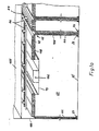
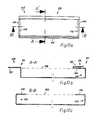
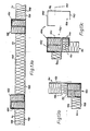
- FIG. 1a shows the arrangement of the building system 60 in a space delimited by a floor surface 35, a ceiling 105 and an outer wall 107.
- Floor surface 35 and ceiling 105 can, for. B. steel decks and the outer wall 107 may be a steel wall of a ship.
- the building system 60 consists of vertical wall elements 40, 41 which are connected to horizontal ceiling elements 48 by means of connecting profiles.
- ceiling supports 46 are provided, which can be fastened to the ceiling 105 by means of holding rails 47.
- the wall elements 40, 41 are supported on foot profiles 37, 38.
- the ceiling-side space is formed by the ceiling elements 48 and a panel end piece 73, which serves as a closure element for an assembled row of ceiling elements 48.
- the panel end piece can be provided with a lamp or air conditioning box 106. It is thus possible to integrate the raw installations for utilities in the building system, the installation of the lamp or air conditioning body only having to take place at the end of the assembly of the building system 60.
- the wall elements 40, 41 and ceiling elements 48 consist of metal sheeting 109 on the outside, between which an insulating layer 108 is arranged.
- the insulation layer can consist of glass wool, mineral wool or the like, or also of an insulation foam.
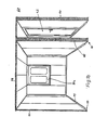
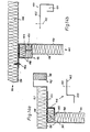
- FIG. 1b shows a further embodiment of rooms in which a window 97a is arranged in the outer wall 107 and a metal door 1, 2 is arranged in a side wall of the hallway.
- the ceiling elements 48 are self-supporting on the wall elements 40, 41.
- the foot profiles 37, 38 are covered with skirting boards 36 as in the embodiment according to FIG. 1a.
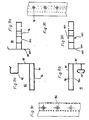
- the foot profile 37 intended for wall elements 41 is designed as a one-piece sheet metal blank with a U-shaped cross section (FIG. 2a).
- the side webs 112, 113 of this foot profile 37 serve as boundary webs for the wall element 41. It is possible to arrange the foot profile 37 directly on a floor surface 35 or to provide spacers or washers 56 between the floor surface 35 and the foot profile 37 for horizontal alignment.
- the side web 113 assigned to the metal cladding 109 is bent outwards on the end section side. This chamfered plate section serves as a spacer strip 55 and enables a small distance to the rear wall to be maintained at all times when mounting the foot profile 37 on a rear wall. This makes it possible to easily place cover profiles intended for ceiling storage on the upper end sections of the wall elements 41.
- the side web 112 assigned to the insulation layer 108 is oriented at an angle greater than 90 ° to the central web 114. This makes it easier to insert a wall element 41 into the foot profile 37.
- a foot profile 38 for a double-shell wall element 40 is shown in FIG. 2c.
- the foot profile 38 consists of two profile pieces 54 which are arranged at a distance from one another by means of a transition piece 50 and which are generally U-shaped in cross section.
- the transition piece 50 is formed by two strip elements 57 arranged at an angle to one another and connected to the profile pieces 54.
- the transition piece 50 maintains a distance between the profile pieces 54 such that a connection profile for holding ceiling elements 48 can be placed on the upper end sections of the individual wall elements 41 of the wall element 40.
- the inner side webs 53 of the profile pieces 54 are arranged at right angles to the base webs 52 and the outer side webs 51 to the base webs 52 at an angle greater than 90 °.
- the outer side webs 51 can be covered by means of baseboards 36 which are arranged on the respective floor covering of the floor surface 35.
- the foot profile 38 can also be aligned by means of washers 56 or the like on the bottom surface 35.
- the washers 56 are welded to the foot profile 38 as well as the foot profile 37 and connected to the bottom surface 35. If the floor surface 35 is designed as a steel ceiling, the foot profiles 37, 38 are also fastened to the washers 56 by welding. However, it is also possible to make the connection by means of adhesive or screw connections.
- a hat profile 65 is shown, which is used on the ceiling edge of the wall elements 40, 41 as a connection profile. It consists of a U-shaped profile section 66, on which a clamping profile 42 is formed for connecting ceiling elements 48. For the storage of ceiling elements 48 for smaller rooms, such as hallways and. Like.
- a ceiling support profile 67 can also be provided as a connection profile 64 on the ceiling-side edge of the wall elements 40, 41 (FIG. 3b).
- This ceiling support profile 67 consists of a U-shaped profile section 68 connected to the wall element 40, 41, on the one leg 69 of which a horizontal web 70 is arranged with a bevel 61 on the end section side. The ceiling elements 48 come to rest on this web 70.
- an insulating strip 71 is preferably made of a self-extinguishing material in the event of fire.
- webs 111, 112 with openings 113 can also be arranged in order to be able to fasten the connecting profiles 64 to ceiling beams 46 or holding rails 47.
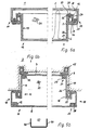
- a room wall with a metal door 1, 2 is shown schematically.
- the room wall consists of a wall element 40 formed from wall elements 41, on which in the area of the door opening 85 a door frame 9 by means of a wall connection profile 166 at the end sections of the wall element 40 is attached.
- the door 1, 2 bears against a sealing profile 15 which is inserted into a profile projection 91 of the door frame 9.
- a ceiling support profile 67 and / or a hat profile 65 is mounted on the wall connection profile 166, to which the respective ceiling elements 48 can be connected (FIG. 5a).
- the abutting edges between the wall connection profile 166 and the door frame 9 can be covered with a head profile 89.
- the head profile 89 can e.g. B. have a U-shaped cross-section, whereby a connection to the building system 60 is made possible by means of the side webs 90 (FIG. 5b).
- the door 1 according to Fig. 6a has a stiffening frame 3, which is bordered by the plate-shaped metal panels 5, 6.
- the stiffening frame 3 is designed as a circumferential profiled flat blank 10. It has a U-shaped core profile section 22, on the short leg 2415 of which a section 25 of the blank 10 is formed in a U-shape.
- the free web 28 of this section 25 abuts the metal paneling 5.
- a web 27 is formed at right angles, which abuts the metal paneling 6.
- the metal sheeting 5 is fastened to the inner web 29 of the section 25 by means of rivets 20.
- a flat section is likewise formed at right angles on the edge sections of the metal planking 6 and bears against the central web 30 of the core profile section 22 and is connected to the latter by means of rivets 20.
- the core profile section 22 and the edge section of the metal sheeting 6 form a groove 16 which serves to receive a sealing profile 14.
- the sealing profile 14 has an elastic molded web on the side, which covers the rivets 20 in the region of the inner web 29. The sealing profile 14 thus enables complete coverage of the rivets 20 of the rivet connections for fastening the metal cladding 5, 6 to the stiffening frame 3.
- the inner cavity of the door leaf 12 can be filled with a sound and fire-retardant insulating means 31.
- the door 2 shown in Fig. 6b is designed as a double rebate door. It also has a stiffening frame 4, on the edge sections of which the metal panels 7, 8 are fastened.
- the stiffening frame 4 is designed as a profiled flat blank 11 and has an approximately centrally arranged U-shaped core profile section 23.
- the fold connection 32 can be produced by rolling or the like.
- a U-shaped section 25 is formed on the short leg 24 of the core profile section 23, the free web 28 on the end section side thereof being connected to the metal paneling 8 by means of a rabbet connection 21.
- the core profile section 23 simultaneously forms the groove 16 for receiving a sealing profile 14.
- a further sealing profile 15 is fastened in a groove in the door frame 9.
- the door leaf 13 is sealed against the door frame 9 at two planar locations, so that with a sufficiently soundproof door and wall design, there is also adequate sound insulation in the area of the door frame.
- the inside of the door leaf 13 is filled with an insulating means 31, which expediently has fire and soundproofing properties.
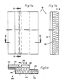
- FIG. 7 shows a window frame 97 which can be formed in a wall element 40, 41.
- the window frame 97 consists of two vertical connecting profiles 92, 93, and two horizontal curtain rails 98, 99 designed as a multi-chamber profile, which are connected to the surrounding wall elements 40, 41 by means of screw connections.
- the connection profiles 92, 93 each consist of a box-shaped frame 94 with a web 95 formed on one side, on which a clamping profile 42 or snap-in profile 43 is formed (FIGS. 8a to 8c).
- Grid-like openings 96, 96a are formed in the frame 94, which are used to pass screws for screw connections. It is also possible to attach special installation elements to these openings 96, 96a.
- a chamber 100 of the multi-chamber profile is provided with a longitudinal slot 101.
- This longitudinal slot 101 is used to connect the curtain to mounting rollers which are displaceably mounted in the chamber 100.
- a web-like locking stop 102 is formed on the multi-chamber profile as an installation aid.
- Cover webs 103 are formed on the multi-chamber profiles of the curtain rails 98, 99 and the connecting profiles 92, 93, into which the adjacent wall elements 40, 41 overlap.
- the edge sections 104 of the cover webs 103 are tapered in cross section (FIGS. 9a to 9c).
- FIGS. 10a to 10c A special design of a ceiling element is shown in FIGS. 10a to 10c.
- This ceiling element is designed as a ceiling panel 115 and consists of a rectangular sheet profile 128, which can be filled with an insulation layer 108.
- a U-shaped bend 118, 119 is formed on the transverse sides 116, 117 of the sheet metal profile 128, which serves for the lateral transverse reinforcement of the sheet metal profile 128 and for fixing the insulation layer 108 in position.
- An L-shaped profile edge 122, 124 is formed on each of the long sides 120, 121. These profile edges 122, 124 serve once for the longitudinal stiffening of the sheet metal profile 128 and for fixing the position of an insulation layer 108, and also as connecting elements for connecting a plurality of ceiling panels 115
- the profile edge 124 is designed as a clamping member 126, for which purpose a clamping web 125 is bent outwards on the inside end section of the end web 127.
- the end web 123 of the one ceiling panel 115 is inserted into the clamping member 126 formed by the clamping web 125 and the end web 127 of the preceding ceiling panel 115. In this way, a sufficient fixation of the position of the ceiling panels is achieved, the transverse sides 116, 117 of which rest on webs 70 of connection profiles.
- the last two ceiling panels 115 are stacked one above the other, inserted into the ceiling openings, whereupon the last ceiling panel 115 can be pulled down to close the remaining opening.
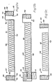
- 11a to 16d show components for the building system 60, which have sufficient rigidity even at greater heights of approximately 4.50 m and larger unsupported spans of z. B. 3 m allows. If the spans of the ceiling elements are to be increased still further, it is necessary to intercept the ceiling elements on ceiling beams 46 or the like.
- the ceiling element 48 shown in FIGS. 11a to 11c consists of a metal sheeting 174 with edge profiles 177, 178 formed on the edge sections 175, 176, each with projecting support webs 183, 184, which are stiffened by internal folds 185, 186.
- the cavity 187 formed by the edge profiles 177, 178 can be filled with an insulation layer 108.
- the support webs 183, 184 are of different lengths, so that on-site tolerances can be compensated for by shifting the support webs 183, 184 of abutting ceiling elements 48 in the region of the joint 181.
- the support webs 183, 184 lie one on top of the other and one edge profile 177 of one ceiling element 48 overlaps the other edge profile 178 of the other ceiling element 48 (FIG. 11d).
- the ceiling elements 48 can also be fastened to angle pieces 173 which are arranged in the region of the ceiling edge on the wall elements 40, 41 (FIGS. 11e and 11f).
- the web 180 which is upturned on the end section side on the holding web 179 of each angle piece 173, enables a shell-shaped design of the holding web 179 into which an insulating strip 182 made of foam rubber or the like can be inserted.
- the angle pieces 173 are fastened to the wall elements 40, 41 by means of screw connections 156.
- the clamping profile 131 consists of a generally U-shaped profile blank, the one elongated web 133 of which is arranged at right angles on the plate element 130 of the wall element 41 and is connected to the latter.
- the end web 135 of the clamping profile 131 is arranged at right angles to the central web 134, parallel to the elongated web 133, and is aligned with the plate element 130 of the metal plating 109.
- the snap-in profile 132 consists of an enlarged U-shaped profile piece 137, one web of which is designed as a holding web 136 and is connected at right angles to the plate element 130.
- the holding web 136 is arranged parallel to the elongated web 133 and in the same direction as this.
- an angle web 139 is formed, the end web portion 140 of which is aligned parallel to the holding web 136 and projects into the profile piece 137.
- An insulation means 108 can be embedded in the cavity formed by the angular web 139 of the snap-in profile 132 and the clamping profile 131.
- an insulating means 108 can be arranged on the plate element 130, wherein a plate section with insulating means 108 remains unfilled on the area facing the clamping profile 131, so that the angular web 139 of the profile piece 137 of the adjacent wall element 41 can be inserted into this area.
- 12b and 12c show two wall elements 41 designed as end pieces 44, 45.
- a snap-in profile 132 and a clamping web 49 are each formed at the end section.
- B. at corner connections in a snap profile 132 of an adjacent wall element 41 can be inserted.
- the end piece 45 has a clamping profile 131 at the edge-side end sections.
- FIGS. 13a and 13b by simply pushing the clamping profile 131 and the snap-in profile 132 into one another, two adjacent wall elements 41 can be connected both in a longitudinal direction and to form an outer corner. If the clamping effect between the clamping profile 131 and the snap-in profile 132 is not sufficient for sufficient rigidity of the wall construction, it is possible to additionally provide, for example, rivet connections by means of blind rivets or the like. Cavities in the area of the connecting sections are expediently filled with an insulating agent 108.
- FIG. 13c shows an inside corner connection, in which the connection of the clamping profile 131 and the snap-in profile 132 of two adjacent wall elements 41 takes place by means of a corner profile piece 143.
- the corner profile piece 143 consists of a U-shaped base profile 145, one side leg 146 of which is elongated and has a retaining web 147 to form a clamping section 144 at the end section.
- the clamping profile 131 and the snap-in profile 132 are then held at an inner corner 142 between the base profile 145 and the holding web 147.
- this may be connected by means of rivet or screw with the snap p rofile or 132 but also with the clamping profile 131st For this Openings 153 may already be provided in the side leg 146 before the corner profile piece 143 is installed.
- a tolerance compensation piece 148 or 154 can be used to secure it.
- the tolerance compensation piece 148 is Z-shaped in cross section and consists of a holding leg 152 which on the plate element 130 of a wall element 41 z. B. can be fastened by means of rivet connections 151.
- An angle piece 150 is formed on the holding leg 152 and forms an opening section 149. The clamping profile 131 of the wall element 41 to be fastened can be pushed into this opening section 149 (FIG. 14a).
- This tolerance compensation piece 154 has a holding leg 155, on one end section of which a clamping profile 131 is formed at right angles.
- the tolerance compensation piece 154 is connected to the plate element 130 of the one wall element 41 by means of screw connections 156. It is also possible to provide 156 rivet connections instead of the screw connections.
- the other wall element 41 is fastened by laterally inserting the snap-in profile 132 via the clamping profile 131 of the tolerance compensation piece 154 (FIG. 14b).
- the door frame 9 consists of two frame connection profiles 157, 158, at the end sections 159, 160; 161, 162 alternately a snap-in profile 132 or clamping profile 131 is formed. Then either additional profile pieces as connecting elements or else further wall elements 41 can be connected directly to the clamping profiles 131 or snap-in profiles 132.
- the door frame 9a consists of two frame connection profiles 163, 164, each of which consists of a door stop profile 165 with mutually molded clamping profile 131 or snap profile 132 and a wall connection profile 166 with also mutually molded snap profile 132 or clip profile 131.
- the frame connection profiles 163, 164 are connected to the door stop profiles 165 by means of rivet connections 151 or screw connections 156.
- FIG. 16 shows the connection of a partition 169 to a wall element 41 between its clamping profile 131 and snap-in profile 132.
- a connecting piece 171 is provided which consists of a basic profile with a Z-shaped cross section, at one end section of which an angle section 150 is formed to form an opening section 149, and at the other end section thereof Clamping profile 131 is formed.
- This clamping profile 131 is pushed into the snap-in profile 132 of the one wall element 41 of the partition 169.
- the clamping profile 131 of the other wall element 41 of the partition 169 is inserted into the opening section 149.
- the connection to the plate element 130 of the first wall element 41 takes place by means of screw connections 156, the screws being guided through the end section of the angle piece 150 and the clamping profile 131 of the one wall element 410 of the partition wall 169.
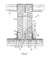
- FIG. 17 shows a partition 74 through which a wet room 76 is separated from a drying room 75.
- the drying chamber-side wall element 41 is mounted on foot profiles 37.
- the spacer strip 55 lies against a support wall 77 fastened on the base surface 35, on which a spacer profile piece 78 is mounted.
- an upper U-shaped holding profile 79 is formed on the spacer 78, which is pushed over the spacer 78.
- the wall element 41 on the wet room side is mounted on a lower holding profile 80, the metal cladding 109 being able to be associated with the spacer profile piece 78.
- An insulating layer 81 is arranged between the holding profile 80 and the wall element 41 on the wet room side.
- a substructure 82 adjoins the holding profile 80 and the lower region of the wall element 41 on the wet room side, which may consist either of a molding compound or of a molding profile body.
- the substructure 82 and the surface 83 on the wet side of the wall element 41 on the wet side can be covered with tiles 84 or else coated with a water-repellent composition.
Description
- Die Erfindung betrifft ein Bausystem zur Auskleidung und Aufteilung eines mindestens eine Deckenfläche und eine Bodenfläche aufweisenden Raumes mit Wänden und/oder Decken aus plattenförmigen Elementen, die mit an der Deckenfläche und Bodenfläche angeordneten, als Profilstück ausgebildeten Trägern verbunden sind und deren Seitenkanten Klemmprofile aufweisen, die zur Versteifung der Wand oder Decke mit Klemmprofilen des benachbarten plattenförmigen Elements verbindbar sind.
- Ein derartiges Bausystem ist bereits durch die DE-AS 19 37 443 und die DE-OS 23 40 909 bekannt geworden. Dieses bekannte System hat jedoch den Nachteil, daß bei zweischaligen Wänden die Träger nur schwierig herzustellen und die Klemmprofile bei größeren Bauhöhen der Platte oder bei der Aufstellung in Erschütterungen ausgesetzten Räumen keinen sicheren Halt vermitteln.
- Die Aufgabe der Erfindung besteht darin, ein gattungsgemäßes Bausystem zu schaffen, das in Anpassung an die jeweiligen Beanspruchungen eine einfache Montage auch zweischaliger Wände ermöglicht und es gestattet, Raumaufteilungen einfach und billig durchzuführen.
- Erfindungsgemäß erfolgt die Lösung der Aufgabe durch die Kombination folgender Merkmale :
- a) jedes Wandelementelement ist in an sich bekannter Weise auf einem aus einem oder mehreren Profilstücken ausgebildeten trägerartigen Fußprofil abgestützt, das auf der Bodenfläche horizontal ausgerichtet mit dieser mittels Haltemitteln fest verbunden ist,
- b) an der einen langen Seitenkante eines jeden Wandelements ist ein einseitig mit diesem verbundenes allgemein U-förmiges Klemmprofil mit zwei Seitenstegen und einem Mittelsteg ausgebildet, bei dem rechtwinklig zur Plattenebene ein verlängerter Seitensteg des U-förmigen Klemmprofils mit zur Plattenebene gerichtetem Öffnungsabschnitt derart angeordnet ist, daß das Klemmprofil in ein an der anderen langen Seitenkante des zu verbindenden Wandelements ausgebildetes Einrastprofil einklemmbar ist, das aus einem parallel zum verlängerten Seitensteg des Klemmprofils angeordneten Haltesteg eines großen U-förmigen Profilstücks besteht, an dessen freiem, dem Haltesteg gegenüberliegenden Seitensteg endabschnittsseitig zum Haltesteg ausgerichtet ein Winkelsteg derart angeformt ist, daß dessen endseitiger Stegabschnitt parallel zum Haltesteg ausgerichtet ist und von diesem in einem der Länge des Mittelstegs des Klemmprofils entsprechenden Abstand angeordnet ist,
- c) an den deckenseitigen Begrenzungskanten der Wandelemente sind mit den Deckenträgern verbindbare Anschlußprofile zur Halterung der Deckenelemente angeordnet.
- Weitere vorteilhafte Ausgestaltungen der Erfindung werden in den Unteransprüchen beschrieben. Ein Ausführungsbeispiel der Erfindung mit verschiedenen Ausgestaltungen ist in den Zeichnungen dargestellt. Es zeigt
- Figuren 1a und 1b das erfindungsgemäße Bausystem in schaubildlichen Ansichten im Ausschnitt,
- Figuren 2a und 2c ein Fußprofil für ein einschaliges Wandelement in der Seitenansicht im Schnitt,
- Figur 2c ein Fußprofil für ein zweischaliges Wandelement in der Seitenansicht im Schnitt,
- Figur 3a ein als Doppelhutprofil ausgebildetes Anschlußprofil in der Seitenansicht,
- Figur 3b ein weiteres Anschlußprofil in der Seitenansicht
- Figur 4 einen Türdurchbruch in einer schematischen Ansicht von oben,
- Figur 5a den deckenseitigen Anschluß der Türzarge an die Deckenelemente in einer Seitenansicht im Schnitt,
- Figur 5b ein Kopfprofil für den Türdurchbruch in einer Seitenansicht,
- Figuren 6a und 6b zwei Türen für einen Türdurchbruch in der Draufsicht im Schnitt,
- Figur 7 einen Fensterrahmen in einer Ansicht von oben,
- Figuren 8a und 8b zwei Anschlußprofile des Fensterrahmens in der Draufsicht,
- Figur 8c ein Anschlußprofil im Ausschnitt in der Ansicht von vorn,
- Figuren 9a und 9b zwei Gardinenschienen in der Seitenansicht im Schnitt,
- Figur 9c eine Gardinenschiene im Ausschnitt in der Ansicht von vorn,
- Figuren 10a bis 10c ein Deckenpaneel in einer Ansicht von oben und einer Quer- und Längsansicht im Schnitt
- Figuren 11a bis 11c ein Deckenelement in einer Ansicht von vorn, in einer Seitenansicht und einer Queransicht,
- Figur 11d die Anordnung von Deckenelementen in der Queransicht
- Figuren 11e und 11f die Haiterung von Deckenelementen in der Queransicht
- Figuren 12a bis 12c die Ausbildung von Wandelementen in einer Draufsicht
- Figuren 13a und 13b eine Längs- und Eckverbindung von zwei Wandelementen nach Fig. 12a und 12b in der Draufsicht,
- Figur 13c eine Außeneckverbindung von zwei Wandelementen in der Draufsicht
- Figur 13d eine weitere Ausbildung einer Eckverbindung in der Draufsicht
- Figur 14a einen Wandelementanschluß mit einem Toleranzausgleichstück in der Draufsicht
- Figur 14b eine weitere Ausbildung eines Wandelementanschlusses mit einem Toleranzausgleichstück in der Draufsicht
- Figuren 15a und 15b die Ausbildung von Türzargen in der Draufsicht
- Figur 16 einen Trennwandanschluß in der Draufsicht
- Figur 17 eine Trennwandanordnung zwischen einem Trockenraum und einem Naßraum in einer schematischen Seitenansicht im Schnitt.
- In Fig. 1a ist die Anordnung des Bausystems 60 in einem durch eine Bodenfläche 35, eine Decke 105 sowie eine Außenwand 107 begrenzten Raum dargestellt. Bodenfläche 35 und Decke 105 können z. B. Stahldecks und die Außenwand 107 eine Stahlwand eines Schiffes sein. Das Bausystem 60 besteht aus vertikalen Wandelementen 40, 41, die mittels Anschlußprofilen mit horizontalen Deckenelementen 48 verbunden sind. Zur Halterung der Deckenelemente 48 sind Deckenträger 46 vorgesehen, die mittels Halteschienen 47 an der Decke 105 befestigbar sind. Bodenseitig sind die Wandelemente 40, 41 auf Fußprofilen 37, 38 abgestützt. Die deckenseitige Raumausbildung erfolgt durch die Deckenelemente 48 sowie ein Paneelendstück 73, das als Verschlußelement für eine montierte Reihe von Deckenelementen 48 dient. Das Paneelendstück kann mit einem Lampen- oder Klimatisierungskasten 106 versehen sein. Es ist somit möglich, die Rohinstallationen für Versorgungseinrichtungen in das Bausystem zu integrieren, wobei der Einbau der Lampen- oder Klimatisierungskörper erst am Ende der Montage des Bausystems 60 erfolgen muß. Die Wandelemente 40, 41 und Deckenelemente 48 bestehen aus außenseitigen Metallbeplankungen 109, zwischen denen eine Dämmschicht 108 angeordnet ist. Die Dämmschicht kann aus Glaswolle, Mineralwolle od. dgl. oder aber auch aus einem Dämmschaum bestehen.
- Fig. 1 b zeigt eine weitere Ausbildung von Räumen, bei der in der Außenwand 107 ein Fenster 97a und in einer Seitenwand des Flurs eine Metalltür 1, 2 angeordnet ist. Bei dieser Ausführungsform sind die Deckenelemente 48 selbsttragend auf den Wandelementen 40, 41 gelagert. Die Fußprofile 37, 38 sind wie bei der Ausbildung nach Fig. 1a mit Sockelleisten 36 abgedeckt.
- Das für Wandelemente 41 bestimmte Fußprofil 37 ist als einstückiger Blechzuschnitt mit U-förmigem Querschnitt ausgebildet (Fig. 2a). Die Seitenstege 112, 113 dieses Fußprofils 37 dienen als Begrenzungsstege für das Wandelement 41. Es ist möglich, das Fußprofil 37 direkt auf einer Bodenfläche 35 anzuordnen oder aber zwischen der Bodenfläche 35 und dem Fußprofil 37 zur horizontalen Ausrichtung Distanzstücke oder Unterlegplatten 56 vorzusehen. Der der Metallbeplankung 109 zugeordnete Seitensteg 113 ist endabschnittsseitig nach außen abgekantet. Dieser abgekantete Plattenabschnitt dient als Distanzstreifen 55 und ermöglicht es, daß bei Montage des Fußprofils 37 an einer Rückwand stets ein geringer Abstand zur Rückwand gewahrt bleibt. Hierdurch ist es möglich, leicht für die Deckenlagerung bestimmte Abdeckprofile auf die oberen Endabschnitte der Wandelemente 41 aufzusetzen. Der der Dämmschicht 108 zugeordnete Seitensteg 112 ist zum Mittelsteg 114 in einem Winkel größer als 90° ausgerichtet. Hierdurch wird das Einschieben eines Wandelements 41 in das Fußprofil 37 erleichtert.
- In Fig. 2c ist ein Fußprofil 38 für ein zweischaliges Wandelement 40 dargestellt. Das Fußprofil 38 besteht aus zwei mittels eines Übergangsstücks 50 im Abstand voneinander angeordneten Profilstücken 54, die im Querschnitt allgemein U-förmig ausgebildet sind. Das Übergangsstück 50 ist durch zwei miteinander und mit den Profilstücken 54 verbundene im Winkel zueinander angeordnete Streifenelemente 57 gebildet. Durch das Übergangsstück 50 wird zwischen den Profilstücken 54 ein derartiger Abstand gewahrt, daß an den oberen Endabschnitten der einzelnen Wandelemente 41 des Wandelements 40 jeweils ein Anschlußprofil zur Halterung von Deckenelementen 48 aufgesetzt werden kann. Die inneren Seitenstege 53 der Profilstücke 54 sind zu den Bodenstegen 52 rechtwinklig und die äußeren Seitenstege 51 zu den Bodenstegen 52 in einem Winkel größer als 90° angeordnet. Hierdurch wird wie bei dem Fußprofil 37 das Einschieben der einzelnen Wandelemente 41 zur Ausbildung des Wandelements 40 erleichtert. Die Abdeckung der äußeren Seitenstege 51 kann mittels Sockelleisten 36 erfolgen, die auf dem jeweiligen Bodenbelag der Bodenfläche 35 angeordnet werden. Das Fußprofil 38 kann ebenfalls mittels Unterlegplatten 56 od. dgl. auf der Bodenfläche 35 ausgerichtet werden. Die Unterlegplatten 56 werden wie beim Fußprofil 37 auch mit dem Fußprofil 38 verschweißt sowie mit der Bodenfläche 35 verbunden. Sofern die Bodenfläche 35 als Stahldecke ausgebildet ist, erfolgt die Befestigung der Fußprofile 37, 38 mit den Unterlegplatten 56 ebenfalls durch Schweißung. Es ist aber auch möglich, die Verbindung durch Kleb- oder Schraubverbindungen herzustellen.
- In Fig. 3a ist ein Hutprofil 65 dargestellt, das an der deckenseitigen Kante der Wandelemente 40, 41 als Anschlußprofil verwendet wird. Es besteht aus einem U-förmigen Profilabschnitt 66, an dem ein Klemmprofil 42 zum Anschluß von Deckenelementen 48 angeformt ist. Für die Lagerung von Deckenelementen 48 für kleinere Räume, wie Flure u. dgl. kann an der deckenseitigen Kante der Wandelemente 40, 41 als Anschlußprofil 64 auch ein Deckenhalteprofil 67 vorgesehen werden (Fig. 3b). Dieses Deckenhalteprofil 67 besteht aus einem U-förmigen mit dem Wandelement 40, 41 verbundenen Profilabschnitt 68, an dessen einem Schenkel 69 ein horizontaler Steg 70 mit einer endabschnittsseitigen Aufkantung 61 angeordnet ist. Auf diesen Steg 70 kommen die Deckenelemente 48 zur Auflage. Zwischen dem Steg 70 und den Deckenelementen 48 wird vorzugsweise eine Dämmstreifen 71 aus einem bei Feuer selbstlöschendem Werkstoff angeordnet. An dem Profilabschnitt 68 können auch Stege 111, 112, mit Durchbrechungen 113 angeordnet sein, um die Anschlußprofile 64 an Deckenträgern 46 oder Halteschienen 47 befestigen zu können.
- In Fig. 4 ist eine Raumwand mit einer Metalltür 1, 2 schematisch dargestellt. Die Raumwand besteht aus einem aus Wandelementen 41 gebildeten Wandelement 40, an dem im Bereich des Türdurchbruchs 85 eine Türzarge 9 mittels eines Wandanschlußprofils 166 an den Endabschnitten des Wandelements 40 befestigt ist. Die Tür 1, 2 liegt im geschlossenen Zustand an einem Dichtungsprofil 15 an, das in einen Profilvorsprung 91 der Türzarge 9 eingesetzt ist.
- Bei raumhohen Türdurchbrüchen 85 wird an dem Wandanschlußprofil 166 ein Deckenhalteprofil 67 und/oder ein Hutprofil 65 gelagert, an dem die jeweiligen Deckenelemente 48 angeschlossen werden können (Fig.5a). Soweit erforderlich, können die Stoßkanten zwischen dem Wandanschlußprofil 166 und der Türzarge 9 mit einem Kopfprofil 89 abgedeckt werden. Das Kopfprofil 89 kann z. B. einem U-förmigen Querschnitt aufweisen, wobei mittels der Seitenstege 90 eine Verbindung mit dem Bausystem 60 ermöglicht wird (Fig. 5b).
- In den Fig.6a und 6b sind zwei Ausführungsformen von Türen 1, 2 dargestellt, die jeweils als Metalltür ausgebildet sind. Die Tür 1 nach Fig. 6a weist einen Versteifungsrahmen 3 auf, der von den plattenförmigen Metallbeplankungen 5, 6 eingefaßt ist. Der Versteifungsrahmen 3 ist als umlaufender profilierter flächiger Zuschnitt 10 ausgebildet. Er weist einen U-förmigen Kernprofilabschnitt 22 auf, an dessen einem kurzen Schenkel 2415 ein Abschnitt 25 des Zuschnitts 10 U-förmig angeformt ist. Der freie Steg 28 dieses Abschnitts 25 liegt an der Metallbeplankung 5 an. An dem freien Endabschnitt des langen Schenkels des Kernprofilabschnitts 22 ist rechtwinklig ein Steg 27 angeformt, der an der Metallbeplankung 6 anliegt. Die Metallbeplankung 5 ist an dem inneren Steg 29 des Abschnitts 25 mittels Nieten 20 befestigt. An den Randabschnitten der Metallbeplankungen 6 ist ebenfalls rechtwinklig ein flächiger Abschnitt ausgebildet, der an dem Mittelsteg 30 des Kernprofilabschnitts 22 anliegt und mit diesem mittels Nieten 20 verbunden ist. Der Kernprofilabschnitt 22 und der Randabschnitt der Metallbeplankung 6 bilden eine Nut 16, die zur Aufnahme eines Dichtungsprofils 14 dient. Das Dichtungsprofil 14 weist seitlich einen elastischen angeformten Steg auf, der die Nieten 20 im Bereich des inneren Steges 29 abdeckt. Das Dichtungsprofil 14 ermöglicht somit eine vollständige Abdeckung der Nieten 20 der Nietverbindungen zur Befestigung der Metallbeplankungen 5, 6 an dem Versteifungsrahmen 3. Der innere Hohlraum des Türblatts 12 kann mit einem schall- und feuerhemmenden Dämmittel 31 verfüllt sein.
- Die in Fig. 6b dargestellte Tür 2 ist als Doppelfalztür ausgebildet. Sie weist ebenfalls einen Versteifungsrahmen 4 auf, an dessen Randabschnitten die Metallbeplankungen 7, 8 befestigt sind. Der Versteifungsrahmen 4 ist als profilierter flächiger Zuschnitt 11 ausgebildet und weist einen etwa mittig angeordneten U-förmigen Kernprofilabschnitt 23 auf. An dem langen Steg 26 des Kernprofilabschnits 23 ist endabschnittseitig ein Steg 27 rechtwinklig angeformt, an den mittels einer Falzverbindung die Endabschnitte der Metallbeplankung 7 befestigt sind. Die Falzverbindung 32 kann durch Rollen od. dgl. hergestellt sein. An dem kurzen Schenkel 24 des Kernprofilabschnitts 23 ist ein U-förmiger Abschnitt 25 angeformt, dessen endabschnittseitiger freier Steg 28 mittels einer Falzverbindung 21 mit der Metallbeplankung 8 verbunden ist. Der Kernprofilabschnitt 23 bildet gleichzeitig die Nut 16 zur Aufnahme eines Dichtungsprofils 14. Ein weiteres Dichtungsprofil 15 ist in einer Nut der Türzage 9 befestigt. Hierdurch erfolgt die Abdichtung des Türblattes 13 gegen die Türzarge 9 an zwei flächigen Stellen, so daß bei einer ausreichend schalldichten Tür- und Wandausbildung auch im Bereich der Türzarge ein ausreichender Schallschutz vorliegt. Das Türblatt 13 ist innenseitig mit einem Dämmittel 31 verfüllt, das zweckmäßigerweise feuer- und schallhemmende Eigenschaften aufweist.
- In Fig. 7 ist ein Fensterrahmen 97 dargestellt, der in einem Wandelement 40, 41 ausgebildet werden kann. Der Fensterrahmen 97 besteht aus zwei vertikalen Anschlußprofilen 92, 93, und zwei horizontalen als Mehrkammerprofil ausgebildeten Gardinenschienen 98, 99, die mittels Schraubverbindungen mit den umgebenden Wandelementen 40, 41 verbunden sind. Die Anschlußprofile 92, 93 bestehen jeweils aus einem kastenförmigen Rahmen 94 mit einem einseitig angeformten Steg 95, an dem ein Klemmprofil 42 oder Einrastprofil 43 ausgebildet ist (Fig. 8a bis 8c). In dem Rahmen 94 sind rasterartige Durchbrechungen 96, 96a ausgebildet, die zum Durchführen von Schrauben für Schraubverbindungen dienen. Es ist auch möglich, an diesen Durchbrechungen 96, 96a besondere Einbauelemente zu befestigen. In den Profilen der Gardinenschienen 98, 99 ist eine Kammer 100 des Mehrkammerprofils mit einem Längsschlitz 101 versehen. Dieser Längsschlitz 101 dient zur Verbindung der Gardine mit in der Kammer 100 verschieblich gelagerten Befestigungsrollen. Als Einbauhilfe ist an dem Mehrkammerprofil ein stegartiger Arretierungsanschlag 102 ausgebildet. An den Mehrkammerprofilen der Gardinenschienen 98, 99 und den Anschlußprofilen 92, 93 sind Abdeckstege 103 angeformt, in die die angrenzenden Wandelemente 40, 41 übergreifen. Zur Verringerung der Geräuschbildung sind die Randabschnitte 104 der Abdeckstege 103 im Querschnitt sich verjüngend ausgebildet (Fig.9a bis 9c).
- Eine besondere Ausbildung eines Deckenelements ist in Fig. 10a bis 10c dargestellt. Dieses Deckenelement ist als Deckenpaneel 115 ausgebildet und besteht aus einem rechteckigem Blechprofil 128, das mit einer Dämmschicht 108 ausgefüllt sein kann. An den Querseiten 116, 117 des Blechprofils 128 ist jeweils eine U-förmige Abkantung 118, 119 ausgebildet, die zur seitlichen Querversteifung des Blechprofils 128 sowie zur Lagefixierung der Dämmschicht 108 dient. An den Längsseiten 120, 121 ist jeweils eine L-förmige Profilkante 122, 124 ausgebildet. Diese Profilkanten 122,124 dienen einmal zur Längsversteifung des Blechprofils 128 und zur Lagefixierung einer Dämmschicht 108 wie auch als Verbindungselemente zur Verbindung mehrerer Deckenpaneele 115. Hierzu weist die Profilkante
- 122 einen freien, nach außen gerichteten Endsteg 123 auf. Die Profilkante 124 ist als Klemmglied 126 ausgebildet, wozu an dem innenseitigen Endabschnitt des Endstegs 127 ein Klemmsteg 125 nach außen abgekantet ist. Beim Zusammenbau von mehreren Deckenpaneelen 115 zu einer Decke wird der Endsteg 123 des einen Deckenpaneels 115 in das durch den Klemmsteg 125 und den Endsteg 127 des vorgehenden Deckenpaneels 115 gebildete Klemmglied 126 eingeschoben. Hierdurch wird eine ausreichende Lagefixierung der Deckenpaneele erzielt, die mit ihren Querseiten 116, 117 auf Stegen 70 von Anschlußprofilen aufliegen. Zur Montage des jeweils letzten Deckenpaneels 115 einer Decke werden die letzten beiden Deckenpaneele 115 übereinander gestapelt, in die Deckenöffnungen eingesetzt, worauf dann das letzte Deckenpaneel 115 zum Verschließen der Restöffnung herabgezogen werden kann.
- In den Fig. 11a bis 16d sind Bauelemente für das Bausystem 60 dargestellt, das eine ausreichende Steifigkeit auch bei größeren Höhen von ca. 4,50 m und größeren freitragenden Spannweiten von z. B. 3 m ermöglicht. Sollen die Spannweiten der Deckenelemente noch weiter vergrößert werden, ist es erforderlich, die Deckenelemente an Deckenträgern 46 od. dgl. abzufangen.
- Das in den Fig. 11a bis 11c dargestellte Deckenelement 48 besteht aus einer Metallbeplankung 174 mit an den Randabschnitten 175, 176 ausgebildeten Randprofilen 177, 178 mit jeweils vorragenden Auflagerstegen 183, 184, die durch innere Abkantungen 185, 186 versteift sind. Der durch die Randprofile 177, 178 gebildete Hohlraum 187 kann mit einer Dämmschicht 108 verfüllt sein. Die Auflagerstege 183, 184 sind unterschiedlich lang ausgebildet, so daß bauseitige Toleranzen durch verschieben der Auflagerstege 183, 184 jeweils aneinanderstoßender Deckenelemente 48 im Bereich der Fuge 181 ausgeglichen werden können. Die Auflagerstege 183, 184 liegen dabei aufeinander und das eine Randprofil 177 des einen Deckenelements 48 überlappt das andere Randprofil 178 des anderen Deckenelements 48 (Fig. 11d).
- Die Deckenelemente 48 können außer auf Anschlußprofilen 64 (Fig. 3b) auch auf Winkelstücken 173 befestigt werden, die im Bereich des Deckenrandes an den Wandelementen 40, 41 angeordnet werden (Fig. 11e und 11f). Der endabschnittseitig an dem Haltesteg 179 eines jeden Winkelstücks 173 aufgekantete Steg 180 ermöglicht eine schalenförmige Ausbildung des Haltestegs 179, in die ein Dämmstreifen 182 aus Moosgummi od. dgl. eingelegt werden kann. Die Befestigung der Winkelstücke 173 an den Wandelementen 40, 41 erfolgt mittels Schraubverbindungen 156.
- In Fig. 12a ist in einer Draufsicht ein Wandelement 41 dargestellt, an dessen randseitigen Endabschnitten ein Klemmprofil 131 und ein Einrastprofil 132 ausgebildet ist. Das Klemmprofil 131 besteht aus einem allgemein U-förmigen Profilzuschnitt, dessen einer verlängerter Steg 133 rechtwinklig an dem Plattenelement 130 des Wandelements 41 angeordnet und mit diesem verbunden ist. Der Endsteg 135 des Klemmprofils 131 ist rechtwinklig zum Mittelsteg 134 parallel zu dem verlängerten Steg 133 angeordnet und zu dem Plattenelement 130 der Metallbeplankung 109 ausgerichtet. Das Einrastprofil 132 besteht aus einem vergrößerten U-förmigen Profilstück 137, dessen einer Steg als Haltesteg 136 ausgebildet und rechtwinklig mit dem Plattenelement 130 verbunden ist. Der Haltesteg 136 ist parallel zum verlängerten Steg 133 und in gleicher Richtung wie dieser angeordnet. An dem endseitigen Seitensteg 138 des Profilstücks 137 ist ein Winkelsteg 139 angeformt, dessen endseitiger Stegabschnitt 140 parallel zum Haltesteg 136 ausgerichtet ist und in das Profilstück 137 ragt. In dem durch den Winkelsteg 139 des Einrastprofils 132 und das Klemmprofil 131 gebildeten Hohlraum kann ein Dämmittel 108 eingelagert werden. Ebenso kann auf dem Plattenelement 130 ein Dämmittel 108 angeordnet werden, wobei an dem dem Klemmprofil 131 zugewandten Bereich ein Plattenabschnitt mit Dämmittel 108 unverfüllt bleibt, damit in diesen Bereich der Winkelsteg 139 des Profilstücks 137 des benachbarten Wandelements 41 eingeführt werden kann.
- In den Fig. 12b und 12c sind zwei als Endstücke 44, 45 ausgebildete Wandelemente 41 dargestellt. An dem Endstück 44 ist endabschnittseitig je ein Einrastprofil 132 und ein Klemmsteg 49 ausgebildet, der z. B. bei Eckverbindungen in ein Einrastprofil 132 eines angrenzenden Wandelements 41 eingeschoben werden kann. Das Endstück 45 weist an den randseitigen Endabschnitten jeweils ein Klemmprofil 131 auf.
- Wie in den Fig. 13a und 13b dargestellt, können durch einfaches Ineinanderschieben des Klemmprofils 131 und des Einrastprofils 132 zweier benachbarter Wandelemente 41 diese sowohl in einer Längsrichtung wie auch zu einer Außenecke verbunden werden. Sofern die Klemmwirkung zwischen Klemmprofil 131 und Einrastprofil 132 für eine ausreichende Steifigkeit der Wandkonstruktion nicht ausreicht, ist es möglich, zusätzlich beispielsweise Nietverbindungen mittels Blindnieten od. dgl. vorzusehen. Hohlräume im Bereich der Verbindungsabschnitte werden zweckmäßigerweise mit einem Dämmittel 108 verfüllt.
- In Fig. 13c ist eine innenseitige Eckverbindung dargestellt, bei der die Verbindung von Klemmprofil 131 und Einrastprofil 132 zweier benachbarter Wandelemente 41 mittels eines Eckprofilstücks 143 erfolgt. Das Eckprofilstück 143 besteht aus einem U-förmigen Grundprofil 145, dessen einer Seitenschenkel 146 verlängert ausgebildet ist und zur Ausbildung eines Klemmabschnitts 144 endabschnittseitig einen Haltesteg 147 aufweist. Zwischen dem Grundprofil 145 und dem Haltesteg 147 sind bei einer Innenecke 142 dann das Klemmprofil 131 und das Einrastprofil 132 gehalten. Um das Eckprofilstück 143 festzulegen, kann dieses mit dem Einrastprofil 132 oder aber auch mit dem Klemmprofil 131 mittels Niet- oder Schraubverbindungen verbunden sein. Hierzu können vor der Montage des Eckprofilstücks 143 in dem Seitenschenkel 146 bereits Durchbrechungen 153 vorgesehen sein.
- Sofern senkrecht zu einem Wandelement 41 zwischen dessen endseitig angeordnetem Klemmprofil 131 und Einrastprofil 132 senkrecht zur Ebene des Wandelements 41 ein weiteres Wandelement 41 angeordnet werden soll, kann zu dessen Befestigung ein Toleranzausgleichstück 148 bzw. 154 verwendet werden. Das Toleranzausgleichstück 148 ist im Querschnitt Z-förmig ausgebildet und besteht aus einem Halteschenkel 152, der an dem Plattenelement 130 des einen Wandelements 41 z. B. mittels Nietverbindungen 151 befestigt werden kann. An dem Halteschenkel 152 ist ein Winkelstück 150 angeformt, das einen Öffnungsabschnitt 149 bildet. In diesen Öffnungsabschnitt 149 kann das Klemmprofil 131 des zu befestigenden Wandelements 41 eingeschoben werden (Fig. 14a). Sofern das Einrastprofil 132 eines Wandelements 41 an einem anderen Wandelement 41 befestigt werden soll, ist es erforderlich, das Toleranzausgleichstück 154 vorzusehen. Dieses Toleranzausgleichstück 154 weist einen Halteschenkel 155 auf, an dessen einem Endabschnitt rechtwinklig ein Klemmprofil 131 angeformt ist. Das Toleranzausgleichstück 154 ist mittels Schraubverbindungen 156 mit dem Plattenelement 130 des einen Wandelements 41 verbunden. Es ist auch möglich, statt der Schraubverbindungen 156 Nietverbindungen vorzusehen. Die Befestigung des anderen Wandelements 41 erfolgt durch seitliches Einschieben des Einrastprofils 132 über das Klemmprofil 131 des Toleranzausgleichstücks 154 (Fig. 14b).
- In den Fig. 15a und 15b sind zwei Türzargen 9, 9a schematisch dargestellt. Die Türzarge 9 besteht aus zwei Zargenanschlußprofilen 157, 158, an deren Endabschnitten 159, 160 ; 161, 162 wechselseitig jeweils ein Einrastprofil 132 bzw. Klemmprofil 131 ausgebildet ist. An den Klemmprofilen 131 bzw. Einrastprofilen 132 können dann entweder weitere Profilstücke als Anschlußelemente oder aber direkt weitere Wandelemente 41 angeschlossen werden.
- Die Türzarge 9a besteht aus zwei Zargenanschlußprofilen 163, 164, die jeweils aus einem Türanschlagprofil 165 mit wechselseitig jeweils angeformtem Klemmprofil 131 bzw. Einrastprofil 132 und einem Wandanschlußprofil 166 mit ebenfalls wechselseitig jeweils angeformtem Einrastprofil 132 bzw. Klemmprofil 131 bestehen. Die Zargenanschlußprofile 163, 164 sind mit den Türanschlagprofilen 165 mittels Nietverbindungen 151 oder aber Schraubverbindungen 156 miteinander verbunden.
- In Fig. 16 ist der Anschluß einer Trennwand 169 an einem Wandelement 41 zwischen dessen Klemmprofil 131 und Einrastprofil 132 dargestellt. Zur Halterung der senkrecht zum ersten Wandelement 41 angeordneten weiteren Wandelemente 41 der Trennwand 169 ist ein Verbindungsstück 171 vorgesehen, das aus einem im Querschnitt Z-förmigen Grundprofil besteht, an dessen einem Endabschnitt unter Ausbildung eines Öffnungsabschnitts 149 ein Winkelstück 150 und an dessen anderem Endabschnitt ein Klemmprofil 131 angeformt ist. Dieses Klemmprofil 131 wird in das Einrastprofil 132 des einen Wandelements 41 der Trennwand 169 geschoben. In den Öffnungsabschnitt 149 wird das Klemmprofil 131 des anderen Wandelements 41 der Trennwand 169 eingefügt. Die Verbindung mit dem Plattenelement 130 des ersten Wandelements 41 erfolgt mittels Schraubverbindungen 156, wobei die Schrauben durch den Endabschnitt des Winkelstücks 150 und das Klemmprofil 131 des einen Wandelements 410 der Trennwand 169 geführt sind.
- In Fig. 17 ist eine Trennwand 74 dargestellt, durch die ein Naßraum 76 von einem Trockenraum 75 getrennt wird. Das trockenraumseitige Wandelement 41 ist auf Fußprofilen 37 gelagert. Der Distanzstreifen 55 liegt an einer auf der Bodenfläche 35 befestigten Stützwand 77 an, auf der ein Distanzprofilstück 78 gelagert ist. Hierzu ist an dem Distanzprofilstück 78 ein oberes U-förmiges Halteprofil 79 ausgebildet, das über das Distanzprofilstück 78 geschoben ist. Auf einem unteren Halteprofil 80 ist das naßraumseitige Wandelement 41 gelagert, wobei die Metallbeplankung 109 dem Distanzprofilstück 78 zugeordnet sein kann. Zwischen dem Halteprofil 80 und dem naßraumseitigen-Wandelement 41 ist eine Dämmschicht 81 angeordnet. An das Halteprofil 80 und den unteren Bereich des naßraumseitigen Wandelements 41 schließt sich ein Unterbau 82 an, der entweder aus einer Formmasse oder aus einem Formprofilkörper bestehen kann. Der Unterbau 82 und die naßraumseitige Fläche 83 des naßraumseitigen Wandelements 41 können mit Fliesen 84 beklebt oder aber mit einer wasserabweisenden Masse beschichtet sein.
Claims (30)
Priority Applications (1)
| Application Number | Priority Date | Filing Date | Title |
|---|---|---|---|
| AT83112442T ATE23587T1 (de) | 1982-12-16 | 1983-12-10 | Bausystem zur auskleidung und aufteilung eines raumes. |
Applications Claiming Priority (4)
| Application Number | Priority Date | Filing Date | Title |
|---|---|---|---|
| DE3246531 | 1982-12-16 | ||
| DE3246531 | 1982-12-16 | ||
| DE3317208 | 1983-05-11 | ||
| DE3317208A DE3317208C2 (de) | 1982-12-16 | 1983-05-11 | Wandelement zur Auskleidung und Aufteilung eines mindestens eine Deckenfläche und Bodenfläche aufweisenden Raumes |
Publications (2)
| Publication Number | Publication Date |
|---|---|
| EP0111857A1 EP0111857A1 (de) | 1984-06-27 |
| EP0111857B1 true EP0111857B1 (de) | 1986-11-12 |
Family
ID=25806589
Family Applications (1)
| Application Number | Title | Priority Date | Filing Date |
|---|---|---|---|
| EP83112442A Expired EP0111857B1 (de) | 1982-12-16 | 1983-12-10 | Bausystem zur Auskleidung und Aufteilung eines Raumes |
Country Status (16)
| Country | Link |
|---|---|
| EP (1) | EP0111857B1 (de) |
| KR (1) | KR890004177B1 (de) |
| AU (1) | AU564697B2 (de) |
| BG (1) | BG49724A3 (de) |
| DD (1) | DD210240A5 (de) |
| DE (1) | DE3317208C2 (de) |
| ES (1) | ES528144A0 (de) |
| FI (1) | FI83114C (de) |
| GR (1) | GR79730B (de) |
| HU (1) | HU186632B (de) |
| IE (1) | IE54912B1 (de) |
| IL (1) | IL70464A (de) |
| PL (1) | PL142457B1 (de) |
| TR (1) | TR22161A (de) |
| WO (1) | WO1984002368A1 (de) |
| YU (1) | YU46279B (de) |
Cited By (1)
| Publication number | Priority date | Publication date | Assignee | Title |
|---|---|---|---|---|
| EP3821088A4 (de) * | 2018-07-13 | 2022-08-17 | Arild Hardeng | Nassraumelement und nassraum mit diesem element |
Families Citing this family (6)
| Publication number | Priority date | Publication date | Assignee | Title |
|---|---|---|---|---|
| DD282824A7 (de) * | 1988-05-24 | 1990-09-26 | Industriekooperation Schiffbau | Feuer- und schallhemmende tuer |
| EP0950604A3 (de) | 1998-04-06 | 2000-07-12 | Lethe Metallbau GmbH | Bauelement zur Erstellung von Wänden und/oder Decken, insbesondere auf Schiffen |
| FR2784649B1 (fr) * | 1998-10-14 | 2000-12-22 | Alstom Technology | Procede de montage d'un cloisonnement sur une paroi de local d'habitation de navire, et elements de raccord correspondants |
| DE29919825U1 (de) | 1999-11-12 | 2000-01-27 | Lethe Metallbau Gmbh | Bauelement zur Erstellung von Wänden, insbesondere von Innenwänden, und/oder Decken, insbesondere auf Schiffen |
| WO2016135759A1 (en) * | 2015-02-26 | 2016-09-01 | FINCANTIERI S.p.A | Separation structure between two cabins with double wall and air gap, in particular between passenger cabins |
| CN206914574U (zh) * | 2017-07-10 | 2018-01-23 | 广船国际有限公司 | 一种船舶舱室用顶槽结构的固定结构 |
Family Cites Families (20)
| Publication number | Priority date | Publication date | Assignee | Title |
|---|---|---|---|---|
| FR958744A (de) * | 1950-03-17 | |||
| US1508871A (en) * | 1923-04-24 | 1924-09-16 | Bloedow Henry | Sheet-metal building |
| FR1084617A (fr) | 1953-02-01 | 1955-01-21 | échalas | |
| FR1201640A (fr) | 1958-07-08 | 1960-01-04 | Rhone Soc Ind Chimique Du | élément de construction |
| DE1921484U (de) | 1964-05-08 | 1965-08-12 | Siebau Siegener Stahlbauten G | Stapelgeraet fuer hohe regate. |
| FR1450442A (fr) | 1964-12-31 | 1966-08-26 | Isolation Thermique Et Acousti | Panneau pour faux-plafonds |
| FR1443971A (fr) | 1965-04-13 | 1966-07-01 | Assise de plancher insonorisante | |
| DE1951653U (de) | 1966-09-09 | 1966-12-15 | Wilhelm Bernzen | Einhaenge-deckenplatte. |
| FR1528069A (fr) * | 1967-04-28 | 1968-06-07 | Construction préfabriquée démontable destinée à constituer des locaux divers | |
| DE1937443B2 (de) * | 1969-07-23 | 1975-03-27 | Hans-Juergen B. 2117 Tostedt Fischer | Wand- und Deckenteile zur Bildung von Raeumen |
| AU1107070A (en) * | 1970-01-09 | 1971-07-15 | Improvements in and relating to building structures | |
| DE2025556C3 (de) * | 1970-05-26 | 1975-07-31 | Rhein-Main Wellpappe Gmbh & Co Kg, 6234 Hattersheim | Messestand od.dgl |
| DE2340909A1 (de) | 1973-08-13 | 1975-05-28 | Fischer Hans Juergen B | Innenausbau zur ausbildung von raeumen in schiffskoerpern |
| SE7315190L (de) * | 1973-11-08 | 1975-05-09 | Gullfiber Ab | |
| BE817525A (nl) | 1974-07-11 | 1974-11-04 | Verbeteringen aan plafondtegels | |
| DE2514259A1 (de) | 1975-04-01 | 1976-10-21 | Haacke Wolfgang Dipl Volksw | Isolierstoffbauelement mit plattenfoermiger isolierstoffschicht fuer dach- und wandkonstruktionen |
| US4038796A (en) * | 1975-12-23 | 1977-08-02 | Eckel Industries, Inc. | Wall panel assembly |
| DE2827837A1 (de) * | 1977-07-19 | 1979-02-08 | Haironville Forges | Stapelbare platte fuer die herstellung von zweischaligen isolierten waenden |
| US4245446A (en) | 1978-07-14 | 1981-01-20 | Alcan Aluminum Corporation | Fusible panel clip |
| BE892894A (nl) * | 1982-04-19 | 1982-10-19 | P V B A Bolckmans | Prefab-systeem. |
-
1983
- 1983-05-11 DE DE3317208A patent/DE3317208C2/de not_active Expired
- 1983-12-10 EP EP83112442A patent/EP0111857B1/de not_active Expired
- 1983-12-12 HU HU83345A patent/HU186632B/hu unknown
- 1983-12-12 AU AU23316/84A patent/AU564697B2/en not_active Ceased
- 1983-12-12 WO PCT/DE1983/000208 patent/WO1984002368A1/de active IP Right Grant
- 1983-12-13 BG BG63407A patent/BG49724A3/xx unknown
- 1983-12-15 GR GR73255A patent/GR79730B/el unknown
- 1983-12-15 IL IL70464A patent/IL70464A/xx unknown
- 1983-12-15 KR KR1019830005954A patent/KR890004177B1/ko not_active IP Right Cessation
- 1983-12-16 PL PL1983245159A patent/PL142457B1/pl unknown
- 1983-12-16 IE IE2979/83A patent/IE54912B1/en unknown
- 1983-12-16 DD DD83258053A patent/DD210240A5/de not_active IP Right Cessation
- 1983-12-16 TR TR22161A patent/TR22161A/xx unknown
- 1983-12-16 YU YU245283A patent/YU46279B/sh unknown
- 1983-12-16 ES ES528144A patent/ES528144A0/es active Granted
-
1984
- 1984-08-15 FI FI843216A patent/FI83114C/fi not_active IP Right Cessation
Cited By (1)
| Publication number | Priority date | Publication date | Assignee | Title |
|---|---|---|---|---|
| EP3821088A4 (de) * | 2018-07-13 | 2022-08-17 | Arild Hardeng | Nassraumelement und nassraum mit diesem element |
Also Published As
| Publication number | Publication date |
|---|---|
| IL70464A0 (en) | 1984-03-30 |
| FI83114B (fi) | 1991-02-15 |
| ES8406612A1 (es) | 1984-08-01 |
| AU2331684A (en) | 1984-07-05 |
| HU186632B (en) | 1985-08-28 |
| GR79730B (de) | 1984-10-31 |
| HUT35751A (en) | 1985-07-29 |
| KR890004177B1 (ko) | 1989-10-23 |
| AU564697B2 (en) | 1987-08-20 |
| DD210240A5 (de) | 1984-06-06 |
| FI83114C (fi) | 1991-05-27 |
| ES528144A0 (es) | 1984-08-01 |
| FI843216A0 (fi) | 1984-08-15 |
| EP0111857A1 (de) | 1984-06-27 |
| IE54912B1 (en) | 1990-03-14 |
| PL142457B1 (en) | 1987-10-31 |
| WO1984002368A1 (en) | 1984-06-21 |
| DE3317208A1 (de) | 1984-06-20 |
| BG49724A3 (en) | 1992-01-15 |
| YU245283A (en) | 1986-04-30 |
| YU46279B (sh) | 1993-05-28 |
| DE3317208C2 (de) | 1985-12-19 |
| KR840007045A (ko) | 1984-12-04 |
| IE832979L (en) | 1984-06-16 |
| FI843216A (fi) | 1984-08-15 |
| PL245159A1 (en) | 1984-08-13 |
| IL70464A (en) | 1986-11-30 |
| TR22161A (tr) | 1986-07-04 |
Similar Documents
| Publication | Publication Date | Title |
|---|---|---|
| EP0585663B1 (de) | Verkleidungselement für Böden, Decken und Wände | |
| EP0111857B1 (de) | Bausystem zur Auskleidung und Aufteilung eines Raumes | |
| US4430834A (en) | Building construction system | |
| DE3815140A1 (de) | Fugenschalung fuer glasbauelemente, welche aus mehreren glaselementen, insbesondere glasbausteinen bestehen | |
| EP0279820B1 (de) | Vorgefertigte plattenelemente für den bau von isolierkammern | |
| EP1233118A2 (de) | Fassadenverkleidung | |
| DE19727660A1 (de) | Flächige Struktur in Modulbauart insbesondere für Schallschutz- und/oder Sichtschutzwände | |
| DE3239485A1 (de) | U-foermiges anschlussstueck fuer wandelemente | |
| DE3632648C1 (en) | Rain-tight and fire-resistant movement profile system | |
| DE2808328C3 (de) | Wandelement | |
| DE8134190U1 (de) | "befestigungselemente fuer gedaemmte fassadenplatten" | |
| AT398229B (de) | Schachteinrichtung mit einem nach unten offenen aufnahmeschacht zur aufnahme eines rolladens, einer jalousie oder dergleichen | |
| DE1937443B2 (de) | Wand- und Deckenteile zur Bildung von Raeumen | |
| DE2535913C3 (de) | Zweischalige, versetzbare Trennwand mit Tragpfosten, an denen Wandplatten befestigt sind | |
| EP1052341A1 (de) | Dämmsystem | |
| CH658284A5 (de) | Plattenfoermiges bauelement fuer die mantelbetonbauweise. | |
| DE2404901A1 (de) | Aussenwandelement | |
| DE202012009148U1 (de) | Haltevorrichtung für eine doppelwandige Trennwand oder für mehrere Plattenelemente | |
| EP0950604A2 (de) | Bauelement zur Erstellung von Wänden und/oder Decken, insbesondere auf Schiffen | |
| DE4237074C2 (de) | Bausatz zum Erstellen einer Loggia | |
| DE8235329U1 (de) | Bausatz zur ausbildung einer oder mehrerer miteinander verbundener raumzellen | |
| DE8313990U1 (de) | Bausatz zur auskleidung und aufteilung eines raumes | |
| EP1647644A2 (de) | Raumzelle zum Einbau in einen Raum eines Bauwerks | |
| WO2008049540A1 (de) | Befestigungssystem und verfahren zur rand- und/oder eckbefestigung eines paneels | |
| DE102008039463A1 (de) | Wärmeisolierte Gebäudewand mit einer Türe und/oder einem Fenster |
Legal Events
| Date | Code | Title | Description |
|---|---|---|---|
| PUAI | Public reference made under article 153(3) epc to a published international application that has entered the european phase |
Free format text: ORIGINAL CODE: 0009012 |
|
| AK | Designated contracting states |
Designated state(s): AT BE CH FR GB IT LI NL SE |
|
| 17P | Request for examination filed |
Effective date: 19841227 |
|
| GRAA | (expected) grant |
Free format text: ORIGINAL CODE: 0009210 |
|
| AK | Designated contracting states |
Kind code of ref document: B1 Designated state(s): AT BE CH FR GB IT LI NL SE |
|
| REF | Corresponds to: |
Ref document number: 23587 Country of ref document: AT Date of ref document: 19861115 Kind code of ref document: T |
|
| PGFP | Annual fee paid to national office [announced via postgrant information from national office to epo] |
Ref country code: NL Payment date: 19861231 Year of fee payment: 4 |
|
| ITF | It: translation for a ep patent filed |
Owner name: ST. TECN. INGG. SIMONI - DE BLASIO |
|
| PGFP | Annual fee paid to national office [announced via postgrant information from national office to epo] |
Ref country code: AT Payment date: 19870216 Year of fee payment: 4 |
|
| ET | Fr: translation filed | ||
| PLBE | No opposition filed within time limit |
Free format text: ORIGINAL CODE: 0009261 |
|
| STAA | Information on the status of an ep patent application or granted ep patent |
Free format text: STATUS: NO OPPOSITION FILED WITHIN TIME LIMIT |
|
| 26N | No opposition filed | ||
| PG25 | Lapsed in a contracting state [announced via postgrant information from national office to epo] |
Ref country code: GB Effective date: 19881210 Ref country code: AT Effective date: 19881210 |
|
| PG25 | Lapsed in a contracting state [announced via postgrant information from national office to epo] |
Ref country code: LI Effective date: 19881231 Ref country code: CH Effective date: 19881231 Ref country code: BE Effective date: 19881231 |
|
| BERE | Be: lapsed |
Owner name: MEHLHORN WOLFGANG DIPL.-ING. Effective date: 19881231 |
|
| PG25 | Lapsed in a contracting state [announced via postgrant information from national office to epo] |
Ref country code: NL Effective date: 19890701 |
|
| NLV4 | Nl: lapsed or anulled due to non-payment of the annual fee | ||
| GBPC | Gb: european patent ceased through non-payment of renewal fee | ||
| REG | Reference to a national code |
Ref country code: CH Ref legal event code: PL |
|
| REG | Reference to a national code |
Ref country code: FR Ref legal event code: ST |
|
| REG | Reference to a national code |
Ref country code: FR Ref legal event code: RC |
|
| PG25 | Lapsed in a contracting state [announced via postgrant information from national office to epo] |
Ref country code: SE Effective date: 19891211 |
|
| REG | Reference to a national code |
Ref country code: FR Ref legal event code: DA |
|
| PGFP | Annual fee paid to national office [announced via postgrant information from national office to epo] |
Ref country code: FR Payment date: 19920629 Year of fee payment: 9 |
|
| PG25 | Lapsed in a contracting state [announced via postgrant information from national office to epo] |
Ref country code: FR Effective date: 19930831 |
|
| REG | Reference to a national code |
Ref country code: FR Ref legal event code: ST |
|
| EUG | Se: european patent has lapsed |
Ref document number: 83112442.5 Effective date: 19900104 |