EP0110491A2 - Nach Grösse und Gewicht abgestufte mehrfach laminierte Gasdiffusionselektroden - Google Patents
Nach Grösse und Gewicht abgestufte mehrfach laminierte Gasdiffusionselektroden Download PDFInfo
- Publication number
- EP0110491A2 EP0110491A2 EP83302293A EP83302293A EP0110491A2 EP 0110491 A2 EP0110491 A2 EP 0110491A2 EP 83302293 A EP83302293 A EP 83302293A EP 83302293 A EP83302293 A EP 83302293A EP 0110491 A2 EP0110491 A2 EP 0110491A2
- Authority
- EP
- European Patent Office
- Prior art keywords
- electrode
- active layer
- hydrophobic
- agglomerates
- active
- Prior art date
- Legal status (The legal status is an assumption and is not a legal conclusion. Google has not performed a legal analysis and makes no representation as to the accuracy of the status listed.)
- Granted
Links
Images

Classifications
-
- H—ELECTRICITY
- H01—ELECTRIC ELEMENTS
- H01M—PROCESSES OR MEANS, e.g. BATTERIES, FOR THE DIRECT CONVERSION OF CHEMICAL ENERGY INTO ELECTRICAL ENERGY
- H01M4/00—Electrodes
- H01M4/86—Inert electrodes with catalytic activity, e.g. for fuel cells
-
- Y—GENERAL TAGGING OF NEW TECHNOLOGICAL DEVELOPMENTS; GENERAL TAGGING OF CROSS-SECTIONAL TECHNOLOGIES SPANNING OVER SEVERAL SECTIONS OF THE IPC; TECHNICAL SUBJECTS COVERED BY FORMER USPC CROSS-REFERENCE ART COLLECTIONS [XRACs] AND DIGESTS
- Y02—TECHNOLOGIES OR APPLICATIONS FOR MITIGATION OR ADAPTATION AGAINST CLIMATE CHANGE
- Y02E—REDUCTION OF GREENHOUSE GAS [GHG] EMISSIONS, RELATED TO ENERGY GENERATION, TRANSMISSION OR DISTRIBUTION
- Y02E60/00—Enabling technologies; Technologies with a potential or indirect contribution to GHG emissions mitigation
- Y02E60/30—Hydrogen technology
- Y02E60/50—Fuel cells
Definitions
- This invention relates to electrodes for use in electrochemical energy cells.
- Bifunctional air electrodes for metal-air batteries such as iron-air batteries, generally consist of three components. These components are a hydrophobic layer which permits air passage while retaining electrolyte, and a dual component active layer attached thereto containing a catalytic active paste material, and a plurality of porous fiber metal current collectors in which the active paste is contained, as disclosed in U.S. Patent Specification No. 4,152,489, Chottiner et al.
- the active paste material usually comprises an oxygen absorption/reduction carbon having a BET total surface area of from 30 to 1,500 square meters per gram, a suitable catalyst, an oxygen evolution metal additive, such as WS 2 or WC coated with 1 to 20 weight percent Co, and a dispersion of polytetrafluoroethylene as a bonding/ nonwetting material, as disclosed in U.S. Patent Specification No. 4,152,489, Chottiner et al, and U.S. Patent Specification No. 3,977,901, Buzzelli.
- the active paste consists of the above admixture, mixed with deionized water, with no particular size or weight grading involved throughout the thickness of the active layer.
- Electrolyte flooding has always been a problem with air electrodes, and while the Chottiner et al. structure, and the Buzzelli active paste composition solved the problem to an acceptable degree, providing stable electrical characteristics for about 100 cycles, even more improved structures or compositions would be highly desirable, especially if electrolyte flooding could be completely eliminated.
- an electrode for use in electrochemical energy cells which comprises: a porous backing sheet and a catalytically active layer attached to said porous backing sheet having an electrolyte permeable side and a backing sheet contacting side, said catalytically active layer comprising catalyst and a mixture of hydrophobic agglomerates and hydrophilic agglomerates; the particle size of the hydrophobic agglomerates and the hydrophilic agglomerates increasing from the electrolyte permeable side to the backing sheet contacting side and the weight ratio of hydrophobic material:hydrophilic material increasing from the electrolyte permeable side to the backing sheet contacting side.
- the electrode is an air electrode in which the backing sheet is hydrophobic to which is laminated the catalytically active layer which has at least two porous metallic current collectors disposed therein; said hydrophobic agglomerates comprising oxygen absorption/reduction carbon particles having a total surface area of from 30 to 300 square meters per gram; catalyst, low oxygen overvoltage material, and fluorocarbon bonding/nonwetting material; and said active hydrophilic agglomerates comprising oxygen absorption/reduction carbon particles having a total surface area of from 30 to 300 square meters per gram, catalyst, low oxygen overvoltage material; fluorocarbon bonding/non-wetting material, and an organic dispersion agent effective to reduce liquid surface tension between the hydrophilic agglomerates; the weight ratio of active hydrophilic material:active hydrophobic material varying from 1:0.2 at the highly electrolyte permeable side to 1:5 at the hydrophobic sheet contacting side.
- a suitable catalyst such as silver, is preferably precipitate coated on the carbon particles.
- the active material is hydrophilic, but a portion of it is heat treated to thermally decompose the dispersion agent for the fluorocarbon, to provide a hydrophobic material which will retain electrolyte, because the dispersion agent is not present to reduce surface tension and allow good capillary flow of the electrolyte.
- the usual weight percent ratio of active hydrophilic material:active hydrophobic material in the active layer is from 40%:60%.
- the weight ratio of active hydrophilic material:active hydrophobic material through the thickness of the active layer of the electrode can range from 1:0.2 at the electrolyte contact surface to 1:5 at the air contact surface.
- catalyst is disposed throughout the active layer, the hydrophobic and hydrophilic regions are matched, and three phase interfacial contact of electrolyte, air and catalyst is maximized throughout the active layer thickness.
- air includes oxygen.
- metal-air batteries current is collected from all the supporting metal current collectors simultaneously. Dramatically, stable electrical characteristics are achieved for up to about 300 cycles without electrode flooding or delamination due to trapped gases. Such electrodes are useful in a variety of metal-air batteries and fuel cells.
- Metal/ air cell 10 includes a casing 11 for support of the air electrode and metal electrode as well as the electrolyte.
- casing 11 is fabricated from ABS plastic or other non-conducting material that is stable or resistant to the electrolyte and reaction products, typically oxygen and hydrogen.
- Cell 10 comprises a pair of air electrodes 12 and 13 each having an outer hydrophobic sheet 14 and 16, respectively, each of which may be in contact with the atmosphere or other source of air or oxygen.
- Air electrodes 12 and 13 also include a plurality of active material sections 17 and 18, respectively, each active material section consisting of active material bonded to and contained in porous metallic plaques. These sections include integral metal current collectors 19 and 21. The plurality of active material sections make up the active layer.
- Electrodes 12 and 13 are framed in frames 22 and 23, preferably made from ABS plastic, and having electrical leads 24 and 26, respectively.
- Metal/air cell 10 includes a metal electrode 27, fabricated from iron, cadmium, zinc or the like material, preferably iron, spaced between air electrodes 12 and 13 and including electrical lead 28.
- Metal/air cell 10 also includes an electrolyte 29 between and in contact with metal electrode 27 and air electrodes 12 and 13, respectively.
- Electrolyte 29 comprises an alkali hydroxide, preferably potassium hydroxide.
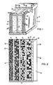
- Fig. 2 shows in detail the electrode 12 of Fig. 1.
- the electrode is of a laminar construction.
- Cathode 12 is shown with a plurality of active material sections, making up the active layer 17, and a porous hydrophobic backing sheet 14 laminated thereto.
- Current collectors 19 used in metal-air battery applications are shown in the active layer 17 and are adapted for electrical connection to the circuit. In the preferred embodiment, at least two current collectors are used.
- the active material 30, comprises both hydrophilic agglomerates 31 and hydrophobic agglomerates 32 which coat, and bond to, and at least partially impregnate the current collectors 19, although such impregnation is not shown for sake of simplicity.
- the current collector 19 can be made of expanded metal, such as nickel. It can also be made from expanded nickel coated iron or steel. Preferably it is made from nickel coated iron or steel fiber metal, or uncoated nickel, iron or steel fiber metal, for example, nickel or steel wool. Most preferably the metal fibers are diffusion bonded together and exceed 1.5 inches in length. Fiber diameters are usually from about 0.0002 inch to about 0.005 inch. Diffusion bonding techniques are well known, and described in detail in U.S. Patent Specification No. 4,152,489.
- the current collector plaque 19 should have a porosity of from 75% to 95% and a thickness of between 0.005 inch and 0.050 inch. For fuel cell electrode applications, current collectors can be excluded.
- the active layer 17 is from 0.010 inch to 0.150 inch thick for metal-air battery applications and from 0.005 inch to 0.030 inch thick for fuel cell applications.
- the porous hydrophobic backing sheet 14 is from 0.005 inch to 0.020 inch thick for metal-air battery applications and from 0.002 inch to 0.020 inch thick for fuel cell application.
- the porous backing sheet 14 can comprise a porous pressed layer or sheet of particulate polytetrafluoroethylene or milled, fibrillated polytetrafluoroethylene fibers alone, or with either or a combination of unfibril- lated fluorinated ethylene propylene fibers, carbon particles or fibers, polypropylene, polyethylene, and the like, as is well known in the art.
- the plurality of active material sections constituting active layer 17, after their formation, for example, by individual cold pressing, which is particularly applicable for metal-air battery use, can be hot press or roll laminated together to form a consolidated laminar structure.
- the consolidated active layer 17 and the hydrophobic sheet 14 can then be press or roll laminated together at from 190°C to 350°C, with an air pressure of from 25 psi. to 750 psi.
- the porous backing sheet can be attached during the active layer lamination process.
- the catalytically active material 30, constituting the active layer comprises a mixture of both catalytically active hydrophobic and catalytically active hydrophilic material, both of whose agglomerates increase in particle size diameter from the electrolyte contact side 33 to the air contact side 34 of the electrode. Additionally, the weight percent of hydrophobic material in the active layer 17 increases from the electrolyte side 33 to the air side 34.
- the weight percent ratio of (active hydrophilic material):(active hydrophobic material) in the active layer 17 is about (30% to 50%):(50% to 70%), usually about 40%:60%.
- the weight ratio of (active hydrophilic material):(active hydrophobic material) through the thickness of the active layer 17 can range from about (1):(0.2) at the electrolyte contact side 33 to about (1):(5) at the air contact side, i.e., the porous backing sheet contact side.
- active material section A may contain 1.5 parts of hydrophilic material having a particle size of about 800 microns and 0.5 part of hydrophobic material having a particle size of about 650 microns.
- Section B may contain 1.5 parts of hydrophilic material having a particle size of about 800 microns and 1.5 parts of hydrophobic material having a particle size of about 650 microns.
- Section C may contain 1.0 part of hydrophilic material having a particle size of about 1,000 microns and 2.0 parts of hydrophobic material having a particle size of about 700 microns.
- Section D may contain 0.5 part of hydrophilic material having a particle size of about 1,100 microns and 2.5 parts of hydrophobic material having a particle size of about 1,100 microns.
- the particle size of hydrophilic material increases from side 33 to side 34, i.e., from 800 to 1,100 microns
- the particle size of hydrophobic material also increases from side 33 to side 34, i.e., from 650 to 1,100 microns
- the weight ratio of (hydrophilic material):(hydrophobic material) increased from side 33 to side 34 i.e., from (1): (0.3) to (1):(5).
- the active layer be electrochemically active throughout, that the active material comprise both hydrophilic material and hydrophobic material in a homogenous admixed combination in each active section, and that there be both an agglomerate particle size gradient and a weight ratio gradient from the electrolyte contact side to the air contact side through the active layer of the electrode structure.
- hydrophilic material means agglomerates through which electrolyte can readily permeate and flow.
- hydrophobic material means agglomerates which tend to retain electrolyte or prevent its flow, yet which easily pass air.
- catalyst is equally distributed throughout the active layer, even in section D, next to the porous backing layer 14; and bonding/nonwetting material is equally distributed throughout the active layer, even in section A next to the electrolyte contact surface 33, as described hereinafter.
- the catalytically active material, 30 in Fig. 2, contained in each active material section A, B, C and D, comprises: an oxygen absorption/reduction carbon, preferably having a BET total surface area of from about 30 square meters per gram to about 300 square meters per gram; a suitable catalyst, such as silver preferably coated or otherwise contained on or in the carbon particles; preferably, a low oxygen overvoltage metal additive such as CoW0 4 , WS 2 , nickel spinels, and preferably NiS, FeW0 4 , WC, WC coated with 1 to 20 weight percent Co, and their mixtures; and a fluorocarbon particle dispersion, preferably a polytetrafluoroethylene dispersion, as a bonding/nonwetting material, where the dispersion agent is a heat vaporizable or decomposable organic material that is effective to reduce surface tension between the fluorocarbon and other particles and promote electrolyte capillary flow between particles in the active material.
- an oxygen absorption/reduction carbon
- Useful dispersion agents include anionic surfactants, such as sodium alkaryl polyether sulfonate, sodium alkaryl polyether sulfate, sodium alkaryl ether sulfate, dioctyl sodium sulfosuccinate, and phosphate esters in acid form, and the like, and their mixtures; and preferably non-ionic surfactants, such as octyl phenol ether alcohol, octyl phenol polyether alcohol, nonyl phenol polyether alcohol, alkylpolyether alcohol, alkylaryl polyethylene glycol ether, and the like, and their mixtures, and mixtures with anionic surfactants, as are well known in the art. Cationic surfactants, having a negative charge, tend to repel electrolyte penetration and are not particularly useful.
- anionic surfactants such as sodium alkaryl polyether sulfonate, sodium alkaryl polyether sulfate, sodium alkaryl ether sulfate, dio
- the useful carbon in this invention is preferably in a fluffy form comprising discrete particles in a chain-like form, such as acetylene black. If in a pressed pellet form, it can be ground to a useful particle size.
- Acetylene black has a low resistivity of from 0.035 to 0.22 ohms/cubic inch at 2,500 psi, making it an excellent electron conductor. It has a bulk density of about 1.20 lb./cubic foot, a particle size of from 0.005 to 0.13 micron, and each particle contains few pore openings greater than 0.002 micron on its external surface. Almost all of its surface area is external, there being few internal channels. Certain channel carbon black materials are also useful. The preferred BET total surface area range for the carbon is from 30 to 300 square meters per gram.
- the carbon acts as a surface to evolve oxygen during electrode charging.
- the carbon also usually serves as a surface for the silver, nickel, platinum or other suitable catalyst, depending on electrode application, which can be applied to the carbon.
- the preferred catalyst for metal-air battery applications carbon is mixed with AgN0 3 solution and the silver precipitated out and onto the carbon with hydrazine.
- BET Brunauer, Emmett and Teller
- all of the hereinbefore described catalytically active material is air dried at from 25°C to 30°C for 12 to 48 hours, providing an active all hydrophilic material. Then a portion of this hydrophilic material is heat treated by oven baking at from 250°C to 325°C for about 1 to 3 hours in air or a flowing gas atmosphere. This heat treatment causes the dispersion agent for the fluorocarbon to thermally decompose or vaporize to provide a hydrophobic material which will retain electrolyte because the dispersion agent, usually a surfactant, is not present to reduce surface tension and allow good capillary flow of the electrolyte.
- the air dried portion and the heat treated portion are size graded to provide agglomerates or particle masses ranging from 150 microns to 2,000 microns, for metal-air battery applications, and from 30 microns to 300 microns for fuel cell applications. They are then admixed in the appropriate amounts to provide the weight range gradient described hereinbefore.
- agglomerates is meant a combined mass comprising a plurality of the extremely fine carbon particles together with the coarser fluorocarbon and the metal addive particles which are particularly useful in metal-air battery applications. These range in particle size from 0.5 to 50 microns for the former, and 50 to 200 microns for the latter.
- the amount of fluorocarbon bonding/nonwetting solids may vary from about 10 weight percent to about 50 weight percent of the total composition.
- the fluorocarbon dispersion contains from 50% to 60% fluorocarbon solids, and 5% to 10% dispersing agent, with the rest of the dispersion as water.
- Low oxygen overvoltage material can be added in the amount of from 0.25 part to 5 parts/ part carbon. These materials may act as pore formers and in some instances prevent catalyst dissolution.
- the carbon will generally contain from 2 weight percent to 10 weight percent, preferably from 2 to 5 weight percent silver or other suitable catalyst.
- Electrodes are particularly useful in electrochemical energy cells, which can be combined to form metal/air batteries, where the metal electrode can be iron, zinc, cadmium, or aluminum with alkali hydroxide electrolyte disposed between and contacting the electrodes.
- Electrodes can also find use as electrodes in a variety of fuel cells, such as room temperature alkaline fuel cells and high temperature phosphoric acid fuel cells, both of which are well known in the art.
- a fuel electrode contacts a fuel, such as hydrogen gas and an air electrode contacts air or oxygen, and electrolyte contacts the fuel electrode and the air electrode.
- the electrode of this invention can be used as either the fuel electrode or the air electrode, and the electrolyte, such as potassium hydroxide or phosphoric acid, is disposed between the fuel and air electrodes.
- the electrolyte such as potassium hydroxide or phosphoric acid
- a 4.5 inch x 4.5 inch air electrode was made. Dry acetylene carbon black particles, having a BET surface area of from about 60 to 70 square meters per gram (sold commercially by Shawinigan Products Corp. under the tradename Shawinigan Black) were mixed with AgN0 3 in a wet slurry. Hydrazine was then added to precipitate the silver on the carbon particles. Excess water was then vacuumed off and the paste allowed to air dry for 24 hours. Sufficient AgN0 3 solution was used to provide a 3 to 4 weight percent silver content on the surface of the carbon particles.
- this silverized carbon powder was added 4.5 grams of NiS; 4.5 grams of FeW0 4 ; 4.5 grams of WC coated with 12 weight percent Co; 12 grams of aqueous polytetrafluoroethylene dispersion containing 7.2 grams of polytetraethylene solids and about 1.0 gram of an octylphenol polyether alcohol non-ionic surfactant dispersing agent; and 170 ml. of water, to form a slurry.
- the slurry was then air dried on a screen at 25°C for 24 hours to provide an active hydrophilic material.
- the mixture of low oxygen overvoltage materials was present in an amount of about 0.45 part/part carbon, and the polytetraethylene solids constituted about 14 weight percent of the air dried, catalyzed material. About 60 weight percent of the air dried, catalyzed material was placed in an oven and baked at 300°C for 2 hours, to vaporize and decompose the nonionic surfactant and provide a heat treated active hydrophobic material. Without the surfactant, this material would provide little capillary penetration of electrolyte.
- Both the active hydrophilic material and the active hydrophobic material had the same amount of catalyst and polytetrafluoroethylene present, and both were sieved and size graded to provide batches of hydrophilic agglomerates having particle sizes of 793 microns and 1,098 microns, and batches of hydrophobic agglomerates having particle sizes of 660 microns, 793 microns, and 1,098 microns.
- Each section of catalyzed active material was cold pressed into its corresponding nickel plaque at 2,500 lb./sq. inch, to provide a coating on and at least partial impregnation of the corresponding plaque.
- a hydrophobic sheet was made by mixing carbon black particles and polytetrafluoroethylene in a mill, to fibrillate the polytetrafluoroethylene, and then cold pressing the milled admixture at 2,500 lb./sq. inch into a sheet form.
- the hydrophobic sheet was then placed on the platen of a hot bed press and sections D, C, B and A respectively superimposed thereon to provide an electrode stack up.
- the entire stack up was then heat and pressure consolidated in the hot bed press at 4,000 lb./sq. inch and 300°C, to provide a unitary air electrode similar in structure to that shown in Fig. 2.
- the active layer of the air electrode consisted of 38 weight % hydrophilic material and 62 weight % hydrophobic material excluding plaque weight, and the weight ratio of active hydrophilic material:active hydrophobic material ranged from 1.2:0.8 or 1:0.67 for the section next to electrolyte, to 0.8:(0.5+1.7) or 1:2.5 for the section next to the hydrophobic sheet on the air side. Also, the particle size of the hydrophilic material increased from 793 to 1,098 microns and the particle size of the hydrophobic material increased from 660 to 1,098 microns from the electrolyte to the air side.
- the consolidated air electrode, containing 4 active material sections and 4 current collectors was used as one side of a square plastic container filled with a 25 wt.% KOH electrolyte solution, where the hydrophobic sheet contacted an air source and section A of the air electrode contacted the electrolyte.
- the plastic framed the air electrode, similarly as shown in Fig. 1 of the drawings, so that the active surface was reduced to about 3-1/4 inch x 3-3/4 inch.
- a flat nickel sheet formed the opposite wall of the cell acting as a counter electrode.
- a polytetrafluoroethylene sheet was used to cover the side of the nickel counter electrode not in contact with electrolyte.
- the air electrode of this invention having both a size and weight grading across its active layer, exhibited stable electrical characteristics, with no major potential changes, indicating no uncontrolled electrolyte flooding of any active regions and no structural delamina- tions in any active regions due to oxygen entrapment. Testing was continued and the curve remained stable up to 300 cycles. Such dramatic results indicate the superiority of the air electrode of this invention, and indicate its usefulness in a non-flooding metal-air battery.
- a comparative material represented by curve B in each graph is described below.
- a 4.5 inch x 4.5 inch air electrode was made utilizing four 4.5 inch x 4.5 inch x 0.01 inch thick diffusion bonded, 94% porous, nickel fiber wool plaques as current collectors.
- the ingredients and amounts for the active material were the same as used in Example 1, so that the mixture of low oxygen overvoltage materials was present in an amount of about 0.45 part/part carbon, and the polytetraethylene solids constituted about 14 weight percent of the air dried, catalyzed material.
- a small percent of the air dried, catalyzed material was baked, as described in Example 1, to provide a hydrophobic material.
- Both the active hydrophilic material and the active hydrophobic material had the same amount of catalyst and polytetrafluoroethylene present, and both were sieved and size graded to provide hydrophilic and hydrophobic agglomerates, both having particle sizes of approximately 2,500 microns.
- each section of catalyzed active material was cold pressed into its corresponding nickel plaque, and a stack up prepared and hot bed pressed to a hydrophobic sheet to provide a unitary air electrode containing 4 active material sections and 4 current collectors.
- the size and weight graded, multi-ply laminar electrodes of this invention can also be used in fuel cell applications.
Landscapes
- Chemical & Material Sciences (AREA)
- Chemical Kinetics & Catalysis (AREA)
- Electrochemistry (AREA)
- General Chemical & Material Sciences (AREA)
- Inert Electrodes (AREA)
Applications Claiming Priority (4)
| Application Number | Priority Date | Filing Date | Title |
|---|---|---|---|
| US41236982A | 1982-08-27 | 1982-08-27 | |
| US412369 | 1982-08-27 | ||
| US442706 | 1982-11-18 | ||
| US06/442,706 US4444852A (en) | 1982-08-27 | 1982-11-18 | Size and weight graded multi-ply laminar electrodes |
Publications (3)
| Publication Number | Publication Date |
|---|---|
| EP0110491A2 true EP0110491A2 (de) | 1984-06-13 |
| EP0110491A3 EP0110491A3 (en) | 1985-09-18 |
| EP0110491B1 EP0110491B1 (de) | 1988-08-24 |
Family
ID=27021755
Family Applications (1)
| Application Number | Title | Priority Date | Filing Date |
|---|---|---|---|
| EP83302293A Expired EP0110491B1 (de) | 1982-08-27 | 1983-04-22 | Nach Grösse und Gewicht abgestufte mehrfach laminierte Gasdiffusionselektroden |
Country Status (3)
| Country | Link |
|---|---|
| US (1) | US4444852A (de) |
| EP (1) | EP0110491B1 (de) |
| DE (1) | DE3377843D1 (de) |
Cited By (8)
| Publication number | Priority date | Publication date | Assignee | Title |
|---|---|---|---|---|
| EP0241432A3 (en) * | 1986-03-07 | 1988-12-14 | Tanaka Kikinzoku Kogyo K.K. | Gas permeable electrode |
| WO1993003505A1 (en) * | 1991-07-26 | 1993-02-18 | International Fuel Cells Corporation | High current acid fuel cell electrodes |
| WO1993003506A1 (en) * | 1991-07-26 | 1993-02-18 | International Fuel Cells Corporation | High current alkaline fuel cell electrodes |
| WO1994010714A1 (en) * | 1992-10-30 | 1994-05-11 | Aer Energy Resources, Inc. | Bifunctional airelectrode |
| US5480735A (en) * | 1990-06-25 | 1996-01-02 | International Fuel Cells Corporation | High current alkaline fuel cell electrodes |
| US5702839A (en) * | 1993-11-23 | 1997-12-30 | Johnson Matthey Public Limited Company | Manufacture of electrodes |
| EP1519433A1 (de) | 2003-09-26 | 2005-03-30 | Samsung SDI Co., Ltd. | Diffusionselektrode für Brennstoffzellen |
| CN102544633A (zh) * | 2010-12-07 | 2012-07-04 | 中国电子科技集团公司第十八研究所 | 一种防阻塞锂空气电池的制备方法 |
Families Citing this family (52)
| Publication number | Priority date | Publication date | Assignee | Title |
|---|---|---|---|---|
| US4704340A (en) * | 1985-04-08 | 1987-11-03 | Gas Research Institute | Molten carbonate electrolyte creepage barrier |
| US4816431A (en) * | 1986-04-03 | 1989-03-28 | Nagakazu Furuya | Process for preparing materials for reaction layer of gas permeable electrode |
| US4822698A (en) * | 1987-05-15 | 1989-04-18 | Westinghouse Electric Corp. | Seawater power cell |
| US4877694A (en) * | 1987-05-18 | 1989-10-31 | Eltech Systems Corporation | Gas diffusion electrode |
| US4855194A (en) * | 1988-02-05 | 1989-08-08 | The United States Of America As Represented By The United States Department Of Energy | Fuel cell having electrolyte inventory control volume |
| US5232561A (en) * | 1989-12-15 | 1993-08-03 | Tanaka Kikinzoku Kogyo K.K. | Electrolytic method of preparing compounds with a gas permeable electrode |
| JPH04345763A (ja) * | 1991-05-22 | 1992-12-01 | Fuji Electric Co Ltd | リン酸型燃料電池のマトリックスおよびその製造方法 |
| US5618392A (en) * | 1991-10-31 | 1997-04-08 | Tanaka Kikinzoku Kogyo K.K. | Gas diffusion electrode |
| CA2077474A1 (en) * | 1992-02-21 | 1993-08-22 | Carl W. Townsend | Dual porosity gas evolving electrode |
| JP3245929B2 (ja) * | 1992-03-09 | 2002-01-15 | 株式会社日立製作所 | 燃料電池及びその応用装置 |
| US5545492A (en) * | 1992-10-14 | 1996-08-13 | National Power Plc | Electrochemical apparatus for power delivery utilizing an air electrode |
| US5318862A (en) * | 1993-09-22 | 1994-06-07 | Westinghouse Electric Corp. | Bifunctional gas diffusion electrodes employing wettable, non-wettable layered structure using the mud-caking concept |
| US5639568A (en) * | 1995-10-16 | 1997-06-17 | Aer Energy Resources, Inc. | Split anode for a dual air electrode cell |
| US5783325A (en) * | 1996-08-27 | 1998-07-21 | The Research Foundation Of State Of New York | Gas diffusion electrodes based on poly(vinylidene fluoride) carbon blends |
| US6660680B1 (en) | 1997-02-24 | 2003-12-09 | Superior Micropowders, Llc | Electrocatalyst powders, methods for producing powders and devices fabricated from same |
| JPH11204114A (ja) * | 1998-01-20 | 1999-07-30 | Daikin Ind Ltd | 電極材料 |
| US6753108B1 (en) * | 1998-02-24 | 2004-06-22 | Superior Micropowders, Llc | Energy devices and methods for the fabrication of energy devices |
| US7517606B2 (en) * | 1998-02-24 | 2009-04-14 | Cabot Corporation | Fuel cells and batteries including metal-carbon composite powders |
| US7066976B2 (en) * | 1998-02-24 | 2006-06-27 | Cabot Corporation | Method for the production of electrocatalyst powders |
| US6967183B2 (en) * | 1998-08-27 | 2005-11-22 | Cabot Corporation | Electrocatalyst powders, methods for producing powders and devices fabricated from same |
| EP1231656B1 (de) * | 1999-09-21 | 2009-04-29 | Panasonic Corporation | Polymer-elektrolyt-brennstoffzelle und herstellungsverfahren dafür |
| US6368751B1 (en) * | 1999-10-08 | 2002-04-09 | Reves, Inc. | Electrochemical electrode for fuel cell |
| US6632557B1 (en) | 1999-10-26 | 2003-10-14 | The Gillette Company | Cathodes for metal air electrochemical cells |
| EP1184918B1 (de) * | 2000-08-28 | 2009-10-14 | Nissan Motor Co., Ltd. | Wiederaufladbare Lithiumionenbatterie |
| US6794074B2 (en) * | 2000-10-12 | 2004-09-21 | Rayovac Corporation | Air manager for metal-air cells |
| ATE509380T1 (de) * | 2001-05-24 | 2011-05-15 | Ray O Vac Corp | Ionenleitendes additiv für zinkanoden in alkalischen elektrochemischen zellen |
| EP1298745B1 (de) * | 2001-09-28 | 2010-04-21 | Panasonic Corporation | Polymer-Elektrolyt Brennstoffzelle |
| US7332238B2 (en) * | 2002-09-06 | 2008-02-19 | The Gillette Company | Electrochemical cells and systems |
| US20040048146A1 (en) * | 2002-09-06 | 2004-03-11 | David Adamson | Electrochemical cells and systems |
| JP2004288388A (ja) * | 2003-03-19 | 2004-10-14 | Aisin Seiki Co Ltd | 燃料電池用電極およびその製造方法および燃料電池 |
| US7066970B2 (en) * | 2003-05-09 | 2006-06-27 | The Gillette Company | Electrochemical cells |
| JP4917737B2 (ja) * | 2003-11-12 | 2012-04-18 | 日産自動車株式会社 | 燃料電池用電解質膜および燃料電池 |
| US20070048575A1 (en) * | 2005-08-30 | 2007-03-01 | Rovcal, Inc. | Electrochemical cells containing spun mercury-amalgamated zinc particles having improved physical characteristics |
| US20070048576A1 (en) * | 2005-08-30 | 2007-03-01 | Rovcal, Inc. | Electrochemical cells containing spun mercury-amalgamated zinc particles having improved physical characteristics |
| US7563537B2 (en) * | 2005-11-30 | 2009-07-21 | Rovcal, Inc. | Ionically conductive clay additive for use in electrochemical cells |
| KR100658688B1 (ko) * | 2005-12-19 | 2006-12-15 | 삼성에스디아이 주식회사 | 연료 전지용 막-전극 어셈블리 및 이를 포함하는 연료 전지시스템 |
| US20070141432A1 (en) * | 2005-12-21 | 2007-06-21 | General Electric Company | Third electrode frame structure and method related thereto |
| KR100738059B1 (ko) * | 2006-02-08 | 2007-07-10 | 삼성에스디아이 주식회사 | 연료전지용 전극, 그 제조방법 및 이를 구비한 연료전지 |
| GB0604598D0 (en) * | 2006-03-07 | 2006-04-19 | Dfc Energy Ltd | Improvements in and relating to fuel cells |
| GB0604597D0 (en) * | 2006-03-07 | 2006-04-19 | Dfc Energy Ltd | A fuel cell assembly |
| WO2007102026A2 (en) * | 2006-03-07 | 2007-09-13 | Afc Energy Plc | Electrodes of a fuel cell |
| KR20070095055A (ko) * | 2006-03-20 | 2007-09-28 | 삼성에스디아이 주식회사 | 연료 전지용 막-전극 어셈블리, 이의 제조방법 및 이를포함하는 연료 전지 시스템 |
| KR20070099120A (ko) * | 2006-04-03 | 2007-10-09 | 삼성에스디아이 주식회사 | 연료 전지용 애노드 전극, 이를 포함하는 막-전극 어셈블리및 이를 포함하는 연료 전지 시스템 |
| KR20070119905A (ko) * | 2006-06-16 | 2007-12-21 | 삼성에스디아이 주식회사 | 연료 전지용 막-전극 어셈블리 및 이를 포함하는 연료 전지시스템 |
| AU2010210323B2 (en) * | 2009-02-05 | 2014-01-09 | Evt Power, Inc. | Multiply-conductive matrix for battery current collectors |
| MX2012004237A (es) * | 2009-10-08 | 2012-10-03 | Fluidic Inc | Celda metalica-aire recargable con sistema de manejo de flujo. |
| WO2011109815A1 (en) * | 2010-03-05 | 2011-09-09 | A123 Systems, Inc. | Design and fabrication of electrodes with gradients |
| CN102487155A (zh) * | 2010-12-06 | 2012-06-06 | 中国电子科技集团公司第十八研究所 | 多层电解质锂空气电池 |
| CN102487154A (zh) * | 2010-12-06 | 2012-06-06 | 中国电子科技集团公司第十八研究所 | 一种多层电解质锂空气电池的制备方法 |
| US9455438B2 (en) * | 2012-04-13 | 2016-09-27 | Lg Chem, Ltd. | Method for preparing electrode mix and the electrode mix prepared by using the same |
| US10593959B2 (en) * | 2014-12-26 | 2020-03-17 | Nippon Steel Corporation | Electrode for metal-air battery |
| AU2023213702A1 (en) | 2022-01-28 | 2024-08-01 | Form Energy, Inc. | Bifacial sealed gas diffusion electrode |
Family Cites Families (9)
| Publication number | Priority date | Publication date | Assignee | Title |
|---|---|---|---|---|
| DE1250791B (de) * | 1960-07-04 | 1967-09-28 | Siemens Aktiengesellschaft, Berlin und München, Erlangen; VARTA AKTIENGESELLSCHAFT, Frankfurt/Main | Zweischichtige Sauerstoff-Diffusionselektrode |
| US3423247A (en) * | 1963-06-07 | 1969-01-21 | Union Carbide Corp | Porous conductive electrode having at least two zones |
| SE385168B (sv) * | 1971-03-29 | 1976-06-08 | Zlehit Pri Ban | Sett att framstella pulverartat hydrofoberat elektrodmaterial for gasdiffusionselektroder |
| GB1392353A (en) * | 1972-04-11 | 1975-04-30 | Zlehit Pri Ban | Gasdiffusion electrode |
| US3840407A (en) * | 1972-06-19 | 1974-10-08 | Textron Inc | Composite porous electrode |
| US4066823A (en) * | 1973-09-11 | 1978-01-03 | Armstrong William A | Method for a low temperature oxygen electrode |
| US3977901A (en) * | 1974-10-23 | 1976-08-31 | Westinghouse Electric Corporation | Metal/air cells and improved air electrodes for use therein |
| US4152489A (en) * | 1977-08-26 | 1979-05-01 | Westinghouse Electric Corp. | Multi-ply laminar pasted air electrodes |
| US4341848A (en) * | 1981-03-05 | 1982-07-27 | The United States Of America As Represented By The United States Department Of Energy | Bifunctional air electrodes containing elemental iron powder charging additive |
-
1982
- 1982-11-18 US US06/442,706 patent/US4444852A/en not_active Expired - Fee Related
-
1983
- 1983-04-22 DE DE8383302293T patent/DE3377843D1/de not_active Expired
- 1983-04-22 EP EP83302293A patent/EP0110491B1/de not_active Expired
Cited By (9)
| Publication number | Priority date | Publication date | Assignee | Title |
|---|---|---|---|---|
| EP0241432A3 (en) * | 1986-03-07 | 1988-12-14 | Tanaka Kikinzoku Kogyo K.K. | Gas permeable electrode |
| US5480735A (en) * | 1990-06-25 | 1996-01-02 | International Fuel Cells Corporation | High current alkaline fuel cell electrodes |
| WO1993003505A1 (en) * | 1991-07-26 | 1993-02-18 | International Fuel Cells Corporation | High current acid fuel cell electrodes |
| WO1993003506A1 (en) * | 1991-07-26 | 1993-02-18 | International Fuel Cells Corporation | High current alkaline fuel cell electrodes |
| WO1994010714A1 (en) * | 1992-10-30 | 1994-05-11 | Aer Energy Resources, Inc. | Bifunctional airelectrode |
| US5702839A (en) * | 1993-11-23 | 1997-12-30 | Johnson Matthey Public Limited Company | Manufacture of electrodes |
| US5871860A (en) * | 1993-11-23 | 1999-02-16 | Johnson Matthey Public Limited Company | Manufacture of electrodes |
| EP1519433A1 (de) | 2003-09-26 | 2005-03-30 | Samsung SDI Co., Ltd. | Diffusionselektrode für Brennstoffzellen |
| CN102544633A (zh) * | 2010-12-07 | 2012-07-04 | 中国电子科技集团公司第十八研究所 | 一种防阻塞锂空气电池的制备方法 |
Also Published As
| Publication number | Publication date |
|---|---|
| EP0110491A3 (en) | 1985-09-18 |
| DE3377843D1 (en) | 1988-09-29 |
| EP0110491B1 (de) | 1988-08-24 |
| US4444852A (en) | 1984-04-24 |
Similar Documents
| Publication | Publication Date | Title |
|---|---|---|
| EP0110491B1 (de) | Nach Grösse und Gewicht abgestufte mehrfach laminierte Gasdiffusionselektroden | |
| US4957826A (en) | Rechargeable metal-air battery | |
| US6291090B1 (en) | Method for making metal-air electrode with water soluble catalyst precursors | |
| EP0580278B1 (de) | Einmal-Durchgang Gasdiffusionselektrode | |
| US4341848A (en) | Bifunctional air electrodes containing elemental iron powder charging additive | |
| US3977901A (en) | Metal/air cells and improved air electrodes for use therein | |
| US4448856A (en) | Battery and fuel cell electrodes containing stainless steel charging additive | |
| US5306579A (en) | Bifunctional metal-air electrode | |
| US6069107A (en) | Recharge catalyst with thin film carbon coating, metal-air electrode including said catalyst and methods for making said catalyst and electrode | |
| EP1977475B1 (de) | Bifunktionale luftelektrode | |
| CA2282434C (en) | Gas diffusion electrode with reduced diffusing capacity for water and polymer electrolyte membrane fuel cells | |
| US4585711A (en) | Hydrogen electrode for a fuel cell | |
| US5441823A (en) | Process for the preparation of gas diffusion electrodes | |
| JP2002535818A (ja) | 空気−金属蓄電池のための触媒空気陰極 | |
| US3600230A (en) | Gas-depolarized cell with hydrophobic-resin-containing cathode | |
| US3549423A (en) | Method for manufacturing foam type electrode | |
| US5053375A (en) | Electrochemical cathode and materials therefor | |
| US3733221A (en) | Gas diffusion electrode | |
| US3536537A (en) | Method of making electrode having improved gas-recombination properties | |
| US5122426A (en) | Gas-tight, sealed alkaline secondary cell | |
| US3935027A (en) | Oxygen-reduction electrocatalysts for electrodes | |
| US6428931B1 (en) | Methods for making oxygen reduction catalyst using micelle encapsulation and metal-air electrode including said catalyst | |
| JPH0365624B2 (de) | ||
| Mrha et al. | Plastic-bonded electrodes for nickel—cadmium accumulators. VIII. Study of oxygen recombination rate on plastic-bonded cadmium electrodes provided with active carbon catalyst | |
| JPS5854563A (ja) | 空気電極の触媒層 |
Legal Events
| Date | Code | Title | Description |
|---|---|---|---|
| PUAI | Public reference made under article 153(3) epc to a published international application that has entered the european phase |
Free format text: ORIGINAL CODE: 0009012 |
|
| AK | Designated contracting states |
Designated state(s): DE FR GB IT NL SE |
|
| PUAL | Search report despatched |
Free format text: ORIGINAL CODE: 0009013 |
|
| AK | Designated contracting states |
Designated state(s): DE FR GB IT NL SE |
|
| 17P | Request for examination filed |
Effective date: 19860318 |
|
| 17Q | First examination report despatched |
Effective date: 19870714 |
|
| GRAA | (expected) grant |
Free format text: ORIGINAL CODE: 0009210 |
|
| AK | Designated contracting states |
Kind code of ref document: B1 Designated state(s): DE FR GB IT NL SE |
|
| REF | Corresponds to: |
Ref document number: 3377843 Country of ref document: DE Date of ref document: 19880929 |
|
| ET | Fr: translation filed | ||
| ITF | It: translation for a ep patent filed | ||
| PLBE | No opposition filed within time limit |
Free format text: ORIGINAL CODE: 0009261 |
|
| STAA | Information on the status of an ep patent application or granted ep patent |
Free format text: STATUS: NO OPPOSITION FILED WITHIN TIME LIMIT |
|
| 26N | No opposition filed | ||
| ITTA | It: last paid annual fee | ||
| PGFP | Annual fee paid to national office [announced via postgrant information from national office to epo] |
Ref country code: FR Payment date: 19940317 Year of fee payment: 12 |
|
| PGFP | Annual fee paid to national office [announced via postgrant information from national office to epo] |
Ref country code: SE Payment date: 19940321 Year of fee payment: 12 |
|
| PGFP | Annual fee paid to national office [announced via postgrant information from national office to epo] |
Ref country code: GB Payment date: 19940324 Year of fee payment: 12 |
|
| PGFP | Annual fee paid to national office [announced via postgrant information from national office to epo] |
Ref country code: NL Payment date: 19940430 Year of fee payment: 12 |
|
| PGFP | Annual fee paid to national office [announced via postgrant information from national office to epo] |
Ref country code: DE Payment date: 19940630 Year of fee payment: 12 |
|
| EAL | Se: european patent in force in sweden |
Ref document number: 83302293.2 |
|
| PG25 | Lapsed in a contracting state [announced via postgrant information from national office to epo] |
Ref country code: GB Effective date: 19950422 |
|
| PG25 | Lapsed in a contracting state [announced via postgrant information from national office to epo] |
Ref country code: SE Effective date: 19950423 |
|
| PG25 | Lapsed in a contracting state [announced via postgrant information from national office to epo] |
Ref country code: NL Effective date: 19951101 |
|
| GBPC | Gb: european patent ceased through non-payment of renewal fee |
Effective date: 19950422 |
|
| PG25 | Lapsed in a contracting state [announced via postgrant information from national office to epo] |
Ref country code: FR Effective date: 19951229 |
|
| NLV4 | Nl: lapsed or anulled due to non-payment of the annual fee |
Effective date: 19951101 |
|
| PG25 | Lapsed in a contracting state [announced via postgrant information from national office to epo] |
Ref country code: DE Effective date: 19960103 |
|
| EUG | Se: european patent has lapsed |
Ref document number: 83302293.2 |
|
| REG | Reference to a national code |
Ref country code: FR Ref legal event code: ST |