EP0109620A2 - Source de chaleur chauffée par combustible - Google Patents
Source de chaleur chauffée par combustible Download PDFInfo
- Publication number
- EP0109620A2 EP0109620A2 EP83111256A EP83111256A EP0109620A2 EP 0109620 A2 EP0109620 A2 EP 0109620A2 EP 83111256 A EP83111256 A EP 83111256A EP 83111256 A EP83111256 A EP 83111256A EP 0109620 A2 EP0109620 A2 EP 0109620A2
- Authority
- EP
- European Patent Office
- Prior art keywords
- heat source
- flap
- fuel
- bypass
- heated heat
- Prior art date
- Legal status (The legal status is an assumption and is not a legal conclusion. Google has not performed a legal analysis and makes no representation as to the accuracy of the status listed.)
- Withdrawn
Links
Images


Classifications
-
- F—MECHANICAL ENGINEERING; LIGHTING; HEATING; WEAPONS; BLASTING
- F23—COMBUSTION APPARATUS; COMBUSTION PROCESSES
- F23L—SUPPLYING AIR OR NON-COMBUSTIBLE LIQUIDS OR GASES TO COMBUSTION APPARATUS IN GENERAL ; VALVES OR DAMPERS SPECIALLY ADAPTED FOR CONTROLLING AIR SUPPLY OR DRAUGHT IN COMBUSTION APPARATUS; INDUCING DRAUGHT IN COMBUSTION APPARATUS; TOPS FOR CHIMNEYS OR VENTILATING SHAFTS; TERMINALS FOR FLUES
- F23L11/00—Arrangements of valves or dampers after the fire
- F23L11/02—Arrangements of valves or dampers after the fire for reducing draught by admission of air to flues
-
- F—MECHANICAL ENGINEERING; LIGHTING; HEATING; WEAPONS; BLASTING
- F23—COMBUSTION APPARATUS; COMBUSTION PROCESSES
- F23L—SUPPLYING AIR OR NON-COMBUSTIBLE LIQUIDS OR GASES TO COMBUSTION APPARATUS IN GENERAL ; VALVES OR DAMPERS SPECIALLY ADAPTED FOR CONTROLLING AIR SUPPLY OR DRAUGHT IN COMBUSTION APPARATUS; INDUCING DRAUGHT IN COMBUSTION APPARATUS; TOPS FOR CHIMNEYS OR VENTILATING SHAFTS; TERMINALS FOR FLUES
- F23L13/00—Construction of valves or dampers for controlling air supply or draught
- F23L13/02—Construction of valves or dampers for controlling air supply or draught pivoted about a single axis but having not other movement
-
- F—MECHANICAL ENGINEERING; LIGHTING; HEATING; WEAPONS; BLASTING
- F23—COMBUSTION APPARATUS; COMBUSTION PROCESSES
- F23L—SUPPLYING AIR OR NON-COMBUSTIBLE LIQUIDS OR GASES TO COMBUSTION APPARATUS IN GENERAL ; VALVES OR DAMPERS SPECIALLY ADAPTED FOR CONTROLLING AIR SUPPLY OR DRAUGHT IN COMBUSTION APPARATUS; INDUCING DRAUGHT IN COMBUSTION APPARATUS; TOPS FOR CHIMNEYS OR VENTILATING SHAFTS; TERMINALS FOR FLUES
- F23L3/00—Arrangements of valves or dampers before the fire
-
- F—MECHANICAL ENGINEERING; LIGHTING; HEATING; WEAPONS; BLASTING
- F23—COMBUSTION APPARATUS; COMBUSTION PROCESSES
- F23N—REGULATING OR CONTROLLING COMBUSTION
- F23N3/00—Regulating air supply or draught
- F23N3/06—Regulating air supply or draught by conjoint operation of two or more valves or dampers
- F23N3/065—Regulating air supply or draught by conjoint operation of two or more valves or dampers using mechanical means
-
- F—MECHANICAL ENGINEERING; LIGHTING; HEATING; WEAPONS; BLASTING
- F24—HEATING; RANGES; VENTILATING
- F24H—FLUID HEATERS, e.g. WATER OR AIR HEATERS, HAVING HEAT-GENERATING MEANS, e.g. HEAT PUMPS, IN GENERAL
- F24H9/00—Details
- F24H9/0005—Details for water heaters
- F24H9/001—Guiding means
- F24H9/0026—Guiding means in combustion gas channels
- F24H9/0031—Guiding means in combustion gas channels with means for changing or adapting the path of the flue gas
-
- F—MECHANICAL ENGINEERING; LIGHTING; HEATING; WEAPONS; BLASTING
- F23—COMBUSTION APPARATUS; COMBUSTION PROCESSES
- F23C—METHODS OR APPARATUS FOR COMBUSTION USING FLUID FUEL OR SOLID FUEL SUSPENDED IN A CARRIER GAS OR AIR
- F23C2900/00—Special features of, or arrangements for combustion apparatus using fluid fuels or solid fuels suspended in air; Combustion processes therefor
- F23C2900/03007—Sealed combustion chambers with balanced flue
Definitions
- the present invention relates to a fuel-heated heat source according to the preamble of the main claim.
- Such fuel-heated heat sources have become known as so-called chimney-free circulating or continuous water heaters, which are used to feed a heating system and / or a domestic water heater.
- a concentric pipe unit which penetrates an outer wall of the installation space of the heat source, is used for supply air and exhaust gas routing.
- the present invention has for its object to find a control for the bypass flap of such a fuel-heated heat source, which causes an increase in efficiency in the partial load range in a simple technical manner.
- the fuel-heated heat source has an outer housing 1, which in its interior 2 surrounds an inner housing 4 of a combustion chamber at a distance 3.
- a gas burner (not shown) and a heat exchanger 5 are arranged within the combustion chamber.
- the combustion chamber 4 forms an exhaust gas hood 6 which has an outlet opening 7 which is covered by a housing 8 of a fan 9 and which forms the inlet opening for the fan from the exhaust gas outlet opening of the combustion chamber 4.
- An outlet opening of the fan is connected to an exhaust pipe 10 which passes through the outer housing 1 at the top.
- the exhaust pipe 10 is concentrically surrounded by a fresh air pipe 11, the annular space 12 between the two serves as a fresh air supply pipe.
- the annular space 12 is guided within the distance 3 to a fresh air chamber 13, in which two recesses 14 and 15 are arranged.
- the recesses 14 and 15 can be closed by two flaps 16 and 17 which can be actuated by a common actuating device 18.
- the actuating device for the two flaps is in opposite directions. When one flap is open to the maximum, the other is closed and vice versa. If one is half open, the other is half open.
- the actuator 18 is on one Actuator, not shown, of a fuel / lutt ratio controller connected.
- a throttle command for the flap 16 and an opening command for the flap 17 result in accordance with the partial power. If the power of the fan 9 remains unchanged, part of the fresh air flow now becomes bypassing the interior of the combustion chamber 4 and the heat exchanger 5 given directly to the opening 7 directly via the partially open recess 15. This air does not take part in the combustion and does not penetrate the heat exchanger.
- a partial load air flow rate is thus assigned to the partial load gas flow rate of the burner, so that the combustion works with the maximum efficiency.
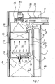
- the fuel-stained heat source 101 shown in its entirety in FIG. 2 has an outer housing 102, which has a rear side 103 and a front side 104, the front side being covered by two doors 105 and 106 arranged one above the other.
- a combustion chamber 108 Arranged in the interior 107 of the outer housing 102 is a combustion chamber 108 which is gas-tight towards the atmosphere and which is connected to the outside atmosphere only via a unit 109 which has a concentric tube.
- the unit 109 has an internal exhaust gas discharge pipe 110 and an external supply air pipe 111, the actual supply air supply having an annular gap which extends between the inner casing of the outer pipe 111 and the outer casing of the inner pipe 110.
- This supply air duct merges into a guide duct 112 which leads vertically downwards on the rear side of the combustion chamber 108 and which opens into the interior 115 of the combustion chamber on the underside 113 in the context of an inlet opening 114.
- a heat exchanger 116 is arranged with a heating shaft 117 extending it toward the rear, the latter both forming the actual interior 115.
- the heat exchanger 116 formed from copper passes through a pipe coil, not shown, which is also wound around the heating shaft 117 on the outside. A fluid to be heated flows through this pipe coil, for example the water from a heating system or sani hot domestic water to be heated.
- an exhaust gas collection chamber 118 On which a fan 119 is arranged, which is driven by a motor 120.
- the exhaust gas outlet of the blower 119 communicates with the interior of the inner tube 110.
- a burner 21 is arranged on the underside 113 of the heating shaft 117 and is fed via a fuel supply line 122 from a gas or oil reservoir, which is not shown in any more detail.
- Below the heating shaft which is covered by the upper door 105 together with the heat exchanger and the exhaust gas hood 118, there is a room 123 in which all measuring, regulating and control instruments of the heat source are accommodated. This space is essentially covered by door 106.
- an expansion vessel 124 is arranged between the rear of the combustion chamber 108 and the rear wall 102 of the housing.
- the rear partition wall 125 of the combustion chamber which also acts as a wall for the guide channel 112 and at the same time is the rear wall of the heating shaft, has a bypass opening 127 in its upper region 126, which is assigned a bypass flap 128.
- the bypass opening 127 connects the beginning of the supply air duct 112 to the interior of the exhaust hood 113, accordingly short-circuits for the actual combustion chamber aar.
- the guide channel 112 is connected in terms of flow to the annular space 129 between the two tubes 110 and 111.
- the passage of the bypass opening 127 is perpendicular to the cross-section of the guide channel 112.
- the two openings thus form an angle of 90 °.
- the bypass flap 128 is designed as a double-arm lever, one lever arm 130 is assigned to the bypass opening 127, the other lever arm 131 to the passage cross section of the guide channel 112.
- the two arms can form a common part which is movable about a pivot axis 132 which is in the region of the rear wall 125 is mounted.
- the two arms 130 and 131 preferably form an obtuse angle.
- This angle is accordingly greater than the angle between the bypass opening and the vertical duct cross section of the guide duct 112. If the bypass flap is formed by two different flap elements, which are mounted to one another and to the housing of the heat source in the context of the axis 132, a spacer 133 is provided which attacks in eyelets 134 and 135 on both flap parts.
- the shaft 132 and the bearing of the two flap elements 136 and 137 which are synonymous with arms 130 and 131, respectively, can be seen in FIG.
- the two flap elements 136 and 137 are provided with teeth, the remaining webs being looped around the axis 132, in each case in the recess of the other flap element.
- the eyelet 135 and the bracket 133 are clearly visible.
- the holder 133 is a curved wire, in which a punched-out tab 135 is suspended.
- a return spring 138 is suspended on one of the two arms 130 or 131 of the exhaust flap, the abutment 139 of which is arranged on the rear wall 103.
- the return spring engages the lever arm 130, specifically at the point 137 at which a rope 140 is likewise fastened.
- the cable 140 is guided and deflected over two rollers 141 and 142, these two rollers having axles fixed to the housing.
- the axis of the roller 14ü lies on a sheet metal bracket 143 on which a further roller 144 is rotatably mounted with its axis.
- the adjusting travel 156 is limited by the adjusting element 156 in accordance with the partial load of the heat source.
- the ratio of the actuator can be changed in relation to the angle of rotation of the flap. It is thus possible to achieve large swivel angles of the bypass flap 128 even with small adjustment paths only available on the actuator 155.
Landscapes
- Engineering & Computer Science (AREA)
- Chemical & Material Sciences (AREA)
- Combustion & Propulsion (AREA)
- Mechanical Engineering (AREA)
- General Engineering & Computer Science (AREA)
- Physics & Mathematics (AREA)
- Thermal Sciences (AREA)
- Housings, Intake/Discharge, And Installation Of Fluid Heaters (AREA)
Applications Claiming Priority (4)
| Application Number | Priority Date | Filing Date | Title |
|---|---|---|---|
| DE8232300U | 1982-11-18 | ||
| DE19828232300 DE8232300U1 (de) | 1982-11-18 | 1982-11-18 | Brennstoffbeheizte waermequelle |
| DE8301955U | 1983-01-22 | ||
| DE19838301955 DE8301955U1 (de) | 1983-01-22 | 1983-01-22 | Brennstoffbeheizte waermequelle |
Publications (2)
| Publication Number | Publication Date |
|---|---|
| EP0109620A2 true EP0109620A2 (fr) | 1984-05-30 |
| EP0109620A3 EP0109620A3 (fr) | 1985-06-26 |
Family
ID=25949352
Family Applications (1)
| Application Number | Title | Priority Date | Filing Date |
|---|---|---|---|
| EP83111256A Withdrawn EP0109620A3 (fr) | 1982-11-18 | 1983-11-11 | Source de chaleur chauffée par combustible |
Country Status (1)
| Country | Link |
|---|---|
| EP (1) | EP0109620A3 (fr) |
Cited By (7)
| Publication number | Priority date | Publication date | Assignee | Title |
|---|---|---|---|---|
| EP0303559A2 (fr) * | 1987-08-13 | 1989-02-15 | Joh. Vaillant GmbH u. Co. | Conduite d'air de combustion au brûleur d'un appareil chauffé par un brûleur, par exemple d'un chauffeur d'eau |
| EP0356690A1 (fr) * | 1988-09-01 | 1990-03-07 | Karl Dungs GmbH & Co. | Producteur de chaleur chauffé au carburant |
| GB2255169A (en) * | 1991-04-27 | 1992-10-28 | Hepworth Heating Ltd | Gas boiler with excess air |
| EP0655579A1 (fr) * | 1993-11-25 | 1995-05-31 | Nefit Fasto B.V. | Brûleur |
| US6612301B2 (en) * | 1999-05-12 | 2003-09-02 | State Industries, Inc. | Water heater |
| EP1434015A2 (fr) * | 2002-12-23 | 2004-06-30 | MERLONI TERMOSANITARI S.p.A. | Chaudière murale universelle, standard à condensation partielle ou totale |
| US7066170B1 (en) | 2000-10-31 | 2006-06-27 | Travis Industries, Inc. | Apparatuses and methods for balancing combustion air and exhaust gas for use with a direct-vent heater appliance |
Citations (3)
| Publication number | Priority date | Publication date | Assignee | Title |
|---|---|---|---|---|
| US4033269A (en) * | 1975-12-24 | 1977-07-05 | Kennecott Copper Corporation | Method and apparatus for controlling gas flow |
| FR2356882A1 (fr) * | 1976-06-28 | 1978-01-27 | Claeys Flandria Nv | Perfectionnements aux procedes et dispositifs pour maintenir pratiquement constant a divers regimes de fonctionnement le rendement d'appareils a evacuation forcee comportant un dispositif de combustion |
| FR2411365A1 (fr) * | 1977-12-07 | 1979-07-06 | Vaillant Sarl | Regulation du debit d'air de combustion |
-
1983
- 1983-11-11 EP EP83111256A patent/EP0109620A3/fr not_active Withdrawn
Patent Citations (3)
| Publication number | Priority date | Publication date | Assignee | Title |
|---|---|---|---|---|
| US4033269A (en) * | 1975-12-24 | 1977-07-05 | Kennecott Copper Corporation | Method and apparatus for controlling gas flow |
| FR2356882A1 (fr) * | 1976-06-28 | 1978-01-27 | Claeys Flandria Nv | Perfectionnements aux procedes et dispositifs pour maintenir pratiquement constant a divers regimes de fonctionnement le rendement d'appareils a evacuation forcee comportant un dispositif de combustion |
| FR2411365A1 (fr) * | 1977-12-07 | 1979-07-06 | Vaillant Sarl | Regulation du debit d'air de combustion |
Cited By (10)
| Publication number | Priority date | Publication date | Assignee | Title |
|---|---|---|---|---|
| EP0303559A2 (fr) * | 1987-08-13 | 1989-02-15 | Joh. Vaillant GmbH u. Co. | Conduite d'air de combustion au brûleur d'un appareil chauffé par un brûleur, par exemple d'un chauffeur d'eau |
| EP0303559A3 (fr) * | 1987-08-13 | 1990-06-20 | Joh. Vaillant GmbH u. Co. | Conduite d'air de combustion au brûleur d'un appareil chauffé par un brûleur, par exemple d'un chauffeur d'eau |
| EP0356690A1 (fr) * | 1988-09-01 | 1990-03-07 | Karl Dungs GmbH & Co. | Producteur de chaleur chauffé au carburant |
| GB2255169A (en) * | 1991-04-27 | 1992-10-28 | Hepworth Heating Ltd | Gas boiler with excess air |
| GB2255169B (en) * | 1991-04-27 | 1994-08-03 | Hepworth Heating Ltd | Gas fired boilers |
| EP0655579A1 (fr) * | 1993-11-25 | 1995-05-31 | Nefit Fasto B.V. | Brûleur |
| US6612301B2 (en) * | 1999-05-12 | 2003-09-02 | State Industries, Inc. | Water heater |
| US7066170B1 (en) | 2000-10-31 | 2006-06-27 | Travis Industries, Inc. | Apparatuses and methods for balancing combustion air and exhaust gas for use with a direct-vent heater appliance |
| EP1434015A2 (fr) * | 2002-12-23 | 2004-06-30 | MERLONI TERMOSANITARI S.p.A. | Chaudière murale universelle, standard à condensation partielle ou totale |
| EP1434015A3 (fr) * | 2002-12-23 | 2004-12-29 | MERLONI TERMOSANITARI S.p.A. | Chaudière murale universelle, standard à condensation partielle ou totale |
Also Published As
| Publication number | Publication date |
|---|---|
| EP0109620A3 (fr) | 1985-06-26 |
Similar Documents
| Publication | Publication Date | Title |
|---|---|---|
| DE3900532A1 (de) | Abgasemission-regelvorrichtung fuer einen dieselmotor | |
| EP0109620A2 (fr) | Source de chaleur chauffée par combustible | |
| WO2012055504A1 (fr) | Dispositif de ventilation muni d'une hotte aspirante | |
| DE2815882A1 (de) | Anlage zum rueckgewinnen von abwaerme | |
| EP1039244B1 (fr) | Dispositif de chauffage avec pile à combustible | |
| DE3340848A1 (de) | Brennstoffbeheizte waermequelle | |
| DE8232300U1 (de) | Brennstoffbeheizte waermequelle | |
| DE3030130A1 (de) | Feuerungsanlage | |
| AT393890B (de) | Vorrichtung zur steuerung des durchsatzes der verbrennungsluft zu einem geblaesebrenner | |
| DE3033624C2 (fr) | ||
| CH665270A5 (de) | Heiz- oder entlueftungsvorrichtung in einem gebaeude. | |
| DE10048454B4 (de) | Regeleinrichtung für das Brennstoff-/Luftverhältnis eines Gebläsebrenners | |
| EP0141944B1 (fr) | Dispositif de réglage de tirage de cheminée | |
| DE3404589A1 (de) | In einem raum aufgestellte waermequelle | |
| DE2166287A1 (de) | Ansaug- und auslasseinheit fuer eine gasbrenneranlage mit fremdzug | |
| DE3234009A1 (de) | An einen kamin angeschlossene waermequelle | |
| DE3345202A1 (de) | Vorrichtung zur herabsetzung der taupunkttemperatur von abgasen | |
| DE925492C (de) | Vorrichtung an Gaswasserheizern zur Abfuehrung der Abgase mittels eines Saugventilators | |
| DE3509570C3 (de) | Brennwert-Heizkessel | |
| DE3306014C2 (fr) | ||
| DE3413743A1 (de) | Vorrichtung zur dekontamination von gegenstaenden, insbesondere bekleidungsstuecken | |
| DE2433387C3 (de) | Einrichtung zur Zweitluftzufuhr zur Feuerung von Dampferzeugern | |
| DE3323319C2 (fr) | ||
| DE3023268C2 (de) | Lüftungsvorrichtung für Werkshallen | |
| AT359695B (de) | Vorrichtung zum ausnuetzen der abwaerme von rauchgasen, insbesondere bei ofenheizungen |
Legal Events
| Date | Code | Title | Description |
|---|---|---|---|
| PUAI | Public reference made under article 153(3) epc to a published international application that has entered the european phase |
Free format text: ORIGINAL CODE: 0009012 |
|
| AK | Designated contracting states |
Designated state(s): AT BE CH DE FR GB IT LI LU NL SE |
|
| PUAL | Search report despatched |
Free format text: ORIGINAL CODE: 0009013 |
|
| RHK1 | Main classification (correction) |
Ipc: F23L 3/00 |
|
| AK | Designated contracting states |
Designated state(s): AT BE CH DE FR GB IT LI LU NL SE |
|
| 17P | Request for examination filed |
Effective date: 19851030 |
|
| 17Q | First examination report despatched |
Effective date: 19860829 |
|
| R17C | First examination report despatched (corrected) |
Effective date: 19870702 |
|
| STAA | Information on the status of an ep patent application or granted ep patent |
Free format text: STATUS: THE APPLICATION HAS BEEN WITHDRAWN |
|
| 18W | Application withdrawn |
Withdrawal date: 19871111 |
|
| RIN1 | Information on inventor provided before grant (corrected) |
Inventor name: FRIEDRICH, PETER Inventor name: PELZER, KURT |