EP0109570B1 - Dispositif pour tester des débitmètres - Google Patents
Dispositif pour tester des débitmètres Download PDFInfo
- Publication number
- EP0109570B1 EP0109570B1 EP83110529A EP83110529A EP0109570B1 EP 0109570 B1 EP0109570 B1 EP 0109570B1 EP 83110529 A EP83110529 A EP 83110529A EP 83110529 A EP83110529 A EP 83110529A EP 0109570 B1 EP0109570 B1 EP 0109570B1
- Authority
- EP
- European Patent Office
- Prior art keywords
- mensuration
- section
- measuring
- pipe
- valve
- Prior art date
- Legal status (The legal status is an assumption and is not a legal conclusion. Google has not performed a legal analysis and makes no representation as to the accuracy of the status listed.)
- Expired
Links
- 239000012530 fluid Substances 0.000 claims abstract 3
- 238000013016 damping Methods 0.000 claims description 4
- 238000006073 displacement reaction Methods 0.000 abstract description 2
- 239000007788 liquid Substances 0.000 description 20
- 238000000034 method Methods 0.000 description 5
- 238000009434 installation Methods 0.000 description 3
- 238000005259 measurement Methods 0.000 description 3
- 239000000523 sample Substances 0.000 description 2
- 238000010276 construction Methods 0.000 description 1
- 230000000630 rising effect Effects 0.000 description 1
- 238000007789 sealing Methods 0.000 description 1
Images
Classifications
-
- G—PHYSICS
- G01—MEASURING; TESTING
- G01F—MEASURING VOLUME, VOLUME FLOW, MASS FLOW OR LIQUID LEVEL; METERING BY VOLUME
- G01F25/00—Testing or calibration of apparatus for measuring volume, volume flow or liquid level or for metering by volume
- G01F25/10—Testing or calibration of apparatus for measuring volume, volume flow or liquid level or for metering by volume of flowmeters
- G01F25/11—Testing or calibration of apparatus for measuring volume, volume flow or liquid level or for metering by volume of flowmeters using a seal ball or piston in a test loop
Definitions
- the invention relates to a test device for a flow meter permanently installed in a pipeline, in particular for higher media pressures, in which a cylindrical calibration container installed in a bypass line of the pipeline and which can be optionally switched into the pipeline in series with the flow meter at the beginning and on End of a measuring section carries a start or stop switch, by means of which, when a measuring piston slides past in the calibration container and is displaced by the liquid to be measured, the addition of electrical pulses of the flow meter is started and stopped again, the added pulses with the calibration volume of the measuring section to be related.
- DE-A-12 49 547 describes a test device according to the above-mentioned type.
- the valve device for diverting the liquid flowing in the pipeline into the calibration container installed in the bypass line consists of several in front of and behind the calibration container in the bypass line and several shut-off or changeover valves installed in the pipeline, which makes the test device very complex to construct and requires a relatively large amount of time for switching the medium flow to the calibration container.
- the measuring section is located in the one embodiment in a long lying measuring tube in which a measuring piston displaced by the liquid to be measured slides from one end position to the other end position and actuates the start switch and the stop switch as it moves past.
- the measuring section is formed by a standing calibration container, in which a start probe and a stop probe respond to the rising liquid level in the calibration container.
- a start probe and a stop probe respond to the rising liquid level in the calibration container.
- a test device for Du ⁇ chflußmesser in which the measuring section is in a long lying measuring tube, which is surrounded by an outer tube, so that in the measuring tube receiving the measuring tube does not pose the danger due to the pressure compensation there is an expansion.
- the annular space between the measuring tube and the outer tube is designed here as a supply and discharge chamber for the measuring liquid and is installed directly in the pipeline, so that this annular space and the measuring cylinder are constantly flowed through by the liquid flowing in the pipeline. Since the test facility is not installed in a bypass line of the pipeline but sits directly in the pipeline, the test facility cannot be switched off during the long test breaks. As a result of the numerous deflections, there is also a considerable loss of pressure when the test device is constantly flowing through, and pressure surges cannot be avoided when the flow direction in the measuring tube is reversed via the rotary valve provided for this purpose.
- the object of the invention is to design the test device installed in a bypass line of the pipeline in such a way that the switching of the liquid flow to be measured from the pipeline to the bypass line and vice versa takes place quickly and safely with the least structural means and a high level with the test device with the simplest construction Measurement accuracy is achieved and that measurement errors are avoided even at higher media pressures.
- valve device consists of only a single shut-off valve, which is installed in the pipeline between the two connections of the bypass line, the switching of the liquid flow to be measured from the pipeline to the calibration container installed in the bypass line, which is necessary for the test process, can be carried out with the least structural means and done in a very short time just by operating this one valve. Due to the vertical arrangement of the calibration container and the measuring piston sliding in the measuring cylinder jacket, the liquid flow can only flow again through the pipeline when the valve is opened, since the measuring piston sliding in the measuring cylinder jacket of the calibration container then automatically returns to its starting position by its own weight and / or by the differential pressure device and the bypass line is automatically blocked.
- the measuring cylinder jacket in the calibration container is relieved of pressure, so that an expansion of the measuring cylinder jacket and thus an increase in the measuring volume is avoided even at high line pressures, and a jamming-free easy return of the measuring piston to the starting position solely by the Dead weight of the volumetric flask or with the support of a differential pressure device is achieved.
- a particularly expedient installation of the measuring cylinder jacket in the calibration container results from the features of claim 2, wherein the sealing of the inlet end of the measuring cylinder jacket to the pressure chamber of the calibration container ensures that the entire flowing into the bypass line The amount of liquid also passes through the measuring cylinder jacket and thus acts on the measuring piston in the displacing sense in the area of the measuring section.
- the pressure compensation of the measuring cylinder jacket is made possible in a simple manner and the liquid flow can pass the calibration container and the bypass line in the shortest possible way and thus in a flow-efficient manner.
- the measuring cylinder jacket which in a manner known per se has a measuring section located between the start and stop switch as well as a start-up section and a follow-up section, has jacket openings according to the feature of claim 3 in the area of the follow-up section through which the liquid displaced by the measuring piston flows through the measuring cylinder jacket can flow directly to the side into the pressure equalization chamber and from here into the bypass line, so that a sufficiently high liquid throughput is ensured.
- the measuring cylinder jacket is provided according to claim 4 at the outlet end with an inwardly projecting stroke limiting edge, whereby a stop for the measuring piston is formed in a simple manner.
- the container lid has a damping spring for the volumetric piston, then the movement of the volumetric piston is effectively braked shortly before it hits the stroke limiting edge.
- a reliable automatic return of the volumetric flask to the starting position is achieved according to the feature of claim 6 by a venturi tube-like narrowing of the pipeline, which is provided in the connection area of the inlet section of the bypass line.
- a venturi tube-like narrowing of the pipeline which is provided in the connection area of the inlet section of the bypass line.
- the length of the starting section of the measuring cylinder jacket is matched to the closing time of the shut-off valve according to claim 7, it is ensured that the start switch is only run over by the measuring piston when the direct passage through the pipeline is absolutely blocked.
- the start of the measuring cylinder can be shortened in that the shut-off valve is designed as a quick-closing valve.
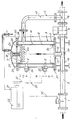
- the flow meter 1 to be tested is permanently installed in the pipeline 2 through which the medium to be measured flows.
- the test device for the flow meter 1 consists of a cylindrical calibration container 4 installed vertically in a bypass line 3 of the pipe 2, through which the liquid flowing in the pipe 2 flows from bottom to top after the shut-off valve 5 is closed, and thereby in series with the flow meter 1 is switchable.
- the calibration container 4 carries in its interior a measuring cylinder jacket 6 in which the measuring piston 7 slides.
- the measuring cylinder jacket 6 contains the measuring section 10 lying between the start position 8 and the stop position with the calibration volume to be displaced.
- the measuring section 10 is preceded by the starting section 11 in the measuring cylinder jacket 6, and the following section 12 is provided behind the measuring section 10 for the measuring piston 7.
- the pressure compensation chamber 14 is located between the jacket 13 of the calibration container 4 and the measuring cylinder jacket 6.
- the inlet section 15 of the bypass pipe is connected to a flanged pipe section 16, and the outlet section 17 of the bypass pipe 3 is flanged to the branch pipe section 18.
- the shut-off valve 5 is clamped with its flanges between the pipe section 16 and the branch pipe section 18, so that for the test device there is a connecting section formed from the three pipe sections 16, 5 and 18 connected in series for installation in the pipeline 2.
- the inlet section 15 of the bypass line 3 sits firmly on the bottom 19 of the calibration container 4 and opens freely from below into the measuring cylinder jacket 6, the lower edge of which is tightly connected at the connection point 20 to the bottom flange 21 of the container jacket 13.
- the measuring cylinder jacket 6 has jacket openings 22 distributed over the circumference, through which the liquid displaced by the measuring piston 7 can flow laterally into the pressure compensation chamber 14 and from there via the outlet section 17 of the bypass line 3 connected to the pressure compensation chamber 14.
- the liquid also emerges from the top of the measuring cylinder jacket 6, whereby it is deflected downwards on the curved container cover 23 and flows through the openings 24 in the cover flange 25 and in the upper container flange 26 into the pressure compensation chamber 14 and further into the outlet section 17 of the bypass line 3.
- the measuring cylinder jacket 6 is held concentrically at the connection point 27 by the upper container flange 26 and below at the connection point 20 by the lower container flange 21, it being possible for an elastic intermediate member to be inserted at the connection points 20 and 27 between the measuring cylinder jacket 6 and the two container flanges 21 and 26 , so that a possible expansion of the Calibration container 4 is not transferred to the measuring cylinder jacket 6.
- the cover flange 25 of the container cover 23 engages over the measuring cylinder jacket 6 inwards, as a result of which a stroke limiting edge 28 is formed for the measuring piston 7. So that a soft placement of the measuring piston 7 on the stroke limiting edge 28 is ensured, a damping spring 29 is also installed in the container lid 23.
- the pipe section 16 inserted into the pipe 2 is provided in the region of the branching point of the inlet section 15 of the bypass pipe with a venturi-like constriction 30, which forms the differential pressure device for returning the measuring piston 7 to the starting position.
- the mode of operation of the test device is as follows: Before the test process begins, the shut-off valve 5 is opened so that the liquid flows straight through the pipeline 2. The measuring piston 7 is still in the lower starting position shown by dotted lines, which it has assumed automatically due to its own weight and due to the backflow occurring in the bypass line 3 as a result of the pressure difference generated at the constriction 30. The measuring piston 7 shuts off the flow through the bypass line 3. For the test process, the closing process of the shut-off valve 5 is initiated via the control line 31 from the evaluator 32, so that when the valve is in the closed position, the entire liquid passing through the flow meter 8 flows through the bypass line 3 and through the calibration container 4.
- the liquid enters the measuring cylinder jacket 6 via the inlet section 15 and displaces the measuring piston 7 in the area of the starting section 11 up to the starting position 8.
- the shut-off valve 5 must have been moved into the closing end position.
- the start switch 33 responds and the control line 34 triggers the addition of the flow pulses coming from the flow meter 8 via the pulse line 35 in the evaluator 32.
- the measuring piston 7 After passing through the measuring section 10, d. H. after displacement of the container calibration volume, the measuring piston 7 reaches the stop position 9, in which the stop switch 36 interrupts the addition of the flow impulses coming from the flow meter 8 in the evaluator 32 via the control line 37. At the same time, the opening of the shut-off valve 5 is automatically initiated by the evaluator 32 via the control line 31. During the valve opening process, the measuring piston 7 is displaced further upward over the area of the trailing section 12, the piston movement being damped when the jacket openings 22 of the measuring cylinder jacket 6 are passed over because of the smaller outflow cross sections of the cover openings 24. Before hitting the stroke limiting edge 28, the measuring piston 7 is braked softly by the damping spring 29.
- the amount of liquid resulting from the added flow impulses of the flow meter 8 to be tested is compared with the displaced calibration volume of the measuring section 10 and the measuring error is displayed.
- the shut-off valve 5 When the shut-off valve 5 is fully open, the flow again takes place in a straight line through the installation section 16, 5 and 18 of the pipeline 2 and the volumetric piston 7 slowly moves back into the lower starting position due to its own weight, the venturi-like constriction 30 triggering a backflow in the bypass line 3 due to the pressure difference , which supports the return movement of the volumetric piston 7 considerably.
- the shut-off valve 5 is designed as a quick-closing valve so that the length of the run-up section 11 and the run-out section 12 can be kept as short as possible.
Landscapes
- Physics & Mathematics (AREA)
- Fluid Mechanics (AREA)
- General Physics & Mathematics (AREA)
- Measuring Volume Flow (AREA)
Claims (8)
Priority Applications (1)
| Application Number | Priority Date | Filing Date | Title |
|---|---|---|---|
| AT83110529T ATE28105T1 (de) | 1982-10-23 | 1983-10-22 | Pruefeinrichtung fuer durchflussmesser. |
Applications Claiming Priority (2)
| Application Number | Priority Date | Filing Date | Title |
|---|---|---|---|
| DE3239281A DE3239281C2 (de) | 1982-10-23 | 1982-10-23 | Prüfeinrichtung für Durchflußmesser |
| DE3239281 | 1982-10-23 |
Publications (3)
| Publication Number | Publication Date |
|---|---|
| EP0109570A2 EP0109570A2 (fr) | 1984-05-30 |
| EP0109570A3 EP0109570A3 (en) | 1984-07-18 |
| EP0109570B1 true EP0109570B1 (fr) | 1987-07-01 |
Family
ID=6176427
Family Applications (1)
| Application Number | Title | Priority Date | Filing Date |
|---|---|---|---|
| EP83110529A Expired EP0109570B1 (fr) | 1982-10-23 | 1983-10-22 | Dispositif pour tester des débitmètres |
Country Status (4)
| Country | Link |
|---|---|
| US (1) | US4517823A (fr) |
| EP (1) | EP0109570B1 (fr) |
| AT (1) | ATE28105T1 (fr) |
| DE (1) | DE3239281C2 (fr) |
Families Citing this family (10)
| Publication number | Priority date | Publication date | Assignee | Title |
|---|---|---|---|---|
| US4718267A (en) * | 1986-08-18 | 1988-01-12 | Graham Capper | Meter provers |
| GB9204065D0 (en) * | 1992-02-26 | 1992-04-08 | British Petroleum Co Plc | Improvements relating to flow measurement |
| CA2097255A1 (fr) * | 1993-05-28 | 1994-11-29 | Neat Tuot | Appareil d'essai et d'etalonnage automatique pour instruments et debitmetres |
| DE29910635U1 (de) | 1999-06-18 | 2000-01-13 | Virotec Rohrtechnik GmbH & Co. KG, 63571 Gelnhausen | Prüfeinrichtung für einen Strömungsmelder |
| DE19947992C2 (de) * | 1999-10-06 | 2003-03-13 | Alfred Schoepf | Verfahren und Messanlage zur Überprüfung eines Durchflussmessers im eingebauten Zustand |
| CA2511824A1 (fr) | 2002-12-26 | 2004-07-22 | Syngenta Participations Ag | Polypeptides associes a la proliferation cellulaire et leurs utilisations |
| RU2241962C1 (ru) * | 2003-11-27 | 2004-12-10 | Закрытое акционерное общество "Взлет" | Устройство для поверки расходомеров |
| DE102005005437A1 (de) * | 2005-02-05 | 2006-08-10 | Eppendorf Ag | Filterpipettenspitze |
| US20080302986A1 (en) * | 2007-06-11 | 2008-12-11 | Leahy Rick E | Method and apparatus for injecting additives and for safely calibrating accuracy of a flow meter in a closed system |
| DE102010014693B3 (de) * | 2010-04-12 | 2011-11-17 | Bundesrepublik Deutschland, vertr.d.d. Bundesministerium für Wirtschaft und Technologie, d.vertr.d.d. Präsidenten der Physikalisch-Technischen Bundesanstalt | Fluid-Durchflussmesssystem, Kalibriervorrichtung für ein Fluid-Durchflussmesssystem und Verfahren zum Kalibrieren eines Durchflussmessgerätes |
Family Cites Families (6)
| Publication number | Priority date | Publication date | Assignee | Title |
|---|---|---|---|---|
| DE1249547B (fr) * | 1967-09-07 | |||
| US3273375A (en) * | 1964-11-24 | 1966-09-20 | Halmor Ind Inc | Flow meter calibrating barrel |
| US3492856A (en) * | 1968-09-06 | 1970-02-03 | Flow Tech | Apparatus for determining the flow characteristics of a volumetric flowmeter |
| US4152922A (en) * | 1978-05-19 | 1979-05-08 | Flow Technology, Inc. | Apparatus and method for determining the characteristic of a flowmeter |
| FR2468890A1 (fr) * | 1979-11-05 | 1981-05-08 | Mestrole Mesure Controle Autom | Jauge d'etalonnage |
| US4372147A (en) * | 1981-03-17 | 1983-02-08 | Waugh Controls Corporation | Flow meter prover apparatus and method |
-
1982
- 1982-10-23 DE DE3239281A patent/DE3239281C2/de not_active Expired
-
1983
- 1983-02-07 US US06/464,737 patent/US4517823A/en not_active Expired - Fee Related
- 1983-10-22 EP EP83110529A patent/EP0109570B1/fr not_active Expired
- 1983-10-22 AT AT83110529T patent/ATE28105T1/de not_active IP Right Cessation
Also Published As
| Publication number | Publication date |
|---|---|
| ATE28105T1 (de) | 1987-07-15 |
| DE3239281C2 (de) | 1984-11-08 |
| US4517823A (en) | 1985-05-21 |
| EP0109570A3 (en) | 1984-07-18 |
| DE3239281A1 (de) | 1984-04-26 |
| EP0109570A2 (fr) | 1984-05-30 |
Similar Documents
| Publication | Publication Date | Title |
|---|---|---|
| EP0109570B1 (fr) | Dispositif pour tester des débitmètres | |
| DE2918051C2 (de) | Prüfeinrichtung für in einem Fluid-Betriebssystem angeordnete, volumetrische Strömungsmesser | |
| DE3347695C2 (de) | Prüfeinrichtung für Durchflußmesser | |
| EP1935322A2 (fr) | Lave-vaisselle | |
| DE102013008781B4 (de) | Ultraschalldurchflusszähler | |
| US3978707A (en) | Flow control apparatus and system | |
| DE3732703A1 (de) | Verbundwasserzaehler | |
| DE102011101087A1 (de) | Steuereinrichtung einer Ausbaueinheit im Streb eines Bergwerks | |
| DE2262699A1 (de) | Leckanzeigevorrichtung | |
| DE2703096A1 (de) | Vorrichtung zum messen einer brennstoffmenge | |
| DE1073825B (de) | Stellungsanzeiger für ferngesteuerte Ventile u. dgl | |
| DE8229791U1 (de) | Pruefeinrichtung fuer durchflussmesser | |
| DE7213157U (de) | Rückflußverhinderer mit waagerechtem Durchgang für in Rohrleitungen eingebaute Wasserzähler | |
| DE102017001315A1 (de) | Adaptierbarer Nebenzähler für einen Verbundzähler zur Durchflussbestimmung eines strömenden Mediums | |
| DE3841372C1 (fr) | ||
| DE2360299A1 (de) | Verfahren und vorrichtung zum automatischen dosieren von vorgegebenen fluessigkeitsmengen | |
| DE2360274A1 (de) | Zulaufschlauch mit selbstschliessendem sicherheitsventil | |
| DE3316205C2 (fr) | ||
| DE1498379B1 (de) | Durchflusssystem mit einem Gasabscheider | |
| DE4232774A1 (de) | Verbundwasserzähler | |
| DE1773073A1 (de) | Wirkdruckgeber | |
| DE427467C (de) | Dampfwasserableiter mit Bewegung des Ablassorgans durch Kippgefaesse | |
| DE833861C (de) | Gasdruckwellendaempfer | |
| DE662037C (de) | Fluessigkeitsmengenmesser | |
| DE1932204C3 (de) | Schraubspindel-Entlüftungsventil für Flüssigkeits-Differenzdruckmanometer |
Legal Events
| Date | Code | Title | Description |
|---|---|---|---|
| PUAI | Public reference made under article 153(3) epc to a published international application that has entered the european phase |
Free format text: ORIGINAL CODE: 0009012 |
|
| PUAL | Search report despatched |
Free format text: ORIGINAL CODE: 0009013 |
|
| AK | Designated contracting states |
Designated state(s): AT FR GB IT NL |
|
| AK | Designated contracting states |
Designated state(s): AT FR GB IT NL |
|
| 17P | Request for examination filed |
Effective date: 19841228 |
|
| GRAA | (expected) grant |
Free format text: ORIGINAL CODE: 0009210 |
|
| AK | Designated contracting states |
Kind code of ref document: B1 Designated state(s): AT FR GB IT NL |
|
| REF | Corresponds to: |
Ref document number: 28105 Country of ref document: AT Date of ref document: 19870715 Kind code of ref document: T |
|
| ITF | It: translation for a ep patent filed | ||
| ET | Fr: translation filed | ||
| PLBE | No opposition filed within time limit |
Free format text: ORIGINAL CODE: 0009261 |
|
| STAA | Information on the status of an ep patent application or granted ep patent |
Free format text: STATUS: NO OPPOSITION FILED WITHIN TIME LIMIT |
|
| 26N | No opposition filed | ||
| NLS | Nl: assignments of ep-patents |
Owner name: BOPP & REUTHER AKTIENGESELLSCHAFT TE MANNHEIM, BON |
|
| PGFP | Annual fee paid to national office [announced via postgrant information from national office to epo] |
Ref country code: GB Payment date: 19911021 Year of fee payment: 9 |
|
| PGFP | Annual fee paid to national office [announced via postgrant information from national office to epo] |
Ref country code: AT Payment date: 19911030 Year of fee payment: 9 |
|
| ITTA | It: last paid annual fee | ||
| PGFP | Annual fee paid to national office [announced via postgrant information from national office to epo] |
Ref country code: NL Payment date: 19911031 Year of fee payment: 9 |
|
| PG25 | Lapsed in a contracting state [announced via postgrant information from national office to epo] |
Ref country code: GB Effective date: 19921022 Ref country code: AT Effective date: 19921022 |
|
| PGFP | Annual fee paid to national office [announced via postgrant information from national office to epo] |
Ref country code: FR Payment date: 19921026 Year of fee payment: 10 |
|
| PG25 | Lapsed in a contracting state [announced via postgrant information from national office to epo] |
Ref country code: NL Effective date: 19930501 |
|
| GBPC | Gb: european patent ceased through non-payment of renewal fee |
Effective date: 19921022 |
|
| NLV4 | Nl: lapsed or anulled due to non-payment of the annual fee | ||
| PG25 | Lapsed in a contracting state [announced via postgrant information from national office to epo] |
Ref country code: FR Effective date: 19940630 |
|
| REG | Reference to a national code |
Ref country code: FR Ref legal event code: ST |