EP0109570B1 - Device for testing flow meters - Google Patents
Device for testing flow meters Download PDFInfo
- Publication number
- EP0109570B1 EP0109570B1 EP83110529A EP83110529A EP0109570B1 EP 0109570 B1 EP0109570 B1 EP 0109570B1 EP 83110529 A EP83110529 A EP 83110529A EP 83110529 A EP83110529 A EP 83110529A EP 0109570 B1 EP0109570 B1 EP 0109570B1
- Authority
- EP
- European Patent Office
- Prior art keywords
- mensuration
- section
- measuring
- pipe
- valve
- Prior art date
- Legal status (The legal status is an assumption and is not a legal conclusion. Google has not performed a legal analysis and makes no representation as to the accuracy of the status listed.)
- Expired
Links
- 239000012530 fluid Substances 0.000 claims abstract 3
- 238000013016 damping Methods 0.000 claims description 4
- 238000006073 displacement reaction Methods 0.000 abstract description 2
- 239000007788 liquid Substances 0.000 description 20
- 238000000034 method Methods 0.000 description 5
- 238000009434 installation Methods 0.000 description 3
- 238000005259 measurement Methods 0.000 description 3
- 239000000523 sample Substances 0.000 description 2
- 238000010276 construction Methods 0.000 description 1
- 230000000630 rising effect Effects 0.000 description 1
- 238000007789 sealing Methods 0.000 description 1
Images
Classifications
-
- G—PHYSICS
- G01—MEASURING; TESTING
- G01F—MEASURING VOLUME, VOLUME FLOW, MASS FLOW OR LIQUID LEVEL; METERING BY VOLUME
- G01F25/00—Testing or calibration of apparatus for measuring volume, volume flow or liquid level or for metering by volume
- G01F25/10—Testing or calibration of apparatus for measuring volume, volume flow or liquid level or for metering by volume of flowmeters
- G01F25/11—Testing or calibration of apparatus for measuring volume, volume flow or liquid level or for metering by volume of flowmeters using a seal ball or piston in a test loop
Definitions
- the invention relates to a test device for a flow meter permanently installed in a pipeline, in particular for higher media pressures, in which a cylindrical calibration container installed in a bypass line of the pipeline and which can be optionally switched into the pipeline in series with the flow meter at the beginning and on End of a measuring section carries a start or stop switch, by means of which, when a measuring piston slides past in the calibration container and is displaced by the liquid to be measured, the addition of electrical pulses of the flow meter is started and stopped again, the added pulses with the calibration volume of the measuring section to be related.
- DE-A-12 49 547 describes a test device according to the above-mentioned type.
- the valve device for diverting the liquid flowing in the pipeline into the calibration container installed in the bypass line consists of several in front of and behind the calibration container in the bypass line and several shut-off or changeover valves installed in the pipeline, which makes the test device very complex to construct and requires a relatively large amount of time for switching the medium flow to the calibration container.
- the measuring section is located in the one embodiment in a long lying measuring tube in which a measuring piston displaced by the liquid to be measured slides from one end position to the other end position and actuates the start switch and the stop switch as it moves past.
- the measuring section is formed by a standing calibration container, in which a start probe and a stop probe respond to the rising liquid level in the calibration container.
- a start probe and a stop probe respond to the rising liquid level in the calibration container.
- a test device for Du ⁇ chflußmesser in which the measuring section is in a long lying measuring tube, which is surrounded by an outer tube, so that in the measuring tube receiving the measuring tube does not pose the danger due to the pressure compensation there is an expansion.
- the annular space between the measuring tube and the outer tube is designed here as a supply and discharge chamber for the measuring liquid and is installed directly in the pipeline, so that this annular space and the measuring cylinder are constantly flowed through by the liquid flowing in the pipeline. Since the test facility is not installed in a bypass line of the pipeline but sits directly in the pipeline, the test facility cannot be switched off during the long test breaks. As a result of the numerous deflections, there is also a considerable loss of pressure when the test device is constantly flowing through, and pressure surges cannot be avoided when the flow direction in the measuring tube is reversed via the rotary valve provided for this purpose.
- the object of the invention is to design the test device installed in a bypass line of the pipeline in such a way that the switching of the liquid flow to be measured from the pipeline to the bypass line and vice versa takes place quickly and safely with the least structural means and a high level with the test device with the simplest construction Measurement accuracy is achieved and that measurement errors are avoided even at higher media pressures.
- valve device consists of only a single shut-off valve, which is installed in the pipeline between the two connections of the bypass line, the switching of the liquid flow to be measured from the pipeline to the calibration container installed in the bypass line, which is necessary for the test process, can be carried out with the least structural means and done in a very short time just by operating this one valve. Due to the vertical arrangement of the calibration container and the measuring piston sliding in the measuring cylinder jacket, the liquid flow can only flow again through the pipeline when the valve is opened, since the measuring piston sliding in the measuring cylinder jacket of the calibration container then automatically returns to its starting position by its own weight and / or by the differential pressure device and the bypass line is automatically blocked.
- the measuring cylinder jacket in the calibration container is relieved of pressure, so that an expansion of the measuring cylinder jacket and thus an increase in the measuring volume is avoided even at high line pressures, and a jamming-free easy return of the measuring piston to the starting position solely by the Dead weight of the volumetric flask or with the support of a differential pressure device is achieved.
- a particularly expedient installation of the measuring cylinder jacket in the calibration container results from the features of claim 2, wherein the sealing of the inlet end of the measuring cylinder jacket to the pressure chamber of the calibration container ensures that the entire flowing into the bypass line The amount of liquid also passes through the measuring cylinder jacket and thus acts on the measuring piston in the displacing sense in the area of the measuring section.
- the pressure compensation of the measuring cylinder jacket is made possible in a simple manner and the liquid flow can pass the calibration container and the bypass line in the shortest possible way and thus in a flow-efficient manner.
- the measuring cylinder jacket which in a manner known per se has a measuring section located between the start and stop switch as well as a start-up section and a follow-up section, has jacket openings according to the feature of claim 3 in the area of the follow-up section through which the liquid displaced by the measuring piston flows through the measuring cylinder jacket can flow directly to the side into the pressure equalization chamber and from here into the bypass line, so that a sufficiently high liquid throughput is ensured.
- the measuring cylinder jacket is provided according to claim 4 at the outlet end with an inwardly projecting stroke limiting edge, whereby a stop for the measuring piston is formed in a simple manner.
- the container lid has a damping spring for the volumetric piston, then the movement of the volumetric piston is effectively braked shortly before it hits the stroke limiting edge.
- a reliable automatic return of the volumetric flask to the starting position is achieved according to the feature of claim 6 by a venturi tube-like narrowing of the pipeline, which is provided in the connection area of the inlet section of the bypass line.
- a venturi tube-like narrowing of the pipeline which is provided in the connection area of the inlet section of the bypass line.
- the length of the starting section of the measuring cylinder jacket is matched to the closing time of the shut-off valve according to claim 7, it is ensured that the start switch is only run over by the measuring piston when the direct passage through the pipeline is absolutely blocked.
- the start of the measuring cylinder can be shortened in that the shut-off valve is designed as a quick-closing valve.
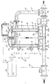
- the flow meter 1 to be tested is permanently installed in the pipeline 2 through which the medium to be measured flows.
- the test device for the flow meter 1 consists of a cylindrical calibration container 4 installed vertically in a bypass line 3 of the pipe 2, through which the liquid flowing in the pipe 2 flows from bottom to top after the shut-off valve 5 is closed, and thereby in series with the flow meter 1 is switchable.
- the calibration container 4 carries in its interior a measuring cylinder jacket 6 in which the measuring piston 7 slides.
- the measuring cylinder jacket 6 contains the measuring section 10 lying between the start position 8 and the stop position with the calibration volume to be displaced.
- the measuring section 10 is preceded by the starting section 11 in the measuring cylinder jacket 6, and the following section 12 is provided behind the measuring section 10 for the measuring piston 7.
- the pressure compensation chamber 14 is located between the jacket 13 of the calibration container 4 and the measuring cylinder jacket 6.
- the inlet section 15 of the bypass pipe is connected to a flanged pipe section 16, and the outlet section 17 of the bypass pipe 3 is flanged to the branch pipe section 18.
- the shut-off valve 5 is clamped with its flanges between the pipe section 16 and the branch pipe section 18, so that for the test device there is a connecting section formed from the three pipe sections 16, 5 and 18 connected in series for installation in the pipeline 2.
- the inlet section 15 of the bypass line 3 sits firmly on the bottom 19 of the calibration container 4 and opens freely from below into the measuring cylinder jacket 6, the lower edge of which is tightly connected at the connection point 20 to the bottom flange 21 of the container jacket 13.
- the measuring cylinder jacket 6 has jacket openings 22 distributed over the circumference, through which the liquid displaced by the measuring piston 7 can flow laterally into the pressure compensation chamber 14 and from there via the outlet section 17 of the bypass line 3 connected to the pressure compensation chamber 14.
- the liquid also emerges from the top of the measuring cylinder jacket 6, whereby it is deflected downwards on the curved container cover 23 and flows through the openings 24 in the cover flange 25 and in the upper container flange 26 into the pressure compensation chamber 14 and further into the outlet section 17 of the bypass line 3.
- the measuring cylinder jacket 6 is held concentrically at the connection point 27 by the upper container flange 26 and below at the connection point 20 by the lower container flange 21, it being possible for an elastic intermediate member to be inserted at the connection points 20 and 27 between the measuring cylinder jacket 6 and the two container flanges 21 and 26 , so that a possible expansion of the Calibration container 4 is not transferred to the measuring cylinder jacket 6.
- the cover flange 25 of the container cover 23 engages over the measuring cylinder jacket 6 inwards, as a result of which a stroke limiting edge 28 is formed for the measuring piston 7. So that a soft placement of the measuring piston 7 on the stroke limiting edge 28 is ensured, a damping spring 29 is also installed in the container lid 23.
- the pipe section 16 inserted into the pipe 2 is provided in the region of the branching point of the inlet section 15 of the bypass pipe with a venturi-like constriction 30, which forms the differential pressure device for returning the measuring piston 7 to the starting position.
- the mode of operation of the test device is as follows: Before the test process begins, the shut-off valve 5 is opened so that the liquid flows straight through the pipeline 2. The measuring piston 7 is still in the lower starting position shown by dotted lines, which it has assumed automatically due to its own weight and due to the backflow occurring in the bypass line 3 as a result of the pressure difference generated at the constriction 30. The measuring piston 7 shuts off the flow through the bypass line 3. For the test process, the closing process of the shut-off valve 5 is initiated via the control line 31 from the evaluator 32, so that when the valve is in the closed position, the entire liquid passing through the flow meter 8 flows through the bypass line 3 and through the calibration container 4.
- the liquid enters the measuring cylinder jacket 6 via the inlet section 15 and displaces the measuring piston 7 in the area of the starting section 11 up to the starting position 8.
- the shut-off valve 5 must have been moved into the closing end position.
- the start switch 33 responds and the control line 34 triggers the addition of the flow pulses coming from the flow meter 8 via the pulse line 35 in the evaluator 32.
- the measuring piston 7 After passing through the measuring section 10, d. H. after displacement of the container calibration volume, the measuring piston 7 reaches the stop position 9, in which the stop switch 36 interrupts the addition of the flow impulses coming from the flow meter 8 in the evaluator 32 via the control line 37. At the same time, the opening of the shut-off valve 5 is automatically initiated by the evaluator 32 via the control line 31. During the valve opening process, the measuring piston 7 is displaced further upward over the area of the trailing section 12, the piston movement being damped when the jacket openings 22 of the measuring cylinder jacket 6 are passed over because of the smaller outflow cross sections of the cover openings 24. Before hitting the stroke limiting edge 28, the measuring piston 7 is braked softly by the damping spring 29.
- the amount of liquid resulting from the added flow impulses of the flow meter 8 to be tested is compared with the displaced calibration volume of the measuring section 10 and the measuring error is displayed.
- the shut-off valve 5 When the shut-off valve 5 is fully open, the flow again takes place in a straight line through the installation section 16, 5 and 18 of the pipeline 2 and the volumetric piston 7 slowly moves back into the lower starting position due to its own weight, the venturi-like constriction 30 triggering a backflow in the bypass line 3 due to the pressure difference , which supports the return movement of the volumetric piston 7 considerably.
- the shut-off valve 5 is designed as a quick-closing valve so that the length of the run-up section 11 and the run-out section 12 can be kept as short as possible.
Landscapes
- Physics & Mathematics (AREA)
- Fluid Mechanics (AREA)
- General Physics & Mathematics (AREA)
- Measuring Volume Flow (AREA)
Abstract
Description
Die Erfindung bezieht sich auf eine Prüfeinrichtung für einen fest in eine Rohrleitung eingebauten Durchflußmesser, insbesondere für höhere Mediendrücke, bei der ein in einer Bypassleitung der Rohrleitung eingebauter und durch eine Ventilanordnung wahlweise in die Rohrleitung in Reihe mit dem Durchflußmesser einschaltbarer zylindrischer Eichbehälter am Beging und am Ende einer Meßstrecke einen Start- bzw. Stoppschalter trägt, durch die beim Vorbeibewegen eines in dem Eichbehälter gleitenden und von der zu messenden Flüssigkeit verdrängten Meßkolbens die Aufaddierung von elektrischen Impulsen des Durchflußmessers gestartet und wieder gestoppt wird, wobei die aufaddierten Impulse mit dem Eichvolumen der Meßstrecke in Beziehung gesetzt werden.The invention relates to a test device for a flow meter permanently installed in a pipeline, in particular for higher media pressures, in which a cylindrical calibration container installed in a bypass line of the pipeline and which can be optionally switched into the pipeline in series with the flow meter at the beginning and on End of a measuring section carries a start or stop switch, by means of which, when a measuring piston slides past in the calibration container and is displaced by the liquid to be measured, the addition of electrical pulses of the flow meter is started and stopped again, the added pulses with the calibration volume of the measuring section to be related.
Die DE-A-12 49 547 beschreibt eine Prüfeinrichtung gemäß der obergenannten Art. Bei dieser bekannten Prüfeinrichtung besteht die Ventileinrichtung zum Umleiten der in der Rohrleitung strömenden Flüssigkeit in den in der Bypassleitung eingebauten Eichbehälter aus mehreren vor und hinter dem Eichbehälter in der Bypassleitung und aus mehreren in der Rohrleitung eingebauten Absperr- bzw. Umschaltventilen, wodurch die Prüfeinrichtung konstruktiv sehr aufwendig wird und für das Umschalten des Mediumflusses auf den Eichbehälter relativ viel Zeit erforderlich ist. Die Meßstrecke befindet sich bei dem einen Ausführungsbeispiel in einem langen liegenden Meßrohr, in dem ein von der zu messenden Flüssigkeit aus der einen Endlage in die andere Endlage verdrängter Meßkolben gleitet, der beim Vorbeibewegen den Startschalter und den Stoppschalter betätigt. Bei dem anderen Ausführungsbeispiel wird die Meßstrecke durch einen stehenden Eichbehälter gebildet, bei dem eine Startsonde und eine Stoppsonde auf den aufsteigenden Flüssigkeitsspiegel im Eichbehälter anspricht. Diese bekannten Prüfeinrichtungen eignen sich auch nicht für höhere Mediumdrücke, da sich die Eichbehälterwand bei höherem Druck elastisch aufweiten kann, wodurch das Eichvolumen der Meßstrecke ungewollt vergrößert wird und dadurch Meßfehler in Kauf genommen werden müssen.DE-A-12 49 547 describes a test device according to the above-mentioned type. In this known test device, the valve device for diverting the liquid flowing in the pipeline into the calibration container installed in the bypass line consists of several in front of and behind the calibration container in the bypass line and several shut-off or changeover valves installed in the pipeline, which makes the test device very complex to construct and requires a relatively large amount of time for switching the medium flow to the calibration container. The measuring section is located in the one embodiment in a long lying measuring tube in which a measuring piston displaced by the liquid to be measured slides from one end position to the other end position and actuates the start switch and the stop switch as it moves past. In the other exemplary embodiment, the measuring section is formed by a standing calibration container, in which a start probe and a stop probe respond to the rising liquid level in the calibration container. These known test devices are also not suitable for higher medium pressures, since the calibration container wall can expand elastically at higher pressures, as a result of which the calibration volume of the measuring section is increased unintentionally and measurement errors must therefore be accepted.
Aus der US-A-3 273 375 ist zwar eine Prüfeinrichtung für Duτchflußmesser bekannt, bei der sich die Meßstrecke in einem langen liegenden Meßrohr befindet, das von einem Außenrohr umgeben ist, so daß in dem den Meßkolben aufnehmenden Meßrohr infolge des Druckausgleiches nicht die Gefahr eines Aufweitens besteht. Der Ringraum zwischen dem Meßrohr und dem Außenrohr ist hier jedoch als Zuführungs- und Abführungskammer für die Meßflüssigkeit ausgebildet und direkt in die Rohrleitung eingebaut, so daß dieser Ringraum und der Meßzylinder ständig von der in der Rohrleitung strömenden Flüssigkeit durchflossen werden. Da die Prüfeinrichtung hier nicht in einer Bypassleitung der Rohrleitung eingebaut ist sondern direkt in der Rohrleitung sitzt, läßt sich die Prüfeinrichtung nicht während der langen Prüfpausen abschalten. Infolge der zahlreichen Umlenkungen tritt beim ständigen Durchströmen der Prüfeinrichtung außerdem ein erheblicher Druckverlust auf und beim Umsteuern der Strömungsrichtung im Meßrohr über den hierfür vorgesehenen Drehschieber lassen sich Druckstöße nicht vermeiden.From US-A-3 273 375 a test device for Duτchflußmesser is known, in which the measuring section is in a long lying measuring tube, which is surrounded by an outer tube, so that in the measuring tube receiving the measuring tube does not pose the danger due to the pressure compensation there is an expansion. However, the annular space between the measuring tube and the outer tube is designed here as a supply and discharge chamber for the measuring liquid and is installed directly in the pipeline, so that this annular space and the measuring cylinder are constantly flowed through by the liquid flowing in the pipeline. Since the test facility is not installed in a bypass line of the pipeline but sits directly in the pipeline, the test facility cannot be switched off during the long test breaks. As a result of the numerous deflections, there is also a considerable loss of pressure when the test device is constantly flowing through, and pressure surges cannot be avoided when the flow direction in the measuring tube is reversed via the rotary valve provided for this purpose.
Aufgabe der Erfindung ist es, die in eine Bypassleitung der Rohrleitung eingebaute Prüfeinrichtung so auszubilden, daß das Umschalten des zu messenden Flüssigkeitsstromes von der Rohrleitung auf die Bypassleitung und umgekehrt mit den geringsten baulichen Mitteln schnell und sicher erfolgt und mit der Prüfeinrichtung bei einfachstem Aufbau eine hohe Meßgenauigkeit erzielt wird und daß auch bei höheren Mediendrücken Meßfehlern vermieden werden.The object of the invention is to design the test device installed in a bypass line of the pipeline in such a way that the switching of the liquid flow to be measured from the pipeline to the bypass line and vice versa takes place quickly and safely with the least structural means and a high level with the test device with the simplest construction Measurement accuracy is achieved and that measurement errors are avoided even at higher media pressures.
Die Lösung dieser Aufgabe wird in den kennzeichnenden Merkmalen den Anspruchs 1 gesehen.The solution to this problem is seen in the characterizing features of
Dadurch, daß die Ventileinrichtung nur aus einem einzigen Absperrventil besteht, das in die Rohrleitung zwischen den beiden Anschlüssen der Bypassleitung eingebaut ist, kann das für den Prüfvorgang erforderliche Umschalten des zu messenden Flüssigkeitsstromes von der Rohrleitung auf den in der Bypassleitung eingebauten Eichbehälter mit baulich geringsten Mitteln und in kürzester Zeit allein durch Betätigen dieses einen Ventils erfolgen. Durch die senkrechte Anordnung des Eichbehälters und des im Meßzylindermantel gleitenden Meßkolbens kann der Flüssigkeitsstrom beim Öffnen des Ventils wieder ausschließlich durch die Rohrleitung fließen, da der im Meßzylindermantel des Eichbehälters gleitende Meßkolben dann durch sein Eigengewicht und/oder durch die Differenzdruckeinrichtung selbsttätig in seine Ausgangsstellung zurückkehrt und dabei die Bypassleitung selbsttätig versperrt. Da der die Meßstrecke bildende senkrechte Meßzylindermantel von einem Druckausgleichsraum umschlossen ist, ist der Meßzylindermantel im Eichbehälter druckentlastet, so daß auch bei hohen Leitungsdrücken eine Aufweitung des Meßzylindermantels und damit eine Vergrößerung des Meßvolumens vermieden und eine klemmfreie leichte Rückführung des Meßkolbens in die Ausgangsstellung allein durch das Eigengewicht des Meßkolbens oder mit Unterstützung durch eine Differenzdruckeinrichtung erzielt wird.Because the valve device consists of only a single shut-off valve, which is installed in the pipeline between the two connections of the bypass line, the switching of the liquid flow to be measured from the pipeline to the calibration container installed in the bypass line, which is necessary for the test process, can be carried out with the least structural means and done in a very short time just by operating this one valve. Due to the vertical arrangement of the calibration container and the measuring piston sliding in the measuring cylinder jacket, the liquid flow can only flow again through the pipeline when the valve is opened, since the measuring piston sliding in the measuring cylinder jacket of the calibration container then automatically returns to its starting position by its own weight and / or by the differential pressure device and the bypass line is automatically blocked. Since the vertical measuring cylinder jacket forming the measuring section is enclosed by a pressure equalization chamber, the measuring cylinder jacket in the calibration container is relieved of pressure, so that an expansion of the measuring cylinder jacket and thus an increase in the measuring volume is avoided even at high line pressures, and a jamming-free easy return of the measuring piston to the starting position solely by the Dead weight of the volumetric flask or with the support of a differential pressure device is achieved.
Ein besonders zweckmäßiger Einbau des Meßzylindermantels in den Eichbehälter ergibt sich durch die Merkmale des Anspruchs 2, wobei die Abdichtung des Eintrittsendes des Meßzylindermantels zum Ausgleichsdruckraum des Eichbehälters hin gewährleistet, daß die gesamte in die Bypassleitung einströmende Flüssigkeitsmenge auch durch den Meßzylindermantel gelangt und damit im Bereich der Meßstrecke im verdrängenden Sinne auf den Meßkolben einwirkt. In Verbindung mit der offenen Einmündung des Austrittsendes des Meßzylindermantels in den Druckausgleichsraum des Eichbehälters, von dem der Austrittsabschnitt der Bypassleitung abzweigt, wird in einfacher Weise der Druckausgleich des Meßzylindermantels ermöglicht und der Flüssigkeitsstrom kann den Eichbehälter und die Bypassleitung auf kürzestem Wege und damit strömungsgünstig passieren.A particularly expedient installation of the measuring cylinder jacket in the calibration container results from the features of
Der Meßzylindermantel, der in an sich bekannter Weise eine zwischen dem Start- und Stoppschalter liegende Meßstrecke sowie eine Anlaufstrecke und eine Nachlaufstrecke aufweist, besitzt entsprechend dem Merkmal des Anspruchs 3 im Bereich der Nachlaufstrecke Mantelöffnungen, durch die die vom Meßkolben verdrängte, den Meßzylindermantel durchströmende Flüssigkeit direkt seitlich in den Druckausgleichsraum und von hier in die Bypassleitung abströmen kann, so daß ein ausreichend hoher Flüssigkeitsdurchsatz gewährleistet ist.The measuring cylinder jacket, which in a manner known per se has a measuring section located between the start and stop switch as well as a start-up section and a follow-up section, has jacket openings according to the feature of
Der Meßzylindermantel ist entsprechend dem Anspruch 4 am Austrittsende mit einem nach innen vorspringenden Hubbegrenzungsrand versehen, wodurch in einfacher Weise ein Anschlag für den Meßkolben gebildet wird.The measuring cylinder jacket is provided according to
Trägt der Behälterdeckel nach dem Merkmal des Anspruchs 5 eine Dämpfungsfeder für den Meßkolben, so wird die Bewegung des Meßkolbens kurz vor dem Auftreffen auf den Hubbegrenzungsrand wirksam gebremst.If the container lid has a damping spring for the volumetric piston, then the movement of the volumetric piston is effectively braked shortly before it hits the stroke limiting edge.
Eine sichere selbsttätige Rückführung des Meßkolbens in die Ausgangsstellung wird entsprechenddem Merkmal des Anspruchs 6 durch eine venturirohrartige Verengung der Rohrleitung erreicht, die im Anschlußbereich des Eintrittsabschnittes der Bypassleitung vorgesehen ist. Dadurch wird zwischen dem Eintrittsabschnitt und dem Austrittsabschnitt der Bypassleitung eine geringe Druckdifferenz erzeugt, die bei geöffnetem Absperrventil ausreicht, um einen für die Rückführung des Meßkolbens in die Ausgangsstellung erforderlichen Rückstrom in der Bypassleitung zu erzeugen.A reliable automatic return of the volumetric flask to the starting position is achieved according to the feature of
Ist die Länge der Anlaufstrecke des Meßzylinder mantels entsprechend Anspruch 7 auf die Schließzeit des Absperrventils abgestimmt, so ist gewährleistet, daß der Startschalter erst dann vom Meßkolben überfahren wird, wenn der direkte Durchgang durch die Rohrleitung absolut gesperrt ist. Die Anlaufstecke des Meßzylinders läßt sich dadurch verkürzen, daß das Absperrventil entsprechend dem Anspruch 8 als Schnellschlußventil ausgebildet ist.If the length of the starting section of the measuring cylinder jacket is matched to the closing time of the shut-off valve according to
Die Erfindung wird anhand eines Ausführungsbeispieles in der Zeichnung näher erläutert.The invention is explained in more detail using an exemplary embodiment in the drawing.
Der zu prüfende Durchflußmesser 1 ist fest in die vom zu messenden Medium durchströmte Rohrleitung 2 eingebaut. Die Prüfeinrichtung für den Durchflußmesser 1 besteht aus einem in einer Bypassleitung 3 der Rohrleitung 2 senkrecht eingebauten zylindrischen Eichbehälter 4, der nach Schließen des Absperrventils 5 von der in der Rohrleitung 2 strömenden Flüssigkeit von unten nach oben durchflossen wird und dadurch mit dem Durchflußmesser 1 in Reihe schaltbar ist. Der Eichbehälter 4 trägt in seinem Innern einen Meßzylindermantel 6, in dem der Meßkolben 7 gleitet. Der Meßzylindermantel 6 enthält die zwischen der Startstellung 8 und der Stoppstellung gliegende Meßstrecke 10 mit dem zu verdrängenden Eichvolumen. Im Meßzylindermantel 6 ist der Meßstrecke 10 die Anlaufstrecke 11 vorgeschaltet, und hinter der Meßstrecke 10 ist die Nachlaufstrecke 12 für den Meßkolben 7 vorgesehen. Zwischen dem Mantel 13 des Eichbehälters 4 und dem Meßzylindermantel 6 befindet sich der Druckausgleichsraum 14.The
Für den Anschluß der Bypassleitung 3 an die Rohrleitung 2 ist der Eintrittsabschnitt 15 der Bypassleitung mit einem mit Flanschen versehenen Rohrabschnitt 16 verbunden, und der Austrittsabschnitt 17 der Bypassleitung 3 ist an das Abzweigrohrstück 18 angeflanscht. Das Absperrventil 5 ist mit seinen Flanschen zwischen dem Rohrabschnitt 16 und dem Abzweigrohrstück 18 eingespannt, so daß sich für die Prüfeinrichtung eine aus den drei hintereinandergeschalteten Rohrstücken 16, 5 und 18 gebildete Anschlußstrecke zum Einbau in die Rohrleitung 2 ergibt. Der Eintrittsabschnitt 15 der Bypassleitung 3 sitzt fest an dem Boden 19 des Eichbehälters 4 und mündet frei von unten in den Meßzylindermantel 6, dessen unterer Rand an der Verbindungsstelle 20 mit dem Bodenflansch 21 des Behältermantels 13 dicht verbunden ist. Oben im Bereich der Nachlaufstrecke 12 trägt der Meßzylindermäntel 6 auf dem Umfang verteilte Mantelöffnungen 22, über die die vom Meßkolben 7 verdrängte Flüssigkeit seitlich in den Druckausgleichsraum 14 und von dort über den an den Druckausgleichsraum 14 angeschlossenen Austrittsabschnitt 17 der Bypassleitung 3 abströmen kann. Die Flüssigkeittritt außerdem auch nach oben aus dem Meßzylindermantel 6 aus, wobei sie am gewölbten Behälterdeckel 23 nach unten umgelenkt wird und über die Öffnungen 24 im Deckelflansch 25 und im oberen Behälterflansch 26 in den Druckausgleichsraum 14 und weiter in den Austrittsabschnitt 17 der Bypassleitung 3 fließt.For the connection of the
Der Meßzylindermantel 6 wird oben an der Verbindungsstelle 27 vom oberen Behälterflansch 26 und unten an der Verbindungsstelle 20 vom unteren Behälterflansch 21 konzentrisch gehalten, wobei an den Verbindungsstellen 20 und 27 zwischen dem Meßzylindermantel 6 und den beiden Behälterflanschen 21 und 26 ein elastisches Zwischenglied eingesetzt sein kann, damit eine mögliche Aufweitung des Eichbehälters 4 nicht auf den Meßzylindermantel 6 übertragen wird. Der Deckelflansch 25 des Behälterdeckels 23 übergreift den Meßzylindermantel 6 nach innen, wodurch ein Hubbegrenzungsrand 28 für den Meßkolben 7 gebildet wird. Damit ein weiches aufsetzen des Meßkolbens 7 auf den Hubbegrenzungsrand 28 gewährleistet ist, ist im Behälterdeckel 23 noch eine Dämpfungsfeder 29 eingebaut. Der in die Rohrleitung 2 eingesetzte Rohrabschnitt 16 ist im Bereich der Abzweigstelle des Eintrittsabschnittes 15 der Bypassleitung mit einer venturirohrartigen Verengung 30 versehen, die die Differenzdruckeinrichtung für die Rückführung des Meßkolbens 7 in die Ausgangsstellung bildet.The
Die Wirkungsweise der Prüfvorrichtung ist folgende: Vor Beginn des Prüfvorganges ist das Absperrventil 5 geöffnet, so daß die Flüssigkeit geradlinig durch die Rohrleitung 2 strömt. Der Meßkolben 7 befindet sich noch in der srichpunktiert gezeichneten unteren Ausgangsstellung, die er durch sein Eigengewicht und durch die in der Bypassleitung 3 auftretende Rückströmung infolge der an der Verengung 30 erzeugten Druckdifferenz selbsttätig eingenommen hat. Der Meßkolben 7 sperrt hierbei den Durchfluß durch die Bypassleitung 3 ab. Für den Prüfvorgang wird der Schließvorgäng des Absperrventils 5 über die Steuerleitung 31 vom Auswerter 32 aus eingeleitet, so daß bei Erreichen der Ventilschließstellung die gesamte den Durchflußmesser 8 passierende Flüssigkeit durch die Bypassleitung 3 und durch den Eichbehälter 4 strömt. Die Flüssigkeittritt über den Eintrittsabschnitt 15 in den Meßzylindermantel 6 ein und verdrängt den Meßkolben 7 im Bereich der Anlaufstrecke 11 nach oben bis zur Startstellung 8. Innerhalb dieser Anlaufstrecke 11 muß das Absperrventil 5 bis in die Schließendstellung gefahren sein. Beim Überfahren der Startstellung 8 spricht der Startschalter 33 an und über die Steuerleitung 34 wird die Aufaddierung der über die Impulsleitung 35 vom Durchflußmesser 8 kommenden Durchflußimpulse im Auswerter 32 ausgelöst.The mode of operation of the test device is as follows: Before the test process begins, the shut-off valve 5 is opened so that the liquid flows straight through the
Nach Durchfahren der Meßstrecke 10, d. h. nach Verdrängen des Behältereichvolumens erreicht der Meßkolben 7 die Stoppstellung 9, in der der Stoppschalter 36 über die Steuerleitung 37 die Aufaddierung der vom Durchflußmesser 8 kommenden Durchflußimpulse im-Auswerter 32 wieder unterbricht. Gleichzeitig wird das Öffnen des Absperrventils 5 über die Steuerleitung 31 selbsttätig vom Auswerter 32 eingeleitet. Während des Ventilöffnungsvorganges wird der Meßkolben 7 noch über den Bereich der Nachlaufstrecke 12 weiter nach oben verdrängt, wobei die Kolbenbewegung beim Überfahren der Mantelöffnungen 22 des Meßzylindermantels 6 wegen der kleineren Abströmquerschnitte der Deckelöffnungen 24 gedämpft wird. Vor Auftreffen auf den Hubbegrenzungsrand 28 wird der Meßkolben 7 durch die Dämpfungsfeder 29 weich abgebremst.After passing through the measuring section 10, d. H. after displacement of the container calibration volume, the
Im Auswerter 32 wird die sich aus den aufaddierten Durchflußimpulsen des zu prüfenden Durchflußmessers 8 ergebende Flüssigkeitsmenge mit dem verdrängten Eichvolumen der Meßstrecke 10 verglichen und der Meßfehler angezeigt. Bei vollständig geöffnetem Absperrventil 5 erfolgt der Durchfluß wieder geradlinig durch die Einbaustrecke 16, 5 und 18 der Rohrleitung 2 und der Meßkolben 7 wandert durch sein Eigengewicht langsam wiederin die untere Ausgangsstellung, wobei die venturirohrartige Verengung 30 infolge der Druckdifferenz einen Rückstrom in der Bypassleitung 3 auslöst, der die Rückstellbewegung des Meßkolbens 7 erheblich unterstützt. Das Absperrventil 5 ist als Schnellschlußventil ausgebildet, damit die Länge der Anlaufstrecke 11 und der Auslaufstrecke 12 möglichst kurz gehalten werden kann.In the
Claims (8)
Priority Applications (1)
| Application Number | Priority Date | Filing Date | Title |
|---|---|---|---|
| AT83110529T ATE28105T1 (en) | 1982-10-23 | 1983-10-22 | TEST DEVICE FOR FLOW METER. |
Applications Claiming Priority (2)
| Application Number | Priority Date | Filing Date | Title |
|---|---|---|---|
| DE3239281A DE3239281C2 (en) | 1982-10-23 | 1982-10-23 | Test device for flow meters |
| DE3239281 | 1982-10-23 |
Publications (3)
| Publication Number | Publication Date |
|---|---|
| EP0109570A2 EP0109570A2 (en) | 1984-05-30 |
| EP0109570A3 EP0109570A3 (en) | 1984-07-18 |
| EP0109570B1 true EP0109570B1 (en) | 1987-07-01 |
Family
ID=6176427
Family Applications (1)
| Application Number | Title | Priority Date | Filing Date |
|---|---|---|---|
| EP83110529A Expired EP0109570B1 (en) | 1982-10-23 | 1983-10-22 | Device for testing flow meters |
Country Status (4)
| Country | Link |
|---|---|
| US (1) | US4517823A (en) |
| EP (1) | EP0109570B1 (en) |
| AT (1) | ATE28105T1 (en) |
| DE (1) | DE3239281C2 (en) |
Families Citing this family (10)
| Publication number | Priority date | Publication date | Assignee | Title |
|---|---|---|---|---|
| US4718267A (en) * | 1986-08-18 | 1988-01-12 | Graham Capper | Meter provers |
| GB9204065D0 (en) * | 1992-02-26 | 1992-04-08 | British Petroleum Co Plc | Improvements relating to flow measurement |
| CA2097255A1 (en) * | 1993-05-28 | 1994-11-29 | Neat Tuot | Automatic tester and calibrator for instruments or fluid meters |
| DE29910635U1 (en) | 1999-06-18 | 2000-01-13 | Virotec Rohrtechnik GmbH & Co. KG, 63571 Gelnhausen | Test device for a flow detector |
| DE19947992C2 (en) * | 1999-10-06 | 2003-03-13 | Alfred Schoepf | Method and measuring system for checking a flow meter when installed |
| CA2511824A1 (en) | 2002-12-26 | 2004-07-22 | Syngenta Participations Ag | Cell proliferation-related polypeptides and uses therefor |
| RU2241962C1 (en) * | 2003-11-27 | 2004-12-10 | Закрытое акционерное общество "Взлет" | Device for calibrating flowmeters |
| DE102005005437A1 (en) * | 2005-02-05 | 2006-08-10 | Eppendorf Ag | Filter pipette tip |
| US20080302986A1 (en) * | 2007-06-11 | 2008-12-11 | Leahy Rick E | Method and apparatus for injecting additives and for safely calibrating accuracy of a flow meter in a closed system |
| DE102010014693B3 (en) * | 2010-04-12 | 2011-11-17 | Bundesrepublik Deutschland, vertr.d.d. Bundesministerium für Wirtschaft und Technologie, d.vertr.d.d. Präsidenten der Physikalisch-Technischen Bundesanstalt | Fluid-flow measuring system comprises differential pressure measuring device and conductor which is provided for fluid, where flow measuring device is arranged for measuring flow rate through conductor |
Family Cites Families (6)
| Publication number | Priority date | Publication date | Assignee | Title |
|---|---|---|---|---|
| DE1249547B (en) * | 1967-09-07 | |||
| US3273375A (en) * | 1964-11-24 | 1966-09-20 | Halmor Ind Inc | Flow meter calibrating barrel |
| US3492856A (en) * | 1968-09-06 | 1970-02-03 | Flow Tech | Apparatus for determining the flow characteristics of a volumetric flowmeter |
| US4152922A (en) * | 1978-05-19 | 1979-05-08 | Flow Technology, Inc. | Apparatus and method for determining the characteristic of a flowmeter |
| FR2468890A1 (en) * | 1979-11-05 | 1981-05-08 | Mestrole Mesure Controle Autom | CALIBRATION GAUGE |
| US4372147A (en) * | 1981-03-17 | 1983-02-08 | Waugh Controls Corporation | Flow meter prover apparatus and method |
-
1982
- 1982-10-23 DE DE3239281A patent/DE3239281C2/en not_active Expired
-
1983
- 1983-02-07 US US06/464,737 patent/US4517823A/en not_active Expired - Fee Related
- 1983-10-22 EP EP83110529A patent/EP0109570B1/en not_active Expired
- 1983-10-22 AT AT83110529T patent/ATE28105T1/en not_active IP Right Cessation
Also Published As
| Publication number | Publication date |
|---|---|
| ATE28105T1 (en) | 1987-07-15 |
| DE3239281C2 (en) | 1984-11-08 |
| US4517823A (en) | 1985-05-21 |
| EP0109570A3 (en) | 1984-07-18 |
| DE3239281A1 (en) | 1984-04-26 |
| EP0109570A2 (en) | 1984-05-30 |
Similar Documents
| Publication | Publication Date | Title |
|---|---|---|
| EP0109570B1 (en) | Device for testing flow meters | |
| DE2918051C2 (en) | Test device for volumetric flow meters arranged in a fluid operating system | |
| DE3347695C2 (en) | Test device for flow meters | |
| EP1935322A2 (en) | Dish washer | |
| DE102013008781B4 (en) | Ultrasonic flow meter | |
| US3978707A (en) | Flow control apparatus and system | |
| DE3732703A1 (en) | CONNECTED WATER METER | |
| DE102011101087A1 (en) | Control device of a removal unit in the longwall of a mine | |
| DE2262699A1 (en) | LEAK DETECTION DEVICE | |
| DE2703096A1 (en) | DEVICE FOR MEASURING A QUANTITY OF FUEL | |
| DE1073825B (en) | Position indicator for remote-controlled valves and the like | |
| DE8229791U1 (en) | TEST DEVICE FOR FLOWMETER | |
| DE7213157U (en) | Backflow preventer with horizontal passage for water meters built into pipes | |
| DE102017001315A1 (en) | Adaptable secondary meter for a composite meter for flow determination of a flowing medium | |
| DE3841372C1 (en) | ||
| DE2360299A1 (en) | Automatic proportioner for predetermined fluid mixtures - uses pressurised air lines connected with mixture vessels and valves | |
| DE2360274A1 (en) | Domestic double walled hose - contains self closing safety valve and supplies water to washing machine | |
| DE3316205C2 (en) | ||
| DE1498379B1 (en) | Flow system with a gas separator | |
| DE4232774A1 (en) | Compound water meter with Woltmann counter - has main and small flow meters and automatic changeover valve operated by differential and spring press. | |
| DE1773073A1 (en) | Differential pressure transducer | |
| DE427467C (en) | Steam water drain with movement of the drainage device through tilting vessels | |
| DE833861C (en) | Gas pressure shaft damper | |
| DE662037C (en) | Liquid flow meter | |
| DE1932204C3 (en) | Screw spindle vent valve for liquid differential pressure manometers |
Legal Events
| Date | Code | Title | Description |
|---|---|---|---|
| PUAI | Public reference made under article 153(3) epc to a published international application that has entered the european phase |
Free format text: ORIGINAL CODE: 0009012 |
|
| PUAL | Search report despatched |
Free format text: ORIGINAL CODE: 0009013 |
|
| AK | Designated contracting states |
Designated state(s): AT FR GB IT NL |
|
| AK | Designated contracting states |
Designated state(s): AT FR GB IT NL |
|
| 17P | Request for examination filed |
Effective date: 19841228 |
|
| GRAA | (expected) grant |
Free format text: ORIGINAL CODE: 0009210 |
|
| AK | Designated contracting states |
Kind code of ref document: B1 Designated state(s): AT FR GB IT NL |
|
| REF | Corresponds to: |
Ref document number: 28105 Country of ref document: AT Date of ref document: 19870715 Kind code of ref document: T |
|
| ITF | It: translation for a ep patent filed | ||
| ET | Fr: translation filed | ||
| PLBE | No opposition filed within time limit |
Free format text: ORIGINAL CODE: 0009261 |
|
| STAA | Information on the status of an ep patent application or granted ep patent |
Free format text: STATUS: NO OPPOSITION FILED WITHIN TIME LIMIT |
|
| 26N | No opposition filed | ||
| NLS | Nl: assignments of ep-patents |
Owner name: BOPP & REUTHER AKTIENGESELLSCHAFT TE MANNHEIM, BON |
|
| PGFP | Annual fee paid to national office [announced via postgrant information from national office to epo] |
Ref country code: GB Payment date: 19911021 Year of fee payment: 9 |
|
| PGFP | Annual fee paid to national office [announced via postgrant information from national office to epo] |
Ref country code: AT Payment date: 19911030 Year of fee payment: 9 |
|
| ITTA | It: last paid annual fee | ||
| PGFP | Annual fee paid to national office [announced via postgrant information from national office to epo] |
Ref country code: NL Payment date: 19911031 Year of fee payment: 9 |
|
| PG25 | Lapsed in a contracting state [announced via postgrant information from national office to epo] |
Ref country code: GB Effective date: 19921022 Ref country code: AT Effective date: 19921022 |
|
| PGFP | Annual fee paid to national office [announced via postgrant information from national office to epo] |
Ref country code: FR Payment date: 19921026 Year of fee payment: 10 |
|
| PG25 | Lapsed in a contracting state [announced via postgrant information from national office to epo] |
Ref country code: NL Effective date: 19930501 |
|
| GBPC | Gb: european patent ceased through non-payment of renewal fee |
Effective date: 19921022 |
|
| NLV4 | Nl: lapsed or anulled due to non-payment of the annual fee | ||
| PG25 | Lapsed in a contracting state [announced via postgrant information from national office to epo] |
Ref country code: FR Effective date: 19940630 |
|
| REG | Reference to a national code |
Ref country code: FR Ref legal event code: ST |