EP0109079B1 - Méthode pour localiser des défauts de câble et dispositif pour sa mise en oeuvre - Google Patents
Méthode pour localiser des défauts de câble et dispositif pour sa mise en oeuvre Download PDFInfo
- Publication number
- EP0109079B1 EP0109079B1 EP83111338A EP83111338A EP0109079B1 EP 0109079 B1 EP0109079 B1 EP 0109079B1 EP 83111338 A EP83111338 A EP 83111338A EP 83111338 A EP83111338 A EP 83111338A EP 0109079 B1 EP0109079 B1 EP 0109079B1
- Authority
- EP
- European Patent Office
- Prior art keywords
- cable
- receiver
- transmitter
- transmission
- pulse
- Prior art date
- Legal status (The legal status is an assumption and is not a legal conclusion. Google has not performed a legal analysis and makes no representation as to the accuracy of the status listed.)
- Expired
Links
Images
Classifications
-
- G—PHYSICS
- G01—MEASURING; TESTING
- G01R—MEASURING ELECTRIC VARIABLES; MEASURING MAGNETIC VARIABLES
- G01R31/00—Arrangements for testing electric properties; Arrangements for locating electric faults; Arrangements for electrical testing characterised by what is being tested not provided for elsewhere
- G01R31/08—Locating faults in cables, transmission lines, or networks
- G01R31/11—Locating faults in cables, transmission lines, or networks using pulse reflection methods
Definitions
- the invention relates to a method for cable fault location according to the preamble of claim 1 and an apparatus for performing this method.
- Locating a cable fault using the pulse-echo method is particularly difficult in branched low-voltage networks, since the reflection images look very confusing due to the many sleeves, branches and end reflections. In addition, it is very difficult and time-consuming to locate the error in the branched line section after evaluating the reflection image.
- the cause is i.a. to search in that the cable route is not always exactly known and therefore a cable search with an audio frequency system must be carried out.
- the line to be searched for is subjected to an audio frequency current, a magnetic field being created around the current-carrying conductor, which position can be located with the aid of suitable measuring devices (receiver and receiver coil) and thus leads to the determination of the line course.
- shock wave method is now used as the third measurement method for pinpoint location.
- a shock wave generator generates high-energy flashovers at the fault, the sound field on the surface of the earth being indicated optically and acoustically by the receiving device (receiver and geophone) and thus leading to pinpoint location, with this receiving device again running the previously marked route must be determined in order to determine the intensity of the sound maximum.
- the object of the present invention is to make a measurement method mentioned at the outset substantially less labor-intensive.
- An essential feature of the present invention is that, in the course of the pulse-echo measurement, a luminous point is simultaneously generated on the screen image of the pulse-echo measuring device, this luminous point representing the current position of the portable transmitter. and reproduces the receiving device along the measured cable.
- the person who carries the portable transmitting and receiving device with him can now be directed to the location of the suspected error by means of radiotelephony, the luminous point on the reflection diagram generated by the system proposed according to the invention moving along on the reflection diagram.
- This results in a significant simplification of work because as soon as the transmitting and receiving device has arrived at the suspected fault location, the pulse-echo measuring device is removed from the cable to be examined and a shock wave generator is connected instead. Now high-energy flashovers are generated, and the person standing at the location of the suspected error now receives the flashes of the underground cable, which can be heard above ground, with a microphone coupled to the transmitting and receiving device and a third receiver arranged therein. The error is then found immediately.
- the stationary pulse-echo measuring device is connected to a special stationary transmitting and receiving device, which is associated with a portable transmitting and receiving device that the line seeker carries with him.
- the pulse-echo measuring device stationed in a cable test vehicle or in the system to be measured, is connected to the faulty cable and a normal runtime measurement is then carried out. During this measurement, a second measurement technician starts searching for the line.
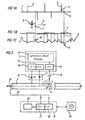
- the device used here consists of a receiver and a combined receiving and transmitting coil with a built-in geophone. This device is provided with electronics (transmitter 2 / receiver 1) which inductively transmits the cable via the transmitter coil at a specific frequency and is received by a receiver E2 in the pulse-echo device, which in turn activates the first transmitter S1. The latter applies a signal to the cable, which is picked up again by the receiver E1 via the receiving coil.
- the time difference between the pulsed signals S1 and E2 is multiplied by half the cable-typical propagation speed.
- the result is fed to a module which has the task of indicating to the operator of the pulse-echo device the position of the line seeker above the route in the form of a luminous point on the flexion image.
- the line seeker can now be directed to the cable fault via radio or the like, the illuminated dot moving in the same direction and speed on the reflection image as the line seeker above the route. Since the actual cable fault and the assumed fault cannot be identified separately on the reflection image, especially in branched low-voltage networks, safety becomes a problem the pulse-echo measuring device is replaced by a shock wave generator, in which case the person searching for the fault has already placed his above-ground fault marks at the location of the suspected fault and is located directly above one of these points.
- shock wave generator With the shock wave generator, a rollover is generated at the fault location, as already described, and the intensity is directed to the receiver via the geophone. If no rollover signal is received, the person searching for the fault is in the wrong place, but can successfully use the geophone at the point of the fault that has already been marked.
- this method saves you from pinpointing using the shock wave method for low-resistance faults.
- This red dot method can also be used successfully to read a cable from a cable bundle.
- a cable 1 is shown, on which several cables 2, 3 attach.
- cable 3 at point 4 is the cable error, whereby due to the pulse-echo diagram according to FIG. 1 c, the cable error could also be at point 5.
- the screen image 9 shown in FIG. 1 c contains various maxima and minima, with an error at the location of curves minima 11. Based on the evaluation of the screen image 9 and the knowledge of measuring in a branched network, the cable errors would be assumed at point 4 or 5 according to FIG. 1b.
- a line seeker 6 with a portable transmitting and receiving device 7 simultaneously moves along the cable 1 in the direction of the arrow 8.
- a luminous dot 10 is generated on the screen image 9 of the reflection diagram, this luminous dot 10 according to the vertical, dashed line exactly with the current position of the transmitting and receiving device 7 along the one to be examined Cable 1 matches.
- the measurement technician in the stationary measuring vehicle now switches on a shock wave generator so that high-energy arcing is generated at the location of the cable fault 4 and the line seeker 6 can immediately determine these high-energy arcing above ground with a microphone 18 (FIG. 2) and an assigned receiver 15. Either it is already above the cable fault at point 4, or it is still at point 5 and knows, after it cannot determine with its transmitter and receiver device 7, that it is at the wrong point, so that it immediately leads to Point 4 of the real cable fault can pass over.
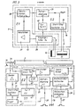
- a pulse-echo device 25 with an associated screen image, on which a diagram according to FIG. 1 c is generated, is coupled to a novel transmission and reception device 19.
- This transmitting and receiving device consists of a first transmitter 22 which galvanically connects the cable over the cable start 39 at a frequency f . is emitted, a receiver 21 being arranged in the transmitting and receiving device, which only selectively receives a pulsed signal of frequency f b .
- the transmission signal of the frequency f galvanically coupled onto the cable 3. is assigned in the portable transmitting and receiving device 7, which the line seeker 6 carries with him, a second receiver 13, which inductively receives the transmitted signal via the cable 3 via a cable 3 transmitting signal f a , which in turn receives one activates (controls) the second transmitter 14, which couples a pulsed transmission signal of a different frequency f b onto the cable 3 via a transmission coil 17.
- This transmission signal f b is received via the first receiver 21 connected to the cable 3.
- the transit time difference between the emitted signal fa and the received signal fb is then measured and entered into a computing module 20, which calculates the distance of the portable transmitting and receiving device 7 from the start of the cable 39 and as a luminous dot on the screen image of the pulse-echo device 25 displays.
- the required signals are fed back to cable 3 via line 23. If, in accordance with the above description, the line seeker 6 has been directed to the suspected location of the cable fault (point 4) with his transmitting and receiving device, then the stationary transmitting and receiving device 19 is decoupled from the cable and instead a shock world generator is coupled. There are now high-energy flashovers at point 4 of the cable 3, which due to their loud crackling on the earth's surface are heard and recorded with a microphone 18 of the portable transmitting and receiving device 7. The microphone 18 is assigned a third receiver 15, which emits its signal to a visual and acoustic display 12, so that the line seeker 6 has now found the fault in the cable 3 at point 4 by observing the display 12.
- An external trigger signal on line 38 triggers trigger 32, which in turn triggers start / stop oscillator 35, which oscillates at frequency f a .
- the input circuit 3'4 of the receiver 21 is blocked via the gate circuit 47.
- the signal with the frequency f a which the oscillator 35 generates, is amplified by the transmitter 31 and supplied to the cable start 39.
- the thus fed to the cable 3 signal is detected by the receiver coil 16 of the portable transmitting and receiving device 7 and an input filter 26 supplied to the quenzf only for the frequency a, is permeable.
- the output signal is fed to an amplifier 27 which acts on a pulse shaper where the sine signal is converted into a square wave signal.
- This signal is then delayed by time X1 (time delay module 29), this time-delayed signal being fed to a gate circuit 40, which in turn blocks the input filter 26 for the second receiver 13.
- the time-delayed signal at the output of the time delay module 29 is simultaneously fed to a start / stop oscillator 30, which acts on the transmission coil 17 with the frequency f b .
- the transmission coil 17 inductively transmits this signal to the cable 3.
- This signal is in turn fed to the input circuit 34 of the receiver 21 at the beginning of the cable 39 via the line 23, where it then passes through an amplifier 41 and is fed to a pulse shaper 43.
- the amplifier outputs its signal to an AVR module 42 (automatic gain control) and to the pulse shaper 43. This converts the sinusoidal signal supplied to it into a square-wave signal and passes it on to the control 44 for the light mark.
- the control 44 generates a control signal for generating a red dot from the two output signals of the pulse shaper 43 and the time delay 45 and an external sawtooth signal via the line 36 (bright mark display 33).
- This signal can be fed via line 37 to the screen image of the pulse-echo device 25, where it then appears as a red dot 10 in the pulse-echo diagram of the illustration in FIG. 1c.
- the current location of the line seeker 6 with his transmitting and receiving device 7 along the cable 1, 3 can be determined at any time.
- the measurement method now described can also be used without a shock wave generator for low-resistance faults, e.g. in low voltage and telecommunication cables.
Landscapes
- Physics & Mathematics (AREA)
- General Physics & Mathematics (AREA)
- Locating Faults (AREA)
- Investigating Materials By The Use Of Optical Means Adapted For Particular Applications (AREA)
- Monitoring And Testing Of Transmission In General (AREA)
Claims (6)
Priority Applications (1)
| Application Number | Priority Date | Filing Date | Title |
|---|---|---|---|
| AT83111338T ATE19439T1 (de) | 1982-11-16 | 1983-11-12 | Verfahren zur kabelfehler-ortung und vorrichtung zur ausfuehrung des verfahrens. |
Applications Claiming Priority (2)
| Application Number | Priority Date | Filing Date | Title |
|---|---|---|---|
| DE19823242412 DE3242412A1 (de) | 1982-11-16 | 1982-11-16 | Verfahren zur kabelfehler-ortung und vorrichtung zur ausfuehrung des verfahrens |
| DE3242412 | 1982-11-16 |
Publications (3)
| Publication Number | Publication Date |
|---|---|
| EP0109079A2 EP0109079A2 (fr) | 1984-05-23 |
| EP0109079A3 EP0109079A3 (en) | 1984-07-04 |
| EP0109079B1 true EP0109079B1 (fr) | 1986-04-23 |
Family
ID=6178292
Family Applications (1)
| Application Number | Title | Priority Date | Filing Date |
|---|---|---|---|
| EP83111338A Expired EP0109079B1 (fr) | 1982-11-16 | 1983-11-12 | Méthode pour localiser des défauts de câble et dispositif pour sa mise en oeuvre |
Country Status (3)
| Country | Link |
|---|---|
| EP (1) | EP0109079B1 (fr) |
| AT (1) | ATE19439T1 (fr) |
| DE (2) | DE3242412A1 (fr) |
Families Citing this family (3)
| Publication number | Priority date | Publication date | Assignee | Title |
|---|---|---|---|---|
| DE3737373C2 (de) * | 1987-03-28 | 1996-02-22 | Baur Pruef Und Mestechnik Kg | Verfahren zur Isolationsprüfung von verlegten Kabeln und zur Ortung von Kabelfehlern sowie Vorrichtung zur Durchführung des Verfahrens |
| US5352984A (en) * | 1992-11-04 | 1994-10-04 | Cable Repair Systems Corporation | Fault and splice finding system and method |
| CN106405321B (zh) * | 2016-06-28 | 2023-08-11 | 国网山东省电力公司龙口市供电公司 | 一种电力线缆故障检测设备 |
Family Cites Families (5)
| Publication number | Priority date | Publication date | Assignee | Title |
|---|---|---|---|---|
| DE2138108A1 (de) * | 1970-10-02 | 1972-04-06 | Rft Messelektronik Dresden Veb | Verfahren zur punktgenauen Lokah sierung von Fehlerstellen in Kabeln |
| DE2351318A1 (de) * | 1972-10-16 | 1974-04-25 | Balteau Sa | Geraet zur fehlerortung an elektrischen kabeln |
| US4370610A (en) * | 1978-08-30 | 1983-01-25 | Bicc Public Limited Company | Locating sheath faults in underground power supply cables |
| US4322677A (en) * | 1979-03-16 | 1982-03-30 | Minnesota Mining And Manufacturing Company | System and method for locating resistive faults and interconnect errors in multi-conductor cables |
| DE3128061A1 (de) * | 1981-07-16 | 1983-02-03 | Howaldtswerke-Deutsche Werft Ag Hamburg Und Kiel, 2300 Kiel | Verfahren zur fehlerortung an elektrischen leitern |
-
1982
- 1982-11-16 DE DE19823242412 patent/DE3242412A1/de active Granted
-
1983
- 1983-11-12 AT AT83111338T patent/ATE19439T1/de not_active IP Right Cessation
- 1983-11-12 EP EP83111338A patent/EP0109079B1/fr not_active Expired
- 1983-11-12 DE DE8383111338T patent/DE3363195D1/de not_active Expired
Also Published As
| Publication number | Publication date |
|---|---|
| DE3242412C2 (fr) | 1989-01-05 |
| DE3242412A1 (de) | 1984-05-24 |
| EP0109079A3 (en) | 1984-07-04 |
| EP0109079A2 (fr) | 1984-05-23 |
| DE3363195D1 (en) | 1986-05-28 |
| ATE19439T1 (de) | 1986-05-15 |
Similar Documents
| Publication | Publication Date | Title |
|---|---|---|
| DE3228208C2 (fr) | ||
| EP0225337B1 (fr) | Dispositif pour la detection de decharges en couronne des lignes aeriennes a courant alternatif | |
| EP0063695B1 (fr) | Procédé pour mésurer des temps de transit d'impulsions, des localisations de défauts et des atténuations dans des câbles et des guides d'ondes optiques | |
| EP2405279A2 (fr) | Procédé et dispositif destinés à la localisation d'erreurs de câblage | |
| CH662022A5 (de) | Verfahren und einrichtung zur ueberwachung einer digitalen uebertragungsanlage. | |
| WO2018176071A1 (fr) | Procédé servant à localiser avec précision un défaut de câble d'un câble enterré | |
| EP0109079B1 (fr) | Méthode pour localiser des défauts de câble et dispositif pour sa mise en oeuvre | |
| AT521058B1 (de) | Verfahren zur Feinortung eines Kabelfehlers eines erdverlegten Kabels | |
| EP3643579A1 (fr) | Dispositif et procédé de surveillance d'un aiguillage | |
| DE3008187A1 (de) | System zum ermitteln von fehlerstellen in einem optischen faseruebermittlungssystem | |
| DE1806875B2 (de) | Rohrmolch zur Erkennung und Ortung von Lecks in Rohrleitungen | |
| DE2717412C3 (de) | Durchgangsprüfgerät für Lichtleitfasern | |
| DE2160766A1 (de) | Verfahren und Durchfuhrungsanordnung zur Messung der Entfernung eines bestimm ten Objektes | |
| DE2639831A1 (de) | Pruefverfahren und -geraet | |
| DE1948540A1 (de) | Vorrichtung zur Fernmessung der Nichtlinearitaet von Leitungsverstaerkern | |
| DE3019264C2 (de) | Verfahren zum Spleißen mehradriger optischer Kabel | |
| DE2640012A1 (de) | Verfahren und geraet zur ortung von kurzschluessen in mit mehreren adern und einer oder mehreren abschirmungen versehenen leitungen, insbesondere des berg- und tunnelbaus | |
| DE1762531C3 (de) | Verfahren zum Messen der frequenzabhängigen Dämpfung von Fernsprechleitungen | |
| DE1809536A1 (de) | Schaltungsanordnung zur Abbildung eines Toleranzbereiches auf einem Kathodenstrahlanzeiger | |
| DE2644157A1 (de) | Geraet zur lokalisierung von fehlerstellen in elektrischen kabeln | |
| DE10146859A1 (de) | Verfahren und Vorrichtung zur Lokalisierung eines Leitungsfehlers | |
| DE2806945A1 (de) | Vorrichtung zur abtrennung von abschnitten eines langgestreckten gutes | |
| DE3517023A1 (de) | Phasenvergleichs- und spannungspruefer, insbesondere fuer den mittelspannungsbereich | |
| DE3901277C2 (fr) | ||
| DE2140257A1 (de) | Verfahren zur Messung des Dopplereffektes zur Bestimmung der von einem Fahrzeug bezüglich einer Bezugsfläche durchfahrenden Bahn und Vorrichtung zu seiner Durchführung |
Legal Events
| Date | Code | Title | Description |
|---|---|---|---|
| PUAI | Public reference made under article 153(3) epc to a published international application that has entered the european phase |
Free format text: ORIGINAL CODE: 0009012 |
|
| PUAL | Search report despatched |
Free format text: ORIGINAL CODE: 0009013 |
|
| AK | Designated contracting states |
Designated state(s): AT BE CH DE FR GB IT LI LU NL SE |
|
| RHK1 | Main classification (correction) |
Ipc: G01R 31/08 |
|
| AK | Designated contracting states |
Designated state(s): AT BE CH DE FR GB IT LI LU NL SE |
|
| 17P | Request for examination filed |
Effective date: 19840705 |
|
| GRAA | (expected) grant |
Free format text: ORIGINAL CODE: 0009210 |
|
| AK | Designated contracting states |
Kind code of ref document: B1 Designated state(s): AT BE CH DE FR GB IT LI LU NL SE |
|
| PG25 | Lapsed in a contracting state [announced via postgrant information from national office to epo] |
Ref country code: IT Free format text: LAPSE BECAUSE OF FAILURE TO SUBMIT A TRANSLATION OF THE DESCRIPTION OR TO PAY THE FEE WITHIN THE PRESCRIBED TIME-LIMIT;WARNING: LAPSES OF ITALIAN PATENTS WITH EFFECTIVE DATE BEFORE 2007 MAY HAVE OCCURRED AT ANY TIME BEFORE 2007. THE CORRECT EFFECTIVE DATE MAY BE DIFFERENT FROM THE ONE RECORDED. Effective date: 19860423 Ref country code: FR Free format text: THE PATENT HAS BEEN ANNULLED BY A DECISION OF A NATIONAL AUTHORITY Effective date: 19860423 |
|
| REF | Corresponds to: |
Ref document number: 19439 Country of ref document: AT Date of ref document: 19860515 Kind code of ref document: T |
|
| PG25 | Lapsed in a contracting state [announced via postgrant information from national office to epo] |
Ref country code: SE Effective date: 19860430 |
|
| REF | Corresponds to: |
Ref document number: 3363195 Country of ref document: DE Date of ref document: 19860528 |
|
| EN | Fr: translation not filed | ||
| PGFP | Annual fee paid to national office [announced via postgrant information from national office to epo] |
Ref country code: AT Payment date: 19861117 Year of fee payment: 4 |
|
| PG25 | Lapsed in a contracting state [announced via postgrant information from national office to epo] |
Ref country code: LU Free format text: LAPSE BECAUSE OF NON-PAYMENT OF DUE FEES Effective date: 19861130 |
|
| PGFP | Annual fee paid to national office [announced via postgrant information from national office to epo] |
Ref country code: NL Payment date: 19861130 Year of fee payment: 4 |
|
| PLBE | No opposition filed within time limit |
Free format text: ORIGINAL CODE: 0009261 |
|
| STAA | Information on the status of an ep patent application or granted ep patent |
Free format text: STATUS: NO OPPOSITION FILED WITHIN TIME LIMIT |
|
| 26N | No opposition filed | ||
| PG25 | Lapsed in a contracting state [announced via postgrant information from national office to epo] |
Ref country code: AT Effective date: 19871112 |
|
| PG25 | Lapsed in a contracting state [announced via postgrant information from national office to epo] |
Ref country code: LI Effective date: 19871130 Ref country code: CH Effective date: 19871130 Ref country code: BE Effective date: 19871130 |
|
| BERE | Be: lapsed |
Owner name: SEBA-DYNATRONIC MESS- UND ORTUNGSTECHNIK G.M.B.H. Effective date: 19871130 |
|
| PG25 | Lapsed in a contracting state [announced via postgrant information from national office to epo] |
Ref country code: NL Effective date: 19880601 |
|
| NLV4 | Nl: lapsed or anulled due to non-payment of the annual fee | ||
| GBPC | Gb: european patent ceased through non-payment of renewal fee | ||
| REG | Reference to a national code |
Ref country code: CH Ref legal event code: PL |
|
| PG25 | Lapsed in a contracting state [announced via postgrant information from national office to epo] |
Ref country code: GB Effective date: 19881122 |
|
| PGFP | Annual fee paid to national office [announced via postgrant information from national office to epo] |
Ref country code: DE Payment date: 19890131 Year of fee payment: 6 |
|
| PG25 | Lapsed in a contracting state [announced via postgrant information from national office to epo] |
Ref country code: DE Effective date: 19900801 |