EP0109079B1 - Method of locating cable faults, and device for performing this method - Google Patents
Method of locating cable faults, and device for performing this method Download PDFInfo
- Publication number
- EP0109079B1 EP0109079B1 EP83111338A EP83111338A EP0109079B1 EP 0109079 B1 EP0109079 B1 EP 0109079B1 EP 83111338 A EP83111338 A EP 83111338A EP 83111338 A EP83111338 A EP 83111338A EP 0109079 B1 EP0109079 B1 EP 0109079B1
- Authority
- EP
- European Patent Office
- Prior art keywords
- cable
- receiver
- transmitter
- transmission
- pulse
- Prior art date
- Legal status (The legal status is an assumption and is not a legal conclusion. Google has not performed a legal analysis and makes no representation as to the accuracy of the status listed.)
- Expired
Links
Images
Classifications
-
- G—PHYSICS
- G01—MEASURING; TESTING
- G01R—MEASURING ELECTRIC VARIABLES; MEASURING MAGNETIC VARIABLES
- G01R31/00—Arrangements for testing electric properties; Arrangements for locating electric faults; Arrangements for electrical testing characterised by what is being tested not provided for elsewhere
- G01R31/08—Locating faults in cables, transmission lines, or networks
- G01R31/11—Locating faults in cables, transmission lines, or networks using pulse reflection methods
Definitions
- the invention relates to a method for cable fault location according to the preamble of claim 1 and an apparatus for performing this method.
- Locating a cable fault using the pulse-echo method is particularly difficult in branched low-voltage networks, since the reflection images look very confusing due to the many sleeves, branches and end reflections. In addition, it is very difficult and time-consuming to locate the error in the branched line section after evaluating the reflection image.
- the cause is i.a. to search in that the cable route is not always exactly known and therefore a cable search with an audio frequency system must be carried out.
- the line to be searched for is subjected to an audio frequency current, a magnetic field being created around the current-carrying conductor, which position can be located with the aid of suitable measuring devices (receiver and receiver coil) and thus leads to the determination of the line course.
- shock wave method is now used as the third measurement method for pinpoint location.
- a shock wave generator generates high-energy flashovers at the fault, the sound field on the surface of the earth being indicated optically and acoustically by the receiving device (receiver and geophone) and thus leading to pinpoint location, with this receiving device again running the previously marked route must be determined in order to determine the intensity of the sound maximum.
- the object of the present invention is to make a measurement method mentioned at the outset substantially less labor-intensive.
- An essential feature of the present invention is that, in the course of the pulse-echo measurement, a luminous point is simultaneously generated on the screen image of the pulse-echo measuring device, this luminous point representing the current position of the portable transmitter. and reproduces the receiving device along the measured cable.
- the person who carries the portable transmitting and receiving device with him can now be directed to the location of the suspected error by means of radiotelephony, the luminous point on the reflection diagram generated by the system proposed according to the invention moving along on the reflection diagram.
- This results in a significant simplification of work because as soon as the transmitting and receiving device has arrived at the suspected fault location, the pulse-echo measuring device is removed from the cable to be examined and a shock wave generator is connected instead. Now high-energy flashovers are generated, and the person standing at the location of the suspected error now receives the flashes of the underground cable, which can be heard above ground, with a microphone coupled to the transmitting and receiving device and a third receiver arranged therein. The error is then found immediately.
- the stationary pulse-echo measuring device is connected to a special stationary transmitting and receiving device, which is associated with a portable transmitting and receiving device that the line seeker carries with him.
- the pulse-echo measuring device stationed in a cable test vehicle or in the system to be measured, is connected to the faulty cable and a normal runtime measurement is then carried out. During this measurement, a second measurement technician starts searching for the line.
- the device used here consists of a receiver and a combined receiving and transmitting coil with a built-in geophone. This device is provided with electronics (transmitter 2 / receiver 1) which inductively transmits the cable via the transmitter coil at a specific frequency and is received by a receiver E2 in the pulse-echo device, which in turn activates the first transmitter S1. The latter applies a signal to the cable, which is picked up again by the receiver E1 via the receiving coil.
- the time difference between the pulsed signals S1 and E2 is multiplied by half the cable-typical propagation speed.
- the result is fed to a module which has the task of indicating to the operator of the pulse-echo device the position of the line seeker above the route in the form of a luminous point on the flexion image.
- the line seeker can now be directed to the cable fault via radio or the like, the illuminated dot moving in the same direction and speed on the reflection image as the line seeker above the route. Since the actual cable fault and the assumed fault cannot be identified separately on the reflection image, especially in branched low-voltage networks, safety becomes a problem the pulse-echo measuring device is replaced by a shock wave generator, in which case the person searching for the fault has already placed his above-ground fault marks at the location of the suspected fault and is located directly above one of these points.
- shock wave generator With the shock wave generator, a rollover is generated at the fault location, as already described, and the intensity is directed to the receiver via the geophone. If no rollover signal is received, the person searching for the fault is in the wrong place, but can successfully use the geophone at the point of the fault that has already been marked.
- this method saves you from pinpointing using the shock wave method for low-resistance faults.
- This red dot method can also be used successfully to read a cable from a cable bundle.
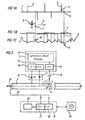
- a cable 1 is shown, on which several cables 2, 3 attach.
- cable 3 at point 4 is the cable error, whereby due to the pulse-echo diagram according to FIG. 1 c, the cable error could also be at point 5.
- the screen image 9 shown in FIG. 1 c contains various maxima and minima, with an error at the location of curves minima 11. Based on the evaluation of the screen image 9 and the knowledge of measuring in a branched network, the cable errors would be assumed at point 4 or 5 according to FIG. 1b.
- a line seeker 6 with a portable transmitting and receiving device 7 simultaneously moves along the cable 1 in the direction of the arrow 8.
- a luminous dot 10 is generated on the screen image 9 of the reflection diagram, this luminous dot 10 according to the vertical, dashed line exactly with the current position of the transmitting and receiving device 7 along the one to be examined Cable 1 matches.
- the measurement technician in the stationary measuring vehicle now switches on a shock wave generator so that high-energy arcing is generated at the location of the cable fault 4 and the line seeker 6 can immediately determine these high-energy arcing above ground with a microphone 18 (FIG. 2) and an assigned receiver 15. Either it is already above the cable fault at point 4, or it is still at point 5 and knows, after it cannot determine with its transmitter and receiver device 7, that it is at the wrong point, so that it immediately leads to Point 4 of the real cable fault can pass over.
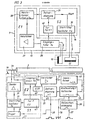
- a pulse-echo device 25 with an associated screen image, on which a diagram according to FIG. 1 c is generated, is coupled to a novel transmission and reception device 19.
- This transmitting and receiving device consists of a first transmitter 22 which galvanically connects the cable over the cable start 39 at a frequency f . is emitted, a receiver 21 being arranged in the transmitting and receiving device, which only selectively receives a pulsed signal of frequency f b .
- the transmission signal of the frequency f galvanically coupled onto the cable 3. is assigned in the portable transmitting and receiving device 7, which the line seeker 6 carries with him, a second receiver 13, which inductively receives the transmitted signal via the cable 3 via a cable 3 transmitting signal f a , which in turn receives one activates (controls) the second transmitter 14, which couples a pulsed transmission signal of a different frequency f b onto the cable 3 via a transmission coil 17.
- This transmission signal f b is received via the first receiver 21 connected to the cable 3.
- the transit time difference between the emitted signal fa and the received signal fb is then measured and entered into a computing module 20, which calculates the distance of the portable transmitting and receiving device 7 from the start of the cable 39 and as a luminous dot on the screen image of the pulse-echo device 25 displays.
- the required signals are fed back to cable 3 via line 23. If, in accordance with the above description, the line seeker 6 has been directed to the suspected location of the cable fault (point 4) with his transmitting and receiving device, then the stationary transmitting and receiving device 19 is decoupled from the cable and instead a shock world generator is coupled. There are now high-energy flashovers at point 4 of the cable 3, which due to their loud crackling on the earth's surface are heard and recorded with a microphone 18 of the portable transmitting and receiving device 7. The microphone 18 is assigned a third receiver 15, which emits its signal to a visual and acoustic display 12, so that the line seeker 6 has now found the fault in the cable 3 at point 4 by observing the display 12.
- An external trigger signal on line 38 triggers trigger 32, which in turn triggers start / stop oscillator 35, which oscillates at frequency f a .
- the input circuit 3'4 of the receiver 21 is blocked via the gate circuit 47.
- the signal with the frequency f a which the oscillator 35 generates, is amplified by the transmitter 31 and supplied to the cable start 39.
- the thus fed to the cable 3 signal is detected by the receiver coil 16 of the portable transmitting and receiving device 7 and an input filter 26 supplied to the quenzf only for the frequency a, is permeable.
- the output signal is fed to an amplifier 27 which acts on a pulse shaper where the sine signal is converted into a square wave signal.
- This signal is then delayed by time X1 (time delay module 29), this time-delayed signal being fed to a gate circuit 40, which in turn blocks the input filter 26 for the second receiver 13.
- the time-delayed signal at the output of the time delay module 29 is simultaneously fed to a start / stop oscillator 30, which acts on the transmission coil 17 with the frequency f b .
- the transmission coil 17 inductively transmits this signal to the cable 3.
- This signal is in turn fed to the input circuit 34 of the receiver 21 at the beginning of the cable 39 via the line 23, where it then passes through an amplifier 41 and is fed to a pulse shaper 43.
- the amplifier outputs its signal to an AVR module 42 (automatic gain control) and to the pulse shaper 43. This converts the sinusoidal signal supplied to it into a square-wave signal and passes it on to the control 44 for the light mark.
- the control 44 generates a control signal for generating a red dot from the two output signals of the pulse shaper 43 and the time delay 45 and an external sawtooth signal via the line 36 (bright mark display 33).
- This signal can be fed via line 37 to the screen image of the pulse-echo device 25, where it then appears as a red dot 10 in the pulse-echo diagram of the illustration in FIG. 1c.
- the current location of the line seeker 6 with his transmitting and receiving device 7 along the cable 1, 3 can be determined at any time.
- the measurement method now described can also be used without a shock wave generator for low-resistance faults, e.g. in low voltage and telecommunication cables.
Abstract
Description
Gegenstand der Erfindung ist ein Verfahren zur Kabelfehlerortung nach dem Oberbegriff des Patentanspruchs 1 und eine Vorrichtung zur Ausführung dieses Verfahrens.The invention relates to a method for cable fault location according to the preamble of
Die Ortung eines Kabelfehlers nach dem Impuls-Echo-Verfahren bereitet vor allem in verzweigten Niederspannungs-Netzen Schwierigkeiten, da die Reflexionsbilder infolge der vielen Muffen, Verzweigungen und Endreflexionen sehr verwirrend aussehen. Ausserdem lässt sich nur sehr schwer und mit grossem Zeitaufwand der Fehler nach Auswertung des Reflexionsbildes in dem verzweigten Leitungsabschnitt lokalisieren. Die Ursache ist u.a. darin zu suchen, dass der Kabelverlauf nicht immer genau bekannt ist und somit eine Kabelsuche mit einer Tonfrequenzanlage durchgeführt werden muss. Hierbei wird die zu suchende Leitung mit einem Tonfrequenzstrom beaufschlagt, wobei um den stromdurchflossenen Leiter ein Magnetfeld entsteht, dasmit Hilfegeeigneter Messgeräte (Empfänger und Empfangsspule) in seiner Lage geortet werden kann und somit zur Bestimmung des Leitungsverlaufes führt.Locating a cable fault using the pulse-echo method is particularly difficult in branched low-voltage networks, since the reflection images look very confusing due to the many sleeves, branches and end reflections. In addition, it is very difficult and time-consuming to locate the error in the branched line section after evaluating the reflection image. The cause is i.a. to search in that the cable route is not always exactly known and therefore a cable search with an audio frequency system must be carried out. In this case, the line to be searched for is subjected to an audio frequency current, a magnetic field being created around the current-carrying conductor, which position can be located with the aid of suitable measuring devices (receiver and receiver coil) and thus leads to the determination of the line course.
Nach oberirdischer Markierung der unterirdischen Kabeltrasse ist bei verzweigten Kabeln immer noch nicht eindeutig bekannt, in welchem Leitungsabschnitt sich der Fehler befindet.After marking the underground cable route above ground, it is still not clearly known in the case of branched cables in which line section the fault is located.
Während die Messverfahren, Imputs-Echo-Messungen und Tonfrequenz, zur Fehlereingrenzung führten, kommt jetzt zur punktgenauen Ortung als drittes Messverfahren die Stosswellen-Methode zum Einsatz.While the measurement methods, imput-echo measurements and audio frequency, led to error isolation, the shock wave method is now used as the third measurement method for pinpoint location.
Bei diesem bekannten Verfahren erzeugt ein Stosswellen-Generator an der Fehlerstetlle energiereiche Überschläge, deren Schallfeld an der Erdoberfläche von der Empfangseinrichtung (Empfänger und Geophon) optisch und akustisch angezeigt wird und somit zur punktgenauen Ortung führt, wobei mit dieser Empfangseinrichtung nochmals die vorher markierte Trasse abgelaufen werden muss, um die Intensität des Schallmaximums feststellen zu können.In this known method, a shock wave generator generates high-energy flashovers at the fault, the sound field on the surface of the earth being indicated optically and acoustically by the receiving device (receiver and geophone) and thus leading to pinpoint location, with this receiving device again running the previously marked route must be determined in order to determine the intensity of the sound maximum.
Da zu dieser Messmethode der Kabelfehlerortung alle drei Verfahren (Impuls-Echo-Messung, Tonfrequenz und Stosswellen-Methode) nur separat zur Anwendung kommen, ist die Ortung des Kabelfehlers nach dem Stand der Technik eine sehr aufwendige Angelegenheit.Since all three methods (pulse-echo measurement, audio frequency and shock wave method) are only used separately for this measurement method of cable fault location, the location of the cable fault according to the prior art is a very complex matter.
Die vorliegende Erfindung hat sich die Aufgabe gestellt, ein eingangs genanntes Messverfahren wesentlich weniger arbeitsaufwendig zu gestalten.The object of the present invention is to make a measurement method mentioned at the outset substantially less labor-intensive.
Zur Lösung der gestellten Aufgabe dienen die im kennzeichnenden Teil des Anspruchs 1 angegebenen technischen Verfahrensschritte.The technical process steps specified in the characterizing part of
Wesentliches Merkmal der vorliegenden Erfindung ist nach dem Gegenstand des Anspruchs 1, dass im Verlaufe der Impuls-Echo-Messung gleichzeitig ein Leuchtpunkt auf dem Schirmbild des Impuls-Echo-Messgerätes erzeugt wird, wobei dieser Leuchtpunkt die momentane Lage (Stellung) der tragbaren Sende- und Empfangseinrichtung längs des gemessenen Kabels wiedergibt.An essential feature of the present invention is that, in the course of the pulse-echo measurement, a luminous point is simultaneously generated on the screen image of the pulse-echo measuring device, this luminous point representing the current position of the portable transmitter. and reproduces the receiving device along the measured cable.
Die Person, welche die tragbare Sende- und Empfangseinrichtung mit sich führt, kann nun mittels Sprechfunk zu dem Ort des vermuteten Fehlers hindirigiert werden, wobei auf dem Schirmbild der durch die erfindungsgemäss vorgeschlagene Anlage erzeugte Leuchtpunkt auf dem Reflexionsdiagramm mitwandert. Es ergibt sich damit eine wesentliche Arbeitsvereinfachung, denn sobald die Sende- und Empfangseinrichtung an dervermuteten Fehlerstelle angekommen ist, wird das Impuls-Echo- Messgerät von dem zu untersuchenden Kabel entfernt und statt dessen ein Stosswellen-Generator angeschlossen. Es werden nun energiereiche Überschläge erzeugt, und die am Ort des vermuteten Fehlers stehende Person empfängt nun mit einem an der Sende- und Empfangseinrichtung angekoppelten Mikrophon und einem darin angeordneten dritten Empfänger die akustisch, oberirdisch zu hörenden Überschläge des unterirdisch verlegten Kabels. Der Fehler ist dann somit sofort gefunden.The person who carries the portable transmitting and receiving device with him can now be directed to the location of the suspected error by means of radiotelephony, the luminous point on the reflection diagram generated by the system proposed according to the invention moving along on the reflection diagram. This results in a significant simplification of work, because as soon as the transmitting and receiving device has arrived at the suspected fault location, the pulse-echo measuring device is removed from the cable to be examined and a shock wave generator is connected instead. Now high-energy flashovers are generated, and the person standing at the location of the suspected error now receives the flashes of the underground cable, which can be heard above ground, with a microphone coupled to the transmitting and receiving device and a third receiver arranged therein. The error is then found immediately.
Diese schnelle Fehlersuche ist nur deshalb möglich, weil das stationäre Impuls-Echo-Messgerät mit einer besonderen stationären Sende- und Empfangseinrichtung verbunden ist, der eine tragbare Sende- und Empfangseinrichtung zugeordnet ist, die der Leitungssuchende mit sich führt.This quick troubleshooting is only possible because the stationary pulse-echo measuring device is connected to a special stationary transmitting and receiving device, which is associated with a portable transmitting and receiving device that the line seeker carries with him.
Das Impuls-Echo-Messgerät, in einem Kabelmesswagen oder in der einzumessenden Anlage stationiert, wird mit dem fehlerbehafteten Kabel verbunden und eine normale Laufzeitmessung wird dann vorgenommen. Während dieser Messung beginnt ein zweiter Messtechniker mit der Leitungssuche. Die hierbei zur Anwendung kommende Einrichtung besteht aus einem Empfänger und einer kombinierten Empfangs- und Sendespule mit eingebautem Geophon. Diese Einrichtung ist mit einer Elektronik (Sender 2/Empfänger 1 ) versehen, diedas Kabel über die Sendespule mit einer bestimmten Frequenz induktiv besendet und von einem Empfänger E2 im Impuls-Echo-Gerät empfangen wird, der wiederum den ersten Sender S1 aktiviert. Dieser beaufschlagt das Kabel mit einem Signal, welches erneut über die Empfangsspule von dem Empfänger E1 aufgenommen wird.The pulse-echo measuring device, stationed in a cable test vehicle or in the system to be measured, is connected to the faulty cable and a normal runtime measurement is then carried out. During this measurement, a second measurement technician starts searching for the line. The device used here consists of a receiver and a combined receiving and transmitting coil with a built-in geophone. This device is provided with electronics (
Die Zeitdifferenz zwischen den gepulsten Signalen S1 und E2 wird mit der halben kabeltypischen Fortpflanzungsgeschwindigkeit multipliziert. Das Ergebnis wird einem Modul zugeführt, das die Aufgabe hat, dem Bediener des Impuls-Echo-Gerätes den Standpunkt des Leitungssuchenden über der Trasse in Form eines Leuchtpunktes auf dem Flexionsbild anzugeben.The time difference between the pulsed signals S1 and E2 is multiplied by half the cable-typical propagation speed. The result is fed to a module which has the task of indicating to the operator of the pulse-echo device the position of the line seeker above the route in the form of a luminous point on the flexion image.
Der Leitungssuchende kann jetzt über Sprechfunk oder ähnlichem zum Kabelfehlerdirigiertwerden, wobei der Leuchtpunkt sich in gleicher Richtung und Geschwindigkeit auf dem Reflexionsbild bewegt wie der Leitungssuchende über der Trasse. Da gerade in verzweigten Niederspannungsnetzen der tatsächliche Kabelfehler und der angenommene Fehler nicht getrennt auf dem Reflexionsbild auszumachen sind, wird zur Sicherheit das Impuls-Echo-Messgerät gegen einen Stosswellen-Generator ausgetauscht, wobei in diesem Fall der Fehlersuchende bereits seine oberirdische Fehlermarkierungen am Ort des vermuteten Fehlers gesetzt hat und sich direkt über einem dieser Punkte befindet.The line seeker can now be directed to the cable fault via radio or the like, the illuminated dot moving in the same direction and speed on the reflection image as the line seeker above the route. Since the actual cable fault and the assumed fault cannot be identified separately on the reflection image, especially in branched low-voltage networks, safety becomes a problem the pulse-echo measuring device is replaced by a shock wave generator, in which case the person searching for the fault has already placed his above-ground fault marks at the location of the suspected fault and is located directly above one of these points.
Mit dem Stosswellen-Generator wird an der Fehlerstelle, wie bereits beschrieben, ein Überschlag erzeugt und die Intensität über das Geophon an den Empfänger geleitet. Wird kein Überschlagssignal empfangen, befindet sich der Fehlersuchende an der falschen Stelle, kann aber gezielt an der schon vorher markierten Fehlerstelle das Geophon mit Erfolg einsetzen.With the shock wave generator, a rollover is generated at the fault location, as already described, and the intensity is directed to the receiver via the geophone. If no rollover signal is received, the person searching for the fault is in the wrong place, but can successfully use the geophone at the point of the fault that has already been marked.
Dieses Verfahren bringt weitere erhebliche Erleichterungen und Zeitersparnis bei der Fehlerortung auf dem Fernmeldesektor mit sich, da auf diesem Gebiet wegen der strengen Bestimmungen zur punktgenauen Fehlerortung der Einsatz von Hochspannungsgeräten nicht erlaubt ist. Eine Fehlersuche ist bei niederohmigen Fehlern daher auch ohne das Stosswellen-Ortungsverfahren nach der Erfindung möglich.This procedure brings further considerable simplifications and time savings in the fault location in the telecommunications sector, since the use of high-voltage devices is not permitted in this area because of the strict provisions for pinpointing faults. In the case of low-resistance faults, troubleshooting is therefore also possible without the shock wave location method according to the invention.
Weiterhin erspart man sich auf dem Gebiet der Energieversorgung mit diesem Verfahren eine Punktortung nach der Stosswellen-Methode bei niederohmigen Fehlern.Furthermore, in the field of energy supply, this method saves you from pinpointing using the shock wave method for low-resistance faults.
Beim Einsatz dieses Verfahrens erübrigt sich ausserdem die relativ zeitaufwendige Drall-Methode zur punktegenauen Ortung von Muffen. Zur Auslese eines Kabels aus einem Kabelbündel kann diese Leuchtpunkt-Methode ebenfalls mit Erfolg eingesetzt werden.The use of this method also eliminates the relatively time-consuming swirl method for pinpoint location of sleeves. This red dot method can also be used successfully to read a cable from a cable bundle.
Der Vorteil bei diesem Verfahren liegt darin, dass der Leitungs-/Fehlersuchende in einem einzigen Arbeitsgang zum Ergebnis kommt, während nach bisherigen Methoden mindestens zwei bis drei Arbeitsgänge notwendig waren.The advantage of this method is that the line / fault finder comes to the result in a single work step, whereas according to previous methods at least two to three work steps were necessary.
Im folgenden wird die Erfindung anhand von lediglich einen Ausführungsweg darstellenden Zeichnungen näher erläutert. Hierbei gehen aus den Zeichnungen und ihrer Beschreibung weitere erfindungswesentliche Merkmale und Vorteile der Erfindung hervor. Es zeigen:
- Fig. 1 a schematisiert den Verlauf eines unterirdisch verlegten Kabelbündels mit seitlich verzweigt ansetzenden Kabeln;
- Fig. 1 b die graphische Darstellung des Kabels nach Fig. 1 a, die sich der Messtechniker im stationären Messwagen aufgrund des Reflexionsdiagramms nach Fig. 1 c bei der Anwendung der bisherigen Messverfahren anfertigen würde. Nach der Erfindung ist dies nicht mehr notwendig;
- Fig. 1 das Reflexionsdiagramm als Ergebnis von Impuls-Echo-Messungen;
- Fig. 2 schematisiert die gezeichnete Darstellung des Verfahrens nach der Erfindung;
- Fig. 3 das detaillierte Blockschaltbild der Anordnung nach Fig. 2.
- 1 a schematizes the course of an underground cable bundle with laterally branched cables;
- 1 b shows the graphical representation of the cable according to FIG. 1 a, which the measurement technician would make in the stationary measuring vehicle on the basis of the reflection diagram according to FIG. 1 c when using the previous measurement methods. According to the invention, this is no longer necessary;
- 1 shows the reflection diagram as a result of pulse-echo measurements;
- Fig. 2 schematically shows the drawing of the method according to the invention;
- 3 shows the detailed block diagram of the arrangement according to FIG. 2.
In Fig. 1 a ist ein Kabel 1 gezeigt, an dem mehrere Kabel 2, 3 ansetzen. Im Kabel 3 am Punkt 4 sei der Kabelfehler, wobei aufgrund des Impuls-Echo-Diagramms nach Fig. 1 c auch am Punkt 5 der Kabelfehler sein könnte.In Fig. 1 a, a
Das in Fig. 1 c dargestellte Schirmbild 9 enthält verschiedene Maxima und Minima, wobei ein Fehler am Ort von Kurven Minima 11 vorliegt. Aufgrund der Auswertung des Schirmbildes 9 und des Wissens, in einem verzweigten Netz zu messen, würde also gemäss Fig. 1 b am Punkt 4 oder 5 der Kabelfehler zu vermuten sein.The screen image 9 shown in FIG. 1 c contains various maxima and minima, with an error at the location of curves minima 11. Based on the evaluation of the screen image 9 and the knowledge of measuring in a branched network, the cable errors would be assumed at
Während der Durchführung der Messung nach dem Impuls-Echo-Verfahren bewegt sich gleichzeitig ein Leitungssuchender 6 mit einer tragbaren Sende- und Empfangseinrichtung 7 entlang des Kabels 1 in Pfeilrichtung 8.While the measurement is being carried out according to the pulse-echo method, a line seeker 6 with a portable transmitting and receiving device 7 simultaneously moves along the
Erfindungsgemäss wird mit der anhand der Fig. 2 und 3 zu beschreibenden Anlage ein Leuchtpunkt 10 auf dem Schirmbild 9 des Reflexionsdiagramms erzeugt, wobei dieser Leuchtpunkt 10 gemäss der vertikalen, gestrichelten Linie genau mit der momentanen Stellung der Sende-und Empfangseinrichtung 7 längs des zu untersuchenden Kabels 1 übereinstimmt.According to the invention with the system to be described with reference to FIGS. 2 and 3, a
Aufgrund der Sprechfunkverbindung des Messtechnikers im stationären Messwagen mit dem Leitungssuchenden 6, der sich entlang des unterirdischen Kabels 1 bewegt, ist es möglich, den Leitungssuchenden 6 nun punktgenau zum Ort des vermuteten Fehlers an den Punkten 4 und 5 zu schicken, so dass dieser die vermuteten Fehlerorte sofort durch Markierungsstangen oder ähnliches markieren kann.Due to the radio communication link of the measurement technician in the stationary measuring car with the line seeker 6, which moves along the
Der Messtechniker im stationären Messwagen schaltet nun einen Stosswellen-Generator ein, so dass energiereiche Überschläge am Ort des Kabelfehlers 4 erzeugt werden und der Leitungssuchende 6 mit einem Mikrophon 18 (Fig. 2) und einem zugeordneten Empfänger 15 diese energiereichen Überschläge sofort oberirdisch feststellen kann. Entweder befindet er sich bereits schon über dem Kabelfehleram Punkt 4, oder er befindet sich noch am Punkt 5 und weiss, nachdem er keine Überschläge mit seiner Sende- und Empfangseinrichtung 7 feststellen kann, dass er sich am falschen Punkt befindet, so dass er unmittelbar zum Punkt 4 des wirklichen Kabelfehlers hinübergehen kann.The measurement technician in the stationary measuring vehicle now switches on a shock wave generator so that high-energy arcing is generated at the location of the cable fault 4 and the line seeker 6 can immediately determine these high-energy arcing above ground with a microphone 18 (FIG. 2) and an assigned
Die Durchführung des erfindungsgemässen Messverfahrens wird nun anhand der Fig. 2 und 3 nälier erläutert.The implementation of the measurement method according to the invention will now be explained in more detail with reference to FIGS. 2 and 3.
Ein Impuls-Echo-Gerät 25 mit zugeordnetem Schirmbild, auf dem ein Diagramm gemäss Fig. 1 c erzeugt wird, ist erfindungsgemäss mit einer neuartigen Sende- und Empfangseinrichtung 19 gekoppelt.According to the invention, a pulse-
Diese Sende- und Empfangseinrichtung besteht aus einem ersten Sender 22, der das Kabel über dem Kabelanfang 39 galvanisch mit einer Frequenz f. besendet, wobei in der Sende- und Empfangseinrichtung ein Empfänger 21 angeordnet ist, der nur selektiv ein gepulstes Signal der Frequenz fb empfängt.This transmitting and receiving device consists of a
Dem galvanisch auf das Kabel 3 eingekoppelten Sendesignal der Frequenz f. ist in der tragbaren Sende- und Empfangseinrichtung 7, welche der Leitungssuchende 6 mit sich führt, ein zweiter Empfänger 13 zugeordnet, der über eine Empfangsspule 16 induktiv das über das Kabel 3 geleitete Sendesignal fa empfängt, der seinerseits einen zweiten Sender 14 aktiviert (ansteuert), der über eine Sendespule 17 ein gepulstes Sendesignal anderer Frequenz fb auf das Kabel 3 einkoppelt. Dieses Sendesignal fb wird über den am Kabel 3 angeschalteten ersten Empfänger 21 empfangen. Es wird sodann der Laufzeitunterschied zwischen dem abgegebenen Signal fa und dem empfangenen Signal fb gemessen und einem Rechenbaustein 20 eingegeben, der hieraus den Abstand der tragbaren Sende- und Empfangseinrichtung 7 vom Kabelanfang 39 errechnet und als Leuchtpunkt auf dem Schirmbild des Impuls-Echo-Gerätes 25 zur Anzeige bringt.The transmission signal of the frequency f galvanically coupled onto the
Die erforderlichen Signale werden hierbei über die Leitung 23 auf das Kabel 3 rückgekoppelt. Wurde nun gemäss der vorstehenden Beschreibung der Leitungssuchende 6 mit seiner Sende-und Empfangseinrichtung an den vermuteten Ort des Kabetfehlers (Punkt 4) dirigiert, dann wird die stationäre Sende- und Empfangseinrichtung 19 vom Kabel abgekoppelt und statt dessen ein Stosswelten-Generator angekoppelt. Es werden nun energiereiche Überschläge am Punkt 4 des Kabels 3 erzeugt, die aufgrund ihres lauten Knakkens an der Erdoberfläche gehört und mit einem Mikrophon 18 der tragbaren Sende- und Empfangseinnchtung 7 erfasst werden. Dem Mikrophon 18 ist ein dritter Empfänger 15 zugeordnet, der sein Signal an eine optische und akustische Anzeige 12 abgibt, so dass der Leitungssuchende 6 nun unmittelbar durch Beobachtung der Anzeige 12 den Fehler im Kabel 3 am Punkt 4 gefunden hat.The required signals are fed back to
Durch ein externes Triggersignal auf der Leitung 38 wird der Trigger 32 angesteuert, der seinerseits den Start/Stop-Oszillator 35 ansteuert, der mit der Frequenz fa schwingt. Für die Zeit, in weicher der Oszillator 35 schwingt, ist über die Torschaltung 47 der Eingangskreis 3'4 des Empfängers 21 gesperrt. Das Signal mit der Frequenz fa, welches der Oszillator 35 erzeugt, wird von dem Sender 31 verstärkt und dem Kabelanfang 39 zugeführt.An external trigger signal on
Das so auf das Kabel 3 eingespeiste Signal wird von der Empfangsspule 16 der tragbaren Sende-und Empfangseinrichtung 7 erfasst und einem Eingangsfilter 26 zugeführt, der nur für die Fre- quenzfa, durchlässig ist. Das Ausgangssignal wird einem Verstärker 27 zugeführt, der auf einen lmpulsformer wirkt, wo das Sinussignal in ein Rechtecksignal umgewandelt wird. Anschliessend wird dieses Signal um die Zeit X1 verzögert (Zeitverzögerer-Baustein 29), wobei dieses zeitverzögerte Signal einer Torschaltung 40 zugeführt wird, die seinerseits den Eingangsfilter 26 für den zweiten Empfänger 13 sperrt. Daszeitverzögerte Signal am Ausgang des Zeitverzögerer-Bausteins 29 wird gleichzeitig einem Start/Stop-Oszillator 30 zugeführt, der mit der Frequenz fb auf die Sendespule 17 wirkt. Die Sendespule 17 überträgt dieses Signal induktiv auf das Kabel 3.The thus fed to the
Dieses Signal wird wiederum am Kabelanfang 39 über die Leitung 23 dem Eingangskreis 34 des Empfängers 21 zugeführt, wo es anschliessend einen Verstärker 41 durchläuft und einem Impulsformer 43 zugeführt wird. Der Verstärker gibt sein Signal einem AVR-Baustein 42 (automatische Verstärkungs-Regelung) und an den Impulsformer43 ab. Dieser wandelt das ihm zugeführte Sinussignal in ein Rechtecksignal um und gibt es an die Ansteuerung 44 für die Hellmarke weiter. Die Ansteuerung 44 erzeugt aus den beiden Ausgangssignalen des Impulsformers 43 und der Zeitverzögerung 45 sowie einem extern über die Leitung 36 zugeführten Sägezahnsignal ein Ansteuersignal zur Leuchtpunkterzeugung (Hellmarken-Anzeigung 33). Über die Leitung 37 kann dieses Signal dem Schirmbild des Impuls-Echo-Gerätes 25 zugeführt werden, wo es dann als Leuchtpunkt 10 im Impuls-Echo-Diagramm der Darstellung Fig. 1c erscheint.This signal is in turn fed to the
Auf diese Weise ist jederzeit der momentane Ort des Leitungssuchenden 6 mit seiner Sende- und Empfangseinrichtung 7 entlang des Kabels 1, 3 zu ermitteln.In this way, the current location of the line seeker 6 with his transmitting and receiving device 7 along the
Wie vorstehend erläutert wurde, ist das jetzt beschriebene Messverfahren bei niederohmigen Fehlern auch ohne Stosswellen-Generator verwendbar, z.B. in Niederspannungs- und Fernmeldekabeln.As explained above, the measurement method now described can also be used without a shock wave generator for low-resistance faults, e.g. in low voltage and telecommunication cables.
Claims (6)
Priority Applications (1)
| Application Number | Priority Date | Filing Date | Title |
|---|---|---|---|
| AT83111338T ATE19439T1 (en) | 1982-11-16 | 1983-11-12 | METHOD OF CABLE FAULT LOCATION AND DEVICE FOR CARRYING OUT THE METHOD. |
Applications Claiming Priority (2)
| Application Number | Priority Date | Filing Date | Title |
|---|---|---|---|
| DE3242412 | 1982-11-16 | ||
| DE19823242412 DE3242412A1 (en) | 1982-11-16 | 1982-11-16 | METHOD FOR DETECTING CABLE ERRORS AND DEVICE FOR IMPLEMENTING THE METHOD |
Publications (3)
| Publication Number | Publication Date |
|---|---|
| EP0109079A2 EP0109079A2 (en) | 1984-05-23 |
| EP0109079A3 EP0109079A3 (en) | 1984-07-04 |
| EP0109079B1 true EP0109079B1 (en) | 1986-04-23 |
Family
ID=6178292
Family Applications (1)
| Application Number | Title | Priority Date | Filing Date |
|---|---|---|---|
| EP83111338A Expired EP0109079B1 (en) | 1982-11-16 | 1983-11-12 | Method of locating cable faults, and device for performing this method |
Country Status (3)
| Country | Link |
|---|---|
| EP (1) | EP0109079B1 (en) |
| AT (1) | ATE19439T1 (en) |
| DE (2) | DE3242412A1 (en) |
Families Citing this family (3)
| Publication number | Priority date | Publication date | Assignee | Title |
|---|---|---|---|---|
| DE3737373C2 (en) * | 1987-03-28 | 1996-02-22 | Baur Pruef Und Mestechnik Kg | Method for checking the insulation of laid cables and for locating cable faults, and device for carrying out the method |
| US5352984A (en) * | 1992-11-04 | 1994-10-04 | Cable Repair Systems Corporation | Fault and splice finding system and method |
| CN106405321B (en) * | 2016-06-28 | 2023-08-11 | 国网山东省电力公司龙口市供电公司 | Power cable fault detection equipment |
Family Cites Families (5)
| Publication number | Priority date | Publication date | Assignee | Title |
|---|---|---|---|---|
| DE2138108A1 (en) * | 1970-10-02 | 1972-04-06 | Rft Messelektronik Dresden Veb | Process for the precise localization of faults in cables |
| DE2351318A1 (en) * | 1972-10-16 | 1974-04-25 | Balteau Sa | DEVICE FOR FAULT LOCATION ON ELECTRICAL CABLES |
| US4370610A (en) * | 1978-08-30 | 1983-01-25 | Bicc Public Limited Company | Locating sheath faults in underground power supply cables |
| US4322677A (en) * | 1979-03-16 | 1982-03-30 | Minnesota Mining And Manufacturing Company | System and method for locating resistive faults and interconnect errors in multi-conductor cables |
| DE3128061A1 (en) * | 1981-07-16 | 1983-02-03 | Howaldtswerke-Deutsche Werft Ag Hamburg Und Kiel, 2300 Kiel | Method for locating faults on electrical conductors |
-
1982
- 1982-11-16 DE DE19823242412 patent/DE3242412A1/en active Granted
-
1983
- 1983-11-12 EP EP83111338A patent/EP0109079B1/en not_active Expired
- 1983-11-12 AT AT83111338T patent/ATE19439T1/en not_active IP Right Cessation
- 1983-11-12 DE DE8383111338T patent/DE3363195D1/en not_active Expired
Also Published As
| Publication number | Publication date |
|---|---|
| DE3363195D1 (en) | 1986-05-28 |
| EP0109079A3 (en) | 1984-07-04 |
| ATE19439T1 (en) | 1986-05-15 |
| DE3242412C2 (en) | 1989-01-05 |
| DE3242412A1 (en) | 1984-05-24 |
| EP0109079A2 (en) | 1984-05-23 |
Similar Documents
| Publication | Publication Date | Title |
|---|---|---|
| DE3228208C2 (en) | ||
| EP0225337B1 (en) | Device for the detection of corona discharges in alternating current overhead lines | |
| EP0063695B1 (en) | Method of measuring pulse transit time, fault locations and attenuations on cables and optical-wave guides | |
| EP2405279A2 (en) | Method and device for locating cable errors | |
| WO2018176071A1 (en) | Method for accurately locating a cable defect of a cable laid in the ground | |
| EP0109079B1 (en) | Method of locating cable faults, and device for performing this method | |
| AT521058B1 (en) | Method for the fine localization of a cable fault in an underground cable | |
| EP3643579A1 (en) | Device and method for monitoring points | |
| DE3008187A1 (en) | SYSTEM FOR DETECTING DEFECTS IN AN OPTICAL FIBER TRANSMISSION SYSTEM | |
| DE1806875B2 (en) | Pig for detecting and locating leaks in pipelines | |
| DE2717412C3 (en) | Continuity tester for optical fibers | |
| DE2160766A1 (en) | Method and implementation arrangement for measuring the distance of a specific object | |
| DE2639831A1 (en) | TEST PROCEDURE AND EQUIPMENT | |
| DE2904703C2 (en) | Method for measuring attenuation on optical fibers | |
| EP0354214A1 (en) | Process for determining the electrical duration of signal paths. | |
| DE1948540A1 (en) | Device for remote measurement of the non-linearity of line amplifiers | |
| DE3019264C2 (en) | Method of splicing multi-core optical cables | |
| DE19528698C1 (en) | System for measuring cable faults such as cable breaks and insulation faults | |
| DE2640012A1 (en) | PROCESS AND EQUIPMENT FOR LOCATING SHORT CIRCUITS IN CABLES WITH MULTIPLE CORES AND ONE OR MORE SHIELDED, IN PARTICULAR IN MINING AND TUNNELING | |
| DE971891C (en) | Arrangement for testing substances with ultrasonic pulses | |
| DE1762531C3 (en) | Method for measuring the frequency-dependent attenuation of telephone lines | |
| DE1809536A1 (en) | Circuit arrangement for mapping a tolerance range on a cathode ray indicator | |
| DE2644157A1 (en) | Cable fault-finding equipment using pulse technique - has linear coupler and high speed sampler and digital processing system | |
| DE10146859A1 (en) | Method and device for locating a line fault | |
| DE2806945A1 (en) | Cutting mechanism for elongate electrical cable - has sensors for irregularities in wire advance and for checking cut lengths |
Legal Events
| Date | Code | Title | Description |
|---|---|---|---|
| PUAI | Public reference made under article 153(3) epc to a published international application that has entered the european phase |
Free format text: ORIGINAL CODE: 0009012 |
|
| PUAL | Search report despatched |
Free format text: ORIGINAL CODE: 0009013 |
|
| AK | Designated contracting states |
Designated state(s): AT BE CH DE FR GB IT LI LU NL SE |
|
| RHK1 | Main classification (correction) |
Ipc: G01R 31/08 |
|
| AK | Designated contracting states |
Designated state(s): AT BE CH DE FR GB IT LI LU NL SE |
|
| 17P | Request for examination filed |
Effective date: 19840705 |
|
| GRAA | (expected) grant |
Free format text: ORIGINAL CODE: 0009210 |
|
| AK | Designated contracting states |
Kind code of ref document: B1 Designated state(s): AT BE CH DE FR GB IT LI LU NL SE |
|
| PG25 | Lapsed in a contracting state [announced via postgrant information from national office to epo] |
Ref country code: IT Free format text: LAPSE BECAUSE OF FAILURE TO SUBMIT A TRANSLATION OF THE DESCRIPTION OR TO PAY THE FEE WITHIN THE PRESCRIBED TIME-LIMIT;WARNING: LAPSES OF ITALIAN PATENTS WITH EFFECTIVE DATE BEFORE 2007 MAY HAVE OCCURRED AT ANY TIME BEFORE 2007. THE CORRECT EFFECTIVE DATE MAY BE DIFFERENT FROM THE ONE RECORDED. Effective date: 19860423 Ref country code: FR Free format text: THE PATENT HAS BEEN ANNULLED BY A DECISION OF A NATIONAL AUTHORITY Effective date: 19860423 |
|
| REF | Corresponds to: |
Ref document number: 19439 Country of ref document: AT Date of ref document: 19860515 Kind code of ref document: T |
|
| PG25 | Lapsed in a contracting state [announced via postgrant information from national office to epo] |
Ref country code: SE Effective date: 19860430 |
|
| REF | Corresponds to: |
Ref document number: 3363195 Country of ref document: DE Date of ref document: 19860528 |
|
| EN | Fr: translation not filed | ||
| PGFP | Annual fee paid to national office [announced via postgrant information from national office to epo] |
Ref country code: AT Payment date: 19861117 Year of fee payment: 4 |
|
| PG25 | Lapsed in a contracting state [announced via postgrant information from national office to epo] |
Ref country code: LU Free format text: LAPSE BECAUSE OF NON-PAYMENT OF DUE FEES Effective date: 19861130 |
|
| PGFP | Annual fee paid to national office [announced via postgrant information from national office to epo] |
Ref country code: NL Payment date: 19861130 Year of fee payment: 4 |
|
| PLBE | No opposition filed within time limit |
Free format text: ORIGINAL CODE: 0009261 |
|
| STAA | Information on the status of an ep patent application or granted ep patent |
Free format text: STATUS: NO OPPOSITION FILED WITHIN TIME LIMIT |
|
| 26N | No opposition filed | ||
| PG25 | Lapsed in a contracting state [announced via postgrant information from national office to epo] |
Ref country code: AT Effective date: 19871112 |
|
| PG25 | Lapsed in a contracting state [announced via postgrant information from national office to epo] |
Ref country code: LI Effective date: 19871130 Ref country code: CH Effective date: 19871130 Ref country code: BE Effective date: 19871130 |
|
| BERE | Be: lapsed |
Owner name: SEBA-DYNATRONIC MESS- UND ORTUNGSTECHNIK G.M.B.H. Effective date: 19871130 |
|
| PG25 | Lapsed in a contracting state [announced via postgrant information from national office to epo] |
Ref country code: NL Effective date: 19880601 |
|
| NLV4 | Nl: lapsed or anulled due to non-payment of the annual fee | ||
| GBPC | Gb: european patent ceased through non-payment of renewal fee | ||
| REG | Reference to a national code |
Ref country code: CH Ref legal event code: PL |
|
| PG25 | Lapsed in a contracting state [announced via postgrant information from national office to epo] |
Ref country code: GB Effective date: 19881122 |
|
| PGFP | Annual fee paid to national office [announced via postgrant information from national office to epo] |
Ref country code: DE Payment date: 19890131 Year of fee payment: 6 |
|
| PG25 | Lapsed in a contracting state [announced via postgrant information from national office to epo] |
Ref country code: DE Effective date: 19900801 |