EP0106348B1 - Methode um das Luft-Kraftstoff-Verhältnis der Innenbrennkraftmaschinen von Fahrzeugen zu steuern - Google Patents
Methode um das Luft-Kraftstoff-Verhältnis der Innenbrennkraftmaschinen von Fahrzeugen zu steuern Download PDFInfo
- Publication number
- EP0106348B1 EP0106348B1 EP83110340A EP83110340A EP0106348B1 EP 0106348 B1 EP0106348 B1 EP 0106348B1 EP 83110340 A EP83110340 A EP 83110340A EP 83110340 A EP83110340 A EP 83110340A EP 0106348 B1 EP0106348 B1 EP 0106348B1
- Authority
- EP
- European Patent Office
- Prior art keywords
- air
- amount
- valve opening
- opening angle
- bypass valve
- Prior art date
- Legal status (The legal status is an assumption and is not a legal conclusion. Google has not performed a legal analysis and makes no representation as to the accuracy of the status listed.)
- Expired
Links
- 239000000446 fuel Substances 0.000 title claims description 62
- 238000000034 method Methods 0.000 title claims description 17
- 238000002485 combustion reaction Methods 0.000 title claims description 15
- 239000000203 mixture Substances 0.000 claims description 17
- 230000006870 function Effects 0.000 claims description 6
- 238000002347 injection Methods 0.000 claims description 5
- 239000007924 injection Substances 0.000 claims description 5
- 230000007423 decrease Effects 0.000 claims description 3
- 239000007789 gas Substances 0.000 description 19
- 238000010586 diagram Methods 0.000 description 6
- 238000011144 upstream manufacturing Methods 0.000 description 6
- 230000008569 process Effects 0.000 description 4
- 230000004044 response Effects 0.000 description 4
- 230000001133 acceleration Effects 0.000 description 3
- 230000008859 change Effects 0.000 description 3
- 238000011161 development Methods 0.000 description 2
- 230000018109 developmental process Effects 0.000 description 2
- XLYOFNOQVPJJNP-UHFFFAOYSA-N water Substances O XLYOFNOQVPJJNP-UHFFFAOYSA-N 0.000 description 2
- 239000004215 Carbon black (E152) Substances 0.000 description 1
- UGFAIRIUMAVXCW-UHFFFAOYSA-N Carbon monoxide Chemical compound [O+]#[C-] UGFAIRIUMAVXCW-UHFFFAOYSA-N 0.000 description 1
- QVGXLLKOCUKJST-UHFFFAOYSA-N atomic oxygen Chemical compound [O] QVGXLLKOCUKJST-UHFFFAOYSA-N 0.000 description 1
- 229910002091 carbon monoxide Inorganic materials 0.000 description 1
- 239000003054 catalyst Substances 0.000 description 1
- 230000008030 elimination Effects 0.000 description 1
- 238000003379 elimination reaction Methods 0.000 description 1
- 229930195733 hydrocarbon Natural products 0.000 description 1
- 150000002430 hydrocarbons Chemical class 0.000 description 1
- 229910052760 oxygen Inorganic materials 0.000 description 1
- 239000001301 oxygen Substances 0.000 description 1
- 230000009467 reduction Effects 0.000 description 1
- 229920006395 saturated elastomer Polymers 0.000 description 1
- 230000001052 transient effect Effects 0.000 description 1
Images


Classifications
-
- F—MECHANICAL ENGINEERING; LIGHTING; HEATING; WEAPONS; BLASTING
- F02—COMBUSTION ENGINES; HOT-GAS OR COMBUSTION-PRODUCT ENGINE PLANTS
- F02D—CONTROLLING COMBUSTION ENGINES
- F02D41/00—Electrical control of supply of combustible mixture or its constituents
- F02D41/02—Circuit arrangements for generating control signals
- F02D41/14—Introducing closed-loop corrections
- F02D41/1438—Introducing closed-loop corrections using means for determining characteristics of the combustion gases; Sensors therefor
- F02D41/1473—Introducing closed-loop corrections using means for determining characteristics of the combustion gases; Sensors therefor characterised by the regulation method
- F02D41/1475—Regulating the air fuel ratio at a value other than stoichiometry
-
- F—MECHANICAL ENGINEERING; LIGHTING; HEATING; WEAPONS; BLASTING
- F02—COMBUSTION ENGINES; HOT-GAS OR COMBUSTION-PRODUCT ENGINE PLANTS
- F02D—CONTROLLING COMBUSTION ENGINES
- F02D33/00—Controlling delivery of fuel or combustion-air, not otherwise provided for
-
- F—MECHANICAL ENGINEERING; LIGHTING; HEATING; WEAPONS; BLASTING
- F02—COMBUSTION ENGINES; HOT-GAS OR COMBUSTION-PRODUCT ENGINE PLANTS
- F02D—CONTROLLING COMBUSTION ENGINES
- F02D31/00—Use of speed-sensing governors to control combustion engines, not otherwise provided for
- F02D31/001—Electric control of rotation speed
- F02D31/002—Electric control of rotation speed controlling air supply
-
- F—MECHANICAL ENGINEERING; LIGHTING; HEATING; WEAPONS; BLASTING
- F02—COMBUSTION ENGINES; HOT-GAS OR COMBUSTION-PRODUCT ENGINE PLANTS
- F02D—CONTROLLING COMBUSTION ENGINES
- F02D35/00—Controlling engines, dependent on conditions exterior or interior to engines, not otherwise provided for
- F02D35/0015—Controlling engines, dependent on conditions exterior or interior to engines, not otherwise provided for using exhaust gas sensors
- F02D35/0023—Controlling air supply
- F02D35/003—Controlling air supply by means of by-pass passages
-
- F—MECHANICAL ENGINEERING; LIGHTING; HEATING; WEAPONS; BLASTING
- F02—COMBUSTION ENGINES; HOT-GAS OR COMBUSTION-PRODUCT ENGINE PLANTS
- F02D—CONTROLLING COMBUSTION ENGINES
- F02D41/00—Electrical control of supply of combustible mixture or its constituents
- F02D41/02—Circuit arrangements for generating control signals
- F02D41/18—Circuit arrangements for generating control signals by measuring intake air flow
Definitions
- the present invention relates to a method of electronically controlling the air-fuel ratio of internal combustion engines of automobiles according to the pre-characterizing part of claim 1. Such a method is known from the FR-A-2 135 996.
- the torque required of an automobile engine is determined by the driver deciding the operating conditions of the automobile, and the accelerator is operated on the basis of the required torque thereby to control the opening of the throttle valve.
- the driver grasps as a feeling the relation between the torque generated in the engine and acceleration, that is, the relation between torque and the opening of the throttle valve, and operates the accelerator on the basis of this feeling.
- the energy source that is, fuel for each unit amount of air is reduced, and therefore, if the fuel consumption efficiency is improved somewhat, the torque generated is reduced greatly.
- the driver operates the accelerator to control the throttle opening by forecasting the generation of torque.
- the driver merely controls the amount of air intake into the engine but not the amount of supplied fuel directly related to torque.
- the conventional control systems have not so far posed any great problem since the ratio of intake air amount to the fuel is approximately the stoichiometric one, and in this range of air-fuel ratio, the engine torque generated does not change greatly with the amount of intake air.
- the object of the present invention is to provide a control system for an automobile internal combustion engine, in which the air-fuel ratio is controlled in a manner not to reduce the generated torque in accordance with the amount of driver operation of the accelerator even in lean mixture gas control mode.
- FIG. 1 An air-fuel ratio control system according to an embodiment of the present invention is shown in Fig. 1.
- a main path 16 is provided in the upstream of an intake pipe 14 communicating with the combustion chamber of an engine 12.
- the main path 16 contains a throttle valve 18 for controlling the amount of air flowing therein.
- An air flowmeter 20 for metering the flow rate of the air in the main path 16 is provided further upstream.
- the main path is provided with air from an air cleaner 22 arranged upstream thereof.
- means for supplying air includes a bypass 32 connected to the upstream of the air flowmeter 20 and the downstream of the throttle valve 18.
- a bypass valve 34 for controlling the air flowing in the bypass is provided.
- This bypass valve 34 is controlled by, say, a pulse motor 36 which functions as an actuator, and a control signal ⁇ B for controlling the pulse motor is supplied from a microcomputer 50.
- An air amount signal QA detected by the air flowmeter 20, an engine speed N, and an opening signal 6TH of the throttle valve 18 are introduced into the microcomputer 50. These signals are subjected to arithmetic operation in the microcomputer 50, so that an operation signal for the bypass valve 34 and a control signal for the fuel injection valve 40 are determined and transmitted respectively.
- the control signal pulse width TI for the fuel injection valve 40 and the control opening signal ⁇ B for the bypass valve 34 are determined in the manner mentioned below.
- the pulse width TI is controlled in such a way that the air-fuel ratio A/F is approximately 14.7 in the normal operation range.
- the pulse width TI is thus calculated, for example, by the equation below. where ⁇ TI is calculated from the equation below.
- QA/N designates the basic fuel supply amount TP
- K1 is a correction factor such as for water temperature, acceleration or deceleration.
- ⁇ TI designates a correction based on the amount of air in the bypass. Accurate air-fuel ratio control is possible by correcting the value of ATI though not very large. The correction ⁇ TI will be explained below.
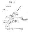
- Fig. 2 shows the intake manifold pressure P and the flow rate QA in the main path 16 obtained when both the throttle valve 18 and the bypass valve 34 are changed.
- the engine speed N is assumed to be constant.
- the characteristic associated with the closed-up bypass valve 34 and the characteristic of the full-open bypass valve 34 are shown by 8BC and 8BO respectively.
- the intake manifold pressure is more proximate the atmospheric pressure when the bypass valve is full open than when it is closed up.
- the intake manifold pressure assumes a characteristic corresponding to the opening 8B between ⁇ BO and 6BC.
- the upstream of the throttle valve 18 is substantially at the atmospheric pressure, and the pressure between upstream and downstream of the throttle valve 18 takes a value of the difference PB with the atmospheric pressure.
- the intake manifold pressure PBC associated with such saturation will hereinafter be referred to as the critical pressure.
- the critical pressure At an intake manifold pressure lower than the critical pressure PBC, the flow velocity is determined regardless of the intake manifold pressure and therefore the flow rate of the main path QA depends solely on the opening of the throttle 18.
- the flow rate in the main path 16 is determined by the opening of the throttle 18 and the pressure difference PB. Since the intake manifold pressure changes with the opening of the bypass valve 34 as described above, the flow rate QA of the main path also varies with the opening of the bypass valve as shown by the hatched part in the graph.
- the flow rate of the bypass for the closed-up state of the bypass valve 34 is designated by QAC, while the flow rate of the main path for the full open state of the bypass valve is indicated by QAO.
- the flow rate of the main path assumes a characteristic between QAC and QAO in accordance with the opening involved.
- the flow rate of the main path 16 is reduced along the characteristic shown by the hatched part.
- the fact that the flow rate of the main path is reduced in accordance with the opening of the bypass valve 34 reduces the fuel supply as compared with the amount of drive operation, thus reducing the torque generated.
- the resulting decrease in the torque as compared with the amount of driver operation necessitates the value ⁇ TI for compensation for torque reduction.
- the correction ⁇ TI is thus computed on the basis of equation (4) thereby to increase the fuel amount.
- a fuel computation flowchart is shown in Fig. 3.
- the engine speed N and the air amount QA are introduced as parameters.
- the basic fuel supply amount TP is computed from the engine speed N and the air amount QA, . followed by step 316 for reading the correction factor K1 from the table.
- This correction factor K1 is determined in accordance with the water temperature, acceleration, deceleration, etc. The computation involved is well known.
- Step 318 reads out the bypass valve opening ⁇ B computed from equation (2) in a separate flowchart in response to the throttle opening ⁇ TH and the engine speed N.
- Step 320 retrieves the correction ⁇ TI from the look-up table stored in memory with the throttle valve opening ⁇ TH and the bypass valve opening ⁇ B as parameters.
- Step 322 is for computing the fuel supply from equation (3) and producing the same.
- the injector in Fig. 1 supplies fuel to the engine on the basis of the result of this computation.
- the correction ⁇ TI is determined from parameters ⁇ TH and ⁇ B in the embodiment under consideration, the engine speed N may be added for an improved accuracy. This is made possible by providing a read-only-memory for storing a second look-up table with the engine speed N and the result of retrieval at step 320 as parameters and retrieving the table by the detected parameters.
- a predetermined air-fuel ratio is obtained.
- the change of a target air-fuel ratio with the opening of the throttle valve 18 changes from closed to open state is shown in Fig. 4.
- the lean mixture gas operation is performed in the throttle opening range from 81 to 82.
- This operating range represents the start and a run such as on a flat road, while the range from 82 to 83 represents a run on a gentle slope or a high speed operation.
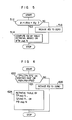
- the control flow involved is shown in Fig. 5.
- Step 512 decides whether or not the opening of the throttle valve 18 is between 01 and 82, and if so, the process proceeds to step 514.
- the bypass valve opening 6B is retrieved and produced from the look-up table held in the read-only-memory with the throttle valve opening 8Th and engine speed N as parameters.
- a pulse motor is for controlling the bypass valve 34 and supplying air to the engine in response to the control signal ⁇ B. If the operating conditions are different and the throttle opening fails to satisfy the conditions of step 512, then the control signal ⁇ B is produced for reducing the opening of the bypass valve 34 to zero.
- the control signal 6B is stored in memory to permit the use of ⁇ B in the flowchart of Fig. 3.
- the opening of the bypass valve is controlled in accordance with the opening of the throttle valve which is the amount of driver operation.
- the lean mixture gas control conforming to the feeling of the driver is performed, thus facilitating the driving operation.
- Fig. 6 shows an embodiment different from that of Fig. 5.
- the basic fuel amount TP instead of the throttle valve opening ⁇ TH used at step 512 of Fig. 5, the basic fuel amount TP, the air amount QA in the main path or the negative pressure PM of the intake manifold may be used.
- the basic fuel amount is determined by the equation below from the air amount QA and the engine speed N.
- the equation (6) below may be used taking the correction of K1 in equation (3) into consideration.
- QA When QA is used as a parameter, it is detected as an output of the air flowmeter.
- the negative pressure PM if used as a parameter, may be detected by a negative pressure sensor mounted in the downstream of the throttle 18 such as at a point M in Fig. 1.
- decision is made as to whether or not the lean mixture gas control range is involved in the same manner as at step 512, and if the lean mixture gas control range is involved, the process is passed to step 624. If the lean mixture gas control range is not involved, by contrast, the process proceeds to step 626 to reduce the bypass valve opening 8B to zero.
- Step 624 retrieves as an input a required parameter from the look-up table on the basis of parameters TP and N, QA and N, or PB and N, and produces the bypass valve opening 8B as an output.
- This bypass valve opening 8B is stored for use in the flowchart of Fig. 3 on the one hand and is produced for controlling the pulse motor 36 on the other hand.
- the lean mixture gas control operation is possible in accordance with the parameters TP, QA and PM providing the actual load data of the engine, thereby permitting a reasonable control in response to the engine operation.
- a system may be provided without a throttle opening sensor, in which case the control shown in Fig. 6 is naturally employed with a lower system cost by the elimination of the throttle opening sensor.
- the throttle valve opening OTH, the basic fuel supply amount TP, the air intake QA of the main path or the intake manifold negative pressure PM is used as a parameter PR to produce a smooth engine torque characteristic T in accordance with the fuel supply TI as shown by the solid line in Fig. 7.
- the dotted curve in Fig. 7 represents a torque change obtained when the present invention is not applied.
- the abscissa in Fig. 7 may indicate not 8TH but another load data such as 8A, TP or PM.
- the lean mixture gas operation range is selected as desired on the basis of the engine characteristics, thus achieving superior control characteristics.
- the output signal of the sensor ES is used to control the bypass valve 34 and/or the fuel injection valve 40 by feedback as shown in Figs. 1 and 8.
- the air-fuel ratio is controlled to about 14.7 against the air amount of the main path 16 for the throttle valve opening between 81 and 82, so that the solenoid valve 64 is also supplied with a control signal associated with the air-fuel ratio of about 14.7.
- the opening of the bypass valve 34 may be computed by the flowchart of Fig. 5. With an increase of the opening of the bypass valve 34, the amount of air in the main path 16 decreases as explained with reference to the hatched portion in Fig. 2, thus reducing the fuel supply amount relatively. In orderto prevent this inconvenience, it is necessary to increase the fuel in accordance with the opening 8B of the bypass valve 34 by the control signal applied to the solenoid valve 62.
- the range of correction by increased fuel amount is the one associated with the air flow velocity in the throttle valve lower than the sound velocity as in the case using the injector.
- Fig. 8 uses the throttle valve opening as a parameter and the flowchart of Fig. 5 for determining the bypass valve opening, the manifold pressure PM may be used as an additional parameter.
- the supplied fuel changes with the negative pressure of the venturi 60, resulting in a higher response under transient operating conditions. Further, since the fuel is supplied in accordance with the amount of driver operation as in the above-mentioned embodiments, the torque corresponding to the amount of driver operation is generated. Furthermore the fact that the lean mixture gas operation is possible permits the consumed fuel to be converted into torque at high efficiency.
Landscapes
- Engineering & Computer Science (AREA)
- Chemical & Material Sciences (AREA)
- Combustion & Propulsion (AREA)
- Mechanical Engineering (AREA)
- General Engineering & Computer Science (AREA)
- Electrical Control Of Air Or Fuel Supplied To Internal-Combustion Engine (AREA)
- Output Control And Ontrol Of Special Type Engine (AREA)
Claims (7)
Applications Claiming Priority (2)
| Application Number | Priority Date | Filing Date | Title |
|---|---|---|---|
| JP57181283A JPS5970853A (ja) | 1982-10-18 | 1982-10-18 | 自動車用エンジンの制御装置 |
| JP181283/82 | 1982-10-18 |
Publications (3)
| Publication Number | Publication Date |
|---|---|
| EP0106348A2 EP0106348A2 (de) | 1984-04-25 |
| EP0106348A3 EP0106348A3 (en) | 1985-12-11 |
| EP0106348B1 true EP0106348B1 (de) | 1989-01-11 |
Family
ID=16097979
Family Applications (1)
| Application Number | Title | Priority Date | Filing Date |
|---|---|---|---|
| EP83110340A Expired EP0106348B1 (de) | 1982-10-18 | 1983-10-17 | Methode um das Luft-Kraftstoff-Verhältnis der Innenbrennkraftmaschinen von Fahrzeugen zu steuern |
Country Status (5)
| Country | Link |
|---|---|
| US (1) | US4616621A (de) |
| EP (1) | EP0106348B1 (de) |
| JP (1) | JPS5970853A (de) |
| KR (1) | KR880001684B1 (de) |
| DE (1) | DE3378922D1 (de) |
Cited By (1)
| Publication number | Priority date | Publication date | Assignee | Title |
|---|---|---|---|---|
| DE19505687A1 (de) * | 1995-02-20 | 1996-08-22 | Audi Ag | Verfahren zur Steuerung einer Brennkraftmaschine im Sekundärluftbetrieb |
Families Citing this family (31)
| Publication number | Priority date | Publication date | Assignee | Title |
|---|---|---|---|---|
| JPS61167134A (ja) * | 1985-01-18 | 1986-07-28 | Mazda Motor Corp | エンジンの空燃比制御装置 |
| JPH0621594B2 (ja) * | 1985-02-15 | 1994-03-23 | 三菱自動車工業株式会社 | 車両用エンジンの空燃比制御装置 |
| JPS61187560A (ja) * | 1985-02-15 | 1986-08-21 | Diesel Kiki Co Ltd | 燃料噴射時期制御方法 |
| JPH0663461B2 (ja) * | 1985-09-03 | 1994-08-22 | トヨタ自動車株式会社 | 内燃機関の燃料噴射制御装置 |
| JPS6278447A (ja) * | 1985-10-02 | 1987-04-10 | Mitsubishi Electric Corp | 内燃機関の燃料噴射制御装置 |
| DE3634015A1 (de) * | 1985-10-05 | 1987-04-09 | Honda Motor Co Ltd | Luftansaugseitige sekundaerluftversorgungsvorrichtung fuer eine brennkraftmaschine |
| JPS62165544A (ja) * | 1986-01-17 | 1987-07-22 | Mazda Motor Corp | エンジンの空燃比制御装置 |
| JPH0733803B2 (ja) * | 1986-04-30 | 1995-04-12 | マツダ株式会社 | 電子燃料噴射エンジンの燃料制御装置 |
| US4796591A (en) * | 1986-09-03 | 1989-01-10 | Nippondenso Co., Ltd. | Internal combustion engine control system |
| JPS6394039A (ja) * | 1986-10-08 | 1988-04-25 | Hitachi Ltd | 内燃機関の燃料制御方法及び装置 |
| US5224044A (en) * | 1988-02-05 | 1993-06-29 | Nissan Motor Company, Limited | System for controlling driving condition of automotive device associated with vehicle slip control system |
| JPH01224424A (ja) * | 1988-03-03 | 1989-09-07 | Nippon Denso Co Ltd | 内燃機関の制御装置 |
| US4951773A (en) * | 1989-07-25 | 1990-08-28 | General Motors Corporation | Vehicle traction control system with fuel control |
| US4932371A (en) * | 1989-08-14 | 1990-06-12 | General Motors Corporation | Emission control system for a crankcase scavenged two-stroke engine operating near idle |
| US5121724A (en) * | 1989-11-16 | 1992-06-16 | Nissan Motor Company, Ltd. | Multi-cylinder internal combustion engine with individual port throttles upstream of intake valves |
| US5129381A (en) * | 1990-06-18 | 1992-07-14 | Nissan Motor Co., Ltd. | Fuel injection system for internal combustion engine |
| DE4031002A1 (de) * | 1990-10-01 | 1992-04-02 | Vdo Schindling | Lastverstelleinrichtung |
| JPH0681719A (ja) * | 1992-08-31 | 1994-03-22 | Hitachi Ltd | 内燃機関の吸気装置 |
| DE4418112B4 (de) * | 1993-06-01 | 2009-08-27 | Volkswagen Ag | Verfahren zum Betreiben einer Brennkraftmaschine, die zur Verbrennung eines Gemischs mit hohem Luftverhältnis ausgelegt ist |
| DE4447873B4 (de) * | 1993-12-28 | 2010-07-15 | Mitsubishi Jidosha Kogyo K.K. | Regelungsvorrichtung und Regelungsverfahren für Magerverbrennungsmotor |
| JPH07189875A (ja) * | 1993-12-28 | 1995-07-28 | Yamaha Motor Co Ltd | 2サイクルエンジンの燃料噴射装置 |
| DE4416611A1 (de) * | 1994-05-11 | 1995-11-16 | Bosch Gmbh Robert | Verfahren und Vorrichtung zur Steuerung einer Brennkraftmaschine |
| EP0687809B1 (de) * | 1994-06-17 | 2001-08-29 | Hitachi, Ltd. | Ausgangsdrehmoment-Steuerungsvorrichtung und Verfahren für eine Brennkraftmaschine |
| JPH0835438A (ja) | 1994-07-25 | 1996-02-06 | Hitachi Ltd | エンジンパワートレインの制御方法 |
| JP3018959B2 (ja) * | 1995-09-11 | 2000-03-13 | 日立建機株式会社 | 建設機械のワイパ作動制御装置 |
| US5787380A (en) * | 1995-10-27 | 1998-07-28 | Ford Global Technologies, Inc. | Air/fuel control including lean cruise operation |
| KR100318836B1 (ko) * | 1996-08-28 | 2002-02-19 | 나까무라히로까즈 | 기통내분사내연기관의제어장치 |
| JPH10157492A (ja) * | 1996-11-29 | 1998-06-16 | Hitachi Ltd | 無段自動変速機の制御装置 |
| DE19728798C2 (de) * | 1997-07-05 | 2003-10-30 | Ford Global Tech Inc | Verfahren zur Steuerung der Ansaugluftmenge eines Verbrennungsmotors |
| SE529324C2 (sv) * | 2005-04-04 | 2007-07-03 | Lars Svensson Med Odena Engine | System för att styra luft/bränsleförhållande i en luft/bränsleblandning som matas till en brännare för förblandade bränslen |
| JP4996567B2 (ja) * | 2008-09-11 | 2012-08-08 | 大阪瓦斯株式会社 | エンジン |
Citations (1)
| Publication number | Priority date | Publication date | Assignee | Title |
|---|---|---|---|---|
| FR2135996A5 (de) * | 1971-04-02 | 1972-12-22 | Bosch Gmbh Robert |
Family Cites Families (9)
| Publication number | Priority date | Publication date | Assignee | Title |
|---|---|---|---|---|
| US4153021A (en) * | 1973-06-04 | 1979-05-08 | Nippon Soken, Inc. | Air-fuel mixture ratio correcting system for carburetor |
| JPS5834658B2 (ja) * | 1975-11-11 | 1983-07-28 | カブシキガイシヤ ニツポンジドウシヤブヒンソウゴウケンキユウシヨ | クウキリユウリヨウチヨウセイソウチ |
| US4106451A (en) * | 1976-04-13 | 1978-08-15 | Nippon Soken, Inc. | Air-fuel ratio adjusting system for internal combustion engines |
| US4240145A (en) * | 1977-12-01 | 1980-12-16 | Nissan Motor Company, Limited | Closed loop controlled auxiliary air delivery system for internal combustion engine |
| JPS5596350A (en) * | 1979-01-16 | 1980-07-22 | Hitachi Ltd | Method of controlling internal combustion engine in terms of numerous variables |
| JPS55148927A (en) * | 1979-05-09 | 1980-11-19 | Hitachi Ltd | Air-fuel ratio controller |
| US4442818A (en) * | 1980-12-29 | 1984-04-17 | Hitachi, Ltd. | Fuel injection apparatus for internal combustion engines |
| DE3120667A1 (de) * | 1981-05-23 | 1982-12-16 | Robert Bosch Gmbh, 7000 Stuttgart | Steuersystem fuer eine fremdgezuendete brennkraftmaschine |
| JPS5862333A (ja) * | 1981-10-09 | 1983-04-13 | Mazda Motor Corp | エンジンのアイドル回転制御装置 |
-
1982
- 1982-10-18 JP JP57181283A patent/JPS5970853A/ja active Pending
-
1983
- 1983-10-14 KR KR1019830004871A patent/KR880001684B1/ko not_active Expired
- 1983-10-17 EP EP83110340A patent/EP0106348B1/de not_active Expired
- 1983-10-17 DE DE8383110340T patent/DE3378922D1/de not_active Expired
- 1983-10-18 US US06/542,994 patent/US4616621A/en not_active Expired - Fee Related
Patent Citations (1)
| Publication number | Priority date | Publication date | Assignee | Title |
|---|---|---|---|---|
| FR2135996A5 (de) * | 1971-04-02 | 1972-12-22 | Bosch Gmbh Robert |
Cited By (1)
| Publication number | Priority date | Publication date | Assignee | Title |
|---|---|---|---|---|
| DE19505687A1 (de) * | 1995-02-20 | 1996-08-22 | Audi Ag | Verfahren zur Steuerung einer Brennkraftmaschine im Sekundärluftbetrieb |
Also Published As
| Publication number | Publication date |
|---|---|
| EP0106348A3 (en) | 1985-12-11 |
| US4616621A (en) | 1986-10-14 |
| DE3378922D1 (en) | 1989-02-16 |
| EP0106348A2 (de) | 1984-04-25 |
| KR840007141A (ko) | 1984-12-05 |
| JPS5970853A (ja) | 1984-04-21 |
| KR880001684B1 (ko) | 1988-09-06 |
Similar Documents
| Publication | Publication Date | Title |
|---|---|---|
| EP0106348B1 (de) | Methode um das Luft-Kraftstoff-Verhältnis der Innenbrennkraftmaschinen von Fahrzeugen zu steuern | |
| US5727528A (en) | Control apparatus and control method of internal combustion engine | |
| US5009210A (en) | Air/fuel ratio feedback control system for lean combustion engine | |
| US4545348A (en) | Idle speed control method and system for an internal combustion engine | |
| EP0053464A2 (de) | Elektronisch gesteuertes Kraftstoffeinspritzsystem | |
| KR930011555B1 (ko) | 내연기관의 드로틀밸브개방도 제어장치 | |
| US5195497A (en) | Method for detecting fuel blending ratio | |
| JPS60240840A (ja) | 内燃機関の空燃比制御装置 | |
| US4895125A (en) | Apparatus for the feedback of exhaust gases in an internal combustion engine | |
| JP3063400B2 (ja) | 内燃エンジンの空燃比制御装置 | |
| JPH1182090A (ja) | 内燃機関の制御装置 | |
| US5197451A (en) | Method for detecting fuel blending ratio | |
| JPWO1993002281A1 (ja) | 内燃エンジンの空燃比制御装置 | |
| US5282450A (en) | Engine power controller | |
| JPH0689686B2 (ja) | エンジンの空燃比制御装置 | |
| JP2000136745A (ja) | エンジンの空燃比制御装置 | |
| JPS61126336A (ja) | エンジンのスロツトル弁制御装置 | |
| JP3428693B2 (ja) | 気体燃料機関における気体燃料の混合気供給装置 | |
| JPH0455234Y2 (de) | ||
| JPH0243900B2 (ja) | Nainenkikannogakushuseigyosochi | |
| JPH03490B2 (de) | ||
| JPS61126346A (ja) | エンジンのスロツトル弁制御装置 | |
| JPS6189944A (ja) | エンジンのスロツトル弁制御装置 | |
| JPH0587660B2 (de) | ||
| JPH0536614B2 (de) |
Legal Events
| Date | Code | Title | Description |
|---|---|---|---|
| PUAI | Public reference made under article 153(3) epc to a published international application that has entered the european phase |
Free format text: ORIGINAL CODE: 0009012 |
|
| AK | Designated contracting states |
Designated state(s): DE FR GB IT |
|
| PUAL | Search report despatched |
Free format text: ORIGINAL CODE: 0009013 |
|
| AK | Designated contracting states |
Designated state(s): DE FR GB IT |
|
| 17P | Request for examination filed |
Effective date: 19851213 |
|
| 17Q | First examination report despatched |
Effective date: 19861112 |
|
| GRAA | (expected) grant |
Free format text: ORIGINAL CODE: 0009210 |
|
| AK | Designated contracting states |
Kind code of ref document: B1 Designated state(s): DE FR GB IT |
|
| REF | Corresponds to: |
Ref document number: 3378922 Country of ref document: DE Date of ref document: 19890216 |
|
| ET | Fr: translation filed | ||
| ITF | It: translation for a ep patent filed | ||
| ITTA | It: last paid annual fee | ||
| PLBE | No opposition filed within time limit |
Free format text: ORIGINAL CODE: 0009261 |
|
| STAA | Information on the status of an ep patent application or granted ep patent |
Free format text: STATUS: NO OPPOSITION FILED WITHIN TIME LIMIT |
|
| 26N | No opposition filed | ||
| PGFP | Annual fee paid to national office [announced via postgrant information from national office to epo] |
Ref country code: GB Payment date: 19910808 Year of fee payment: 9 |
|
| PGFP | Annual fee paid to national office [announced via postgrant information from national office to epo] |
Ref country code: FR Payment date: 19910918 Year of fee payment: 9 |
|
| PG25 | Lapsed in a contracting state [announced via postgrant information from national office to epo] |
Ref country code: GB Effective date: 19921017 |
|
| GBPC | Gb: european patent ceased through non-payment of renewal fee |
Effective date: 19921017 |
|
| PG25 | Lapsed in a contracting state [announced via postgrant information from national office to epo] |
Ref country code: FR Effective date: 19930630 |
|
| REG | Reference to a national code |
Ref country code: FR Ref legal event code: ST |
|
| PGFP | Annual fee paid to national office [announced via postgrant information from national office to epo] |
Ref country code: DE Payment date: 20011230 Year of fee payment: 19 |
|
| PG25 | Lapsed in a contracting state [announced via postgrant information from national office to epo] |
Ref country code: DE Free format text: LAPSE BECAUSE OF NON-PAYMENT OF DUE FEES Effective date: 20030501 |