EP0106331A2 - Procédé et dispositif pour la séparation des particules grossières d'un liquide - Google Patents
Procédé et dispositif pour la séparation des particules grossières d'un liquide Download PDFInfo
- Publication number
- EP0106331A2 EP0106331A2 EP83110256A EP83110256A EP0106331A2 EP 0106331 A2 EP0106331 A2 EP 0106331A2 EP 83110256 A EP83110256 A EP 83110256A EP 83110256 A EP83110256 A EP 83110256A EP 0106331 A2 EP0106331 A2 EP 0106331A2
- Authority
- EP
- European Patent Office
- Prior art keywords
- liquid
- screen cloth
- nozzle
- container
- air
- Prior art date
- Legal status (The legal status is an assumption and is not a legal conclusion. Google has not performed a legal analysis and makes no representation as to the accuracy of the status listed.)
- Ceased
Links
Images

Classifications
-
- D—TEXTILES; PAPER
- D21—PAPER-MAKING; PRODUCTION OF CELLULOSE
- D21D—TREATMENT OF THE MATERIALS BEFORE PASSING TO THE PAPER-MAKING MACHINE
- D21D5/00—Purification of the pulp suspension by mechanical means; Apparatus therefor
- D21D5/02—Straining or screening the pulp
- D21D5/04—Flat screens
-
- B—PERFORMING OPERATIONS; TRANSPORTING
- B01—PHYSICAL OR CHEMICAL PROCESSES OR APPARATUS IN GENERAL
- B01D—SEPARATION
- B01D29/00—Filters with filtering elements stationary during filtration, e.g. pressure or suction filters, not covered by groups B01D24/00 - B01D27/00; Filtering elements therefor
- B01D29/01—Filters with filtering elements stationary during filtration, e.g. pressure or suction filters, not covered by groups B01D24/00 - B01D27/00; Filtering elements therefor with flat filtering elements
-
- B—PERFORMING OPERATIONS; TRANSPORTING
- B01—PHYSICAL OR CHEMICAL PROCESSES OR APPARATUS IN GENERAL
- B01D—SEPARATION
- B01D29/00—Filters with filtering elements stationary during filtration, e.g. pressure or suction filters, not covered by groups B01D24/00 - B01D27/00; Filtering elements therefor
- B01D29/88—Filters with filtering elements stationary during filtration, e.g. pressure or suction filters, not covered by groups B01D24/00 - B01D27/00; Filtering elements therefor having feed or discharge devices
- B01D29/90—Filters with filtering elements stationary during filtration, e.g. pressure or suction filters, not covered by groups B01D24/00 - B01D27/00; Filtering elements therefor having feed or discharge devices for feeding
- B01D29/902—Filters with filtering elements stationary during filtration, e.g. pressure or suction filters, not covered by groups B01D24/00 - B01D27/00; Filtering elements therefor having feed or discharge devices for feeding containing fixed liquid displacement elements or cores
-
- B—PERFORMING OPERATIONS; TRANSPORTING
- B01—PHYSICAL OR CHEMICAL PROCESSES OR APPARATUS IN GENERAL
- B01D—SEPARATION
- B01D29/00—Filters with filtering elements stationary during filtration, e.g. pressure or suction filters, not covered by groups B01D24/00 - B01D27/00; Filtering elements therefor
- B01D29/88—Filters with filtering elements stationary during filtration, e.g. pressure or suction filters, not covered by groups B01D24/00 - B01D27/00; Filtering elements therefor having feed or discharge devices
- B01D29/90—Filters with filtering elements stationary during filtration, e.g. pressure or suction filters, not covered by groups B01D24/00 - B01D27/00; Filtering elements therefor having feed or discharge devices for feeding
- B01D29/904—Filters with filtering elements stationary during filtration, e.g. pressure or suction filters, not covered by groups B01D24/00 - B01D27/00; Filtering elements therefor having feed or discharge devices for feeding directing the mixture to be filtered on the filtering element in a manner to clean the filter continuously
Definitions
- the invention relates to a method for separating coarse particles from a liquid according to the preamble of claim 1 and an apparatus for performing the method, which has the features listed in the preamble of claim 4.
- a liquid containing coarse and fine particles e.g. Water
- these particles include from coarse and fine fibers.
- the liquid comes from washing machines and contains fine fibers, lint and the like. as well as coarser components.
- the liquid level in the container is kept at a constant level below the nozzle, so that it is in a closed air space between the screen cloth and the liquid surface.
- the liquid level is kept constant by means of an overflow and this liquid must then be cleaned of the coarser particles before it can be used further.
- additional energy has to be used in the treatment of this liquid, the amount of which is 15-30% of the amount conveyed by the pump.
- the invention has for its object to largely avoid these disadvantages of the known devices, which is achieved according to the invention with the means that form the characterizing features of claim 1 and claim 4.
- Advantageous embodiments of the method and the device form the subject of the subclaims.
- the liquid can only flow out of the container through the screen cloth.
- the liquid passing through the screen cloth in one time unit is thus equal to the total liquid conveyed by the pump in the unit time, so that the disadvantages associated with the known devices with the partial flow flowing off via the overflow are completely avoided.
- the coarse particles slowly sink to the bottom of the container and accumulate there, so that they can be removed from the container quickly and easily from time to time by placing one on the bottom of the container Separation valve is opened for a short time.
- washing systems considerable advantages are achieved since no hot water flows out of the container, but rather all of the water flows through the screen cloth and can thus give off its heat to the heat exchanger.
- the suction line of the pump is advantageously connected to an air line in which a regulating valve is arranged, so that more or less air can be sucked into the liquid conveyed by the pump.
- This additional air then relaxes in the air space underneath the screen cloth and influences the air pressure in this space and thus also the level of the liquid in the container.
- the liquid conveyed by the pump usually contains a small amount of air, which also relaxes during the spraying process and thus additionally increases the air pressure in the space under the screen cloth.
- a guide cone is arranged at a distance from the nozzle, so that the preferably hollow conical liquid jet passes through a liquid layer which is located in the gap between the nozzle and the lower boundary of the guide cone. The formation of the liquid jet is thus maintained by the guide cone up to its upper end and beyond until it hits the screen cloth.
- the level of the container liquid thus extends up to a certain height on the outer surface of the guide cone. Practical tests have shown that with the arrangement of this guide cone i.a. stable operation with a constant liquid level is achieved.
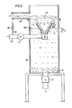
- the liquid, the coarse and fine particles such as Contains fibers of different sizes, the container 14 is fed through a line 10.
- the liquid usually also contains a certain amount of air.
- a pump 11 is arranged in line 10, the delivery pressure of which can be regulated in the usual way.
- the pump 11 conveys the liquid to a nozzle 12 of a known embodiment, which sprays the liquid into a conical jet 13, which should expediently be hollow.
- the nozzle 12 is arranged in a vertical container 14 which has an intermediate wall in the form of a screen cloth 15 in its upper region.
- the mesh size of the screen cloth can be in a range of 10-100 ⁇ m and is usually in the lower range.
- An outlet connection 16 is arranged above the screen cloth 15, which is penetrated by the liquid together with fine particles.
- the liquid is sprayed upwards against the underside of the screen cloth 15, the coarser particles impinging on the screen cloth and falling down from it in the container, in whose liquid they sink down and collect on the bottom 17 thereof.
- the liquid is held in the container 14 at a substantially constant height 18, the liquid level being at a distance H above the outlet opening of the nozzle 12 shown in FIG. 1, so that the conical liquid jet passes through a liquid layer of appropriate thickness without its conical one Losing shape.
- the liquid located in the vicinity of the nozzle 12 is sucked into the liquid jet so that a larger amount of liquid is sprayed against the screen cloth 15 than is conveyed by the pump 11. For example, if the pump delivers 100 liters per minute, 120 liters per minute can be sprayed against the screen cloth 15, with 100 liters per minute flowing through the screen cloth 15 and the outlet port 16, while 20 liters per minute flow back from the screen cloth and mix with the liquid jet of the nozzle 12 and are sprayed again against the screen cloth 15. The larger amount of liquid sprayed against the screen cloth 15 thus leads to more stable and quieter operating conditions.
- the rough adjustment of the liquid level is carried out by regulating the pump pressure.
- a fine adjustment is made by introducing more or less additional air into the suction line of the pump 11.
- the suction line 10 of the pump 11 is connected to an air line 19, so that air 19 can be sucked in through this line, the desired amount of which can be finely adjusted by means of the regulating valve 20.
- a guide surface 22 is provided in the container 14 in the form of a truncated cone, the cone angle of which is approximately the same as that of the liquid jet sprayed by the nozzle 12.
- This conical guide surface is arranged coaxially with the nozzle 12 above it with its conically tapering end pointing downwards, so that the conical liquid jet enters this guide cone and is guided within this guide cone until it flows past the upper end of the guide cone onto the screen cloth 15 hits.
- the upper end of the guide cone is located approximately halfway between the nozzle 12 and the screen cloth 15 or somewhat higher.
- the liquid level 18A in the container 14 is somewhat higher than in the exemplary embodiment shown in FIG. 1, since it is at a greater height than the gap between the nozzle 12 and the guide cone 22. In this case, the liquid level is at a height H2 above the nozzle opening.
- An outlet valve 21 is provided on the bottom of the container 14 in order to be able to pull off the coarse particles which have accumulated on the bottom of the container from time to time. In certain cases it is sufficient to remove the coarse particles only once during 24 hours.
- the branched-off liquid flow in the previously known devices, can be up to approximately 15-30% of the total flow. In water purification systems, for example, this means that the branched-off water flow also has to be cleaned in order to achieve a perfect cleaning effect. However, this is not necessary in the device according to the invention, since 100% of the total liquid flow passes through the screen cloth 15 and flows out through the outlet connection 16. For a given current passing through the screen cloth 15, the method and the device according to the invention can use a pump with a lower delivery rate than is required in the known devices.
Landscapes
- Chemical & Material Sciences (AREA)
- Chemical Kinetics & Catalysis (AREA)
- Engineering & Computer Science (AREA)
- Mechanical Engineering (AREA)
- Treatment Of Fiber Materials (AREA)
- Separation Of Solids By Using Liquids Or Pneumatic Power (AREA)
- Application Of Or Painting With Fluid Materials (AREA)
- Paper (AREA)
Applications Claiming Priority (2)
| Application Number | Priority Date | Filing Date | Title |
|---|---|---|---|
| SE8205961 | 1982-10-20 | ||
| SE8205961A SE433706B (sv) | 1982-10-20 | 1982-10-20 | Sett och apparat for att fran en vetska avskilja grovre partiklar |
Publications (2)
| Publication Number | Publication Date |
|---|---|
| EP0106331A2 true EP0106331A2 (fr) | 1984-04-25 |
| EP0106331A3 EP0106331A3 (fr) | 1985-05-02 |
Family
ID=20348280
Family Applications (1)
| Application Number | Title | Priority Date | Filing Date |
|---|---|---|---|
| EP83110256A Ceased EP0106331A3 (fr) | 1982-10-20 | 1983-10-14 | Procédé et dispositif pour la séparation des particules grossières d'un liquide |
Country Status (7)
| Country | Link |
|---|---|
| US (1) | US4536295A (fr) |
| EP (1) | EP0106331A3 (fr) |
| JP (1) | JPS5992042A (fr) |
| AU (1) | AU2017683A (fr) |
| CA (1) | CA1212649A (fr) |
| FI (1) | FI71670C (fr) |
| SE (1) | SE433706B (fr) |
Families Citing this family (2)
| Publication number | Priority date | Publication date | Assignee | Title |
|---|---|---|---|---|
| GB2245842A (en) * | 1990-07-13 | 1992-01-15 | Patrick Joseph Tierney | Cross-flow filter |
| JP2014161803A (ja) * | 2013-02-26 | 2014-09-08 | Natsuo Inagaki | 吸引洗浄装置 |
Family Cites Families (7)
| Publication number | Priority date | Publication date | Assignee | Title |
|---|---|---|---|---|
| US518238A (en) * | 1894-04-17 | Alwin georg eugen fullmer | ||
| DE287886C (fr) * | ||||
| US1512323A (en) * | 1923-10-08 | 1924-10-21 | Halbert C Wallace | Grain cleaner |
| US3789978A (en) * | 1971-04-20 | 1974-02-05 | B Janson | Method and apparatus for separating finer particles from coarse particles suspended in a liquid |
| SE402942B (sv) * | 1976-11-30 | 1978-07-24 | Ljungstrom Eva Kristina | Fraktioneringsapparat |
| JPS55114394A (en) * | 1979-02-24 | 1980-09-03 | Eiichi Sugiura | Water suction pipe air intake type vapor-liquid mixing pressure aerator for polluted water treatment |
| SE435454B (sv) * | 1979-08-21 | 1984-10-01 | Uk N Proizv Ob Tsellju | Anordning for avskiljning av fiberinneslutningar fran industriavloppsvatten |
-
1982
- 1982-10-20 SE SE8205961A patent/SE433706B/sv not_active IP Right Cessation
-
1983
- 1983-10-13 US US06/541,736 patent/US4536295A/en not_active Expired - Fee Related
- 1983-10-14 EP EP83110256A patent/EP0106331A3/fr not_active Ceased
- 1983-10-14 AU AU20176/83A patent/AU2017683A/en not_active Abandoned
- 1983-10-19 CA CA000439292A patent/CA1212649A/fr not_active Expired
- 1983-10-19 JP JP58194453A patent/JPS5992042A/ja active Pending
- 1983-10-20 FI FI833838A patent/FI71670C/fi not_active IP Right Cessation
Also Published As
| Publication number | Publication date |
|---|---|
| FI833838A0 (fi) | 1983-10-20 |
| SE433706B (sv) | 1984-06-12 |
| US4536295A (en) | 1985-08-20 |
| SE8205961L (sv) | 1984-04-21 |
| SE8205961D0 (sv) | 1982-10-20 |
| FI71670B (fi) | 1986-10-31 |
| JPS5992042A (ja) | 1984-05-28 |
| CA1212649A (fr) | 1986-10-14 |
| EP0106331A3 (fr) | 1985-05-02 |
| FI833838L (fi) | 1984-04-21 |
| FI71670C (fi) | 1987-02-09 |
| AU2017683A (en) | 1984-05-03 |
Similar Documents
| Publication | Publication Date | Title |
|---|---|---|
| DE2032824C2 (de) | Verfahren und Vorrichtung zur Abscheidung von festen Farb- und Schmutzteilchen aus einer Waschflüssigkeit | |
| DE69704120T2 (de) | Verfahren und vorrichtung zum reinigen einer schmutzigen oberfläche | |
| DE69612366T2 (de) | Verfahren und gerät zur herstellung von mit luft gesättigtem wasser | |
| DE69109668T2 (de) | Methode und gerät zum filtern einer teilchenflüssigkeitssuspension. | |
| DE2835709A1 (de) | Verfahren und vorrichtung zum loesen von luft in wasser und anschliessendes entspannen des wassers in flotationsanlagen | |
| DE3931680A1 (de) | Einrichtung zum absaugen von fluessigkeiten | |
| EP0162874B1 (fr) | Installation de purification et de separation pour melanges d'huile et de matieres solides | |
| DE2914392C2 (de) | Verfahren und Vorrichtung zum Deinken von Faserstoffsuspensionen | |
| EP0106331A2 (fr) | Procédé et dispositif pour la séparation des particules grossières d'un liquide | |
| DE2417580A1 (de) | Verfahren und vorrichtung zum richten eines feste abriebpartikel enhaltenden fluessigkeitsstrahls auf die oberflaeche eines werkstuecks | |
| DE2117931C3 (de) | Verfahren und Vorrichtung zum Trennen von in einer Flüssigkeit vorhandenen Teilchen unterschiedlicher Größe | |
| DE2442677A1 (de) | Verfahren und vorrichtung zur luftreinigung beim farbspritzen | |
| DE720362C (de) | Einrichtung zum Klaeren der Abwaesser der Zellstoff-, Holzstoff-, Papier- und Pappenfabrikation | |
| DE8702677U1 (de) | Vorrichtung zum Aufbereiten eines Lackschlamm-Wassergemisches | |
| DE402853C (de) | Verfahren und Einrichtung zum Klaeren von Kalkmilch | |
| DE634152C (de) | Paternosterartige Vorrichtung zum kontinuierlichen Extrahieren | |
| DE950150C (de) | Vorrichtung zum Reinigen von aus Samen oder Nuessen gewonnenen OElen oder Fetten | |
| AT165093B (de) | Kalksättiger für die Wasserreinigung | |
| DE3107899A1 (de) | "filter zur entfernung von feststoffen aus fluessigkeiten" | |
| DE823095C (de) | Verfahren und Vorrichtung zum Entgasen von luftbehafteten Papierfaserstoffaufschwemmungen | |
| DE535604C (de) | Verfahren und Einrichtung zum Loeschen von Kalk oder aehnlichen, Staub entwickelnden Stoffen | |
| AT166616B (de) | Verfahren und Apparat zur Abscheidung von in einer Flüssigkeit suspendierten Faserstoffen | |
| DE3037029A1 (de) | Vorrichtung zum mischen von einer fluessigkeit und einem gas | |
| DE927980C (de) | Verfahren und Vorrichtung zur Schaumbekaempfung bei der Behandlung von Suspensionen, die aufloesbares Eiweiss und Luft enthalten, insbesondere von geriebenen und gesiebten Kartoffeln | |
| DE9110515U1 (de) | Wassersammelbecken einer Spritzkabine |
Legal Events
| Date | Code | Title | Description |
|---|---|---|---|
| PUAI | Public reference made under article 153(3) epc to a published international application that has entered the european phase |
Free format text: ORIGINAL CODE: 0009012 |
|
| AK | Designated contracting states |
Designated state(s): AT BE CH DE FR GB IT LI NL |
|
| PUAL | Search report despatched |
Free format text: ORIGINAL CODE: 0009013 |
|
| AK | Designated contracting states |
Designated state(s): AT BE CH DE FR GB IT LI NL |
|
| 17P | Request for examination filed |
Effective date: 19850917 |
|
| 17Q | First examination report despatched |
Effective date: 19870306 |
|
| STAA | Information on the status of an ep patent application or granted ep patent |
Free format text: STATUS: THE APPLICATION HAS BEEN REFUSED |
|
| 18R | Application refused |
Effective date: 19871113 |
|
| RIN1 | Information on inventor provided before grant (corrected) |
Inventor name: JANSON, BENGT |