EP0106033A2 - Tête-palpeur de mesure pour plusieurs coordonnées - Google Patents
Tête-palpeur de mesure pour plusieurs coordonnées Download PDFInfo
- Publication number
- EP0106033A2 EP0106033A2 EP83107130A EP83107130A EP0106033A2 EP 0106033 A2 EP0106033 A2 EP 0106033A2 EP 83107130 A EP83107130 A EP 83107130A EP 83107130 A EP83107130 A EP 83107130A EP 0106033 A2 EP0106033 A2 EP 0106033A2
- Authority
- EP
- European Patent Office
- Prior art keywords
- coordinate
- stylus
- probe according
- guide
- coordinate probe
- Prior art date
- Legal status (The legal status is an assumption and is not a legal conclusion. Google has not performed a legal analysis and makes no representation as to the accuracy of the status listed.)
- Withdrawn
Links
- 238000005259 measurement Methods 0.000 title 1
- 241001422033 Thestylus Species 0.000 claims abstract description 25
- 239000000523 sample Substances 0.000 claims abstract description 24
- 239000000463 material Substances 0.000 claims abstract description 4
- 238000003754 machining Methods 0.000 claims description 2
- 238000000034 method Methods 0.000 claims description 2
- 230000003287 optical effect Effects 0.000 claims description 2
- 230000000694 effects Effects 0.000 description 2
- 230000005540 biological transmission Effects 0.000 description 1
- 238000011156 evaluation Methods 0.000 description 1
- 238000004519 manufacturing process Methods 0.000 description 1
- 230000036316 preload Effects 0.000 description 1
- 238000003860 storage Methods 0.000 description 1
- 238000011144 upstream manufacturing Methods 0.000 description 1
Images
Classifications
-
- G—PHYSICS
- G01—MEASURING; TESTING
- G01B—MEASURING LENGTH, THICKNESS OR SIMILAR LINEAR DIMENSIONS; MEASURING ANGLES; MEASURING AREAS; MEASURING IRREGULARITIES OF SURFACES OR CONTOURS
- G01B11/00—Measuring arrangements characterised by the use of optical techniques
- G01B11/002—Measuring arrangements characterised by the use of optical techniques for measuring two or more coordinates
- G01B11/005—Measuring arrangements characterised by the use of optical techniques for measuring two or more coordinates coordinate measuring machines
- G01B11/007—Measuring arrangements characterised by the use of optical techniques for measuring two or more coordinates coordinate measuring machines feeler heads therefor
-
- G—PHYSICS
- G01—MEASURING; TESTING
- G01B—MEASURING LENGTH, THICKNESS OR SIMILAR LINEAR DIMENSIONS; MEASURING ANGLES; MEASURING AREAS; MEASURING IRREGULARITIES OF SURFACES OR CONTOURS
- G01B5/00—Measuring arrangements characterised by the use of mechanical techniques
- G01B5/004—Measuring arrangements characterised by the use of mechanical techniques for measuring coordinates of points
- G01B5/008—Measuring arrangements characterised by the use of mechanical techniques for measuring coordinates of points using coordinate measuring machines
- G01B5/012—Contact-making feeler heads therefor
-
- G—PHYSICS
- G01—MEASURING; TESTING
- G01B—MEASURING LENGTH, THICKNESS OR SIMILAR LINEAR DIMENSIONS; MEASURING ANGLES; MEASURING AREAS; MEASURING IRREGULARITIES OF SURFACES OR CONTOURS
- G01B7/00—Measuring arrangements characterised by the use of electric or magnetic techniques
- G01B7/004—Measuring arrangements characterised by the use of electric or magnetic techniques for measuring coordinates of points
- G01B7/008—Measuring arrangements characterised by the use of electric or magnetic techniques for measuring coordinates of points using coordinate measuring machines
- G01B7/012—Contact-making feeler heads therefor
Definitions
- the invention relates to a multi-coordinate probe according to the preamble of claim 1.
- Multi-coordinate probes for probing workpieces in several directions are known.
- the probes can be divided into two categories 1.
- the styli make an angular movement when they are deflected normally to their axis.
- the stylus is movably supported over straight guides.
- DE-PS 22 42 355 an electronic multi-coordinate scanner is described, which is characterized by a combination of individual features.
- a torsionally stiff sequence of backlash-free and friction-free linear guidance systems forms a defined flat or spatial coordinate system. This series of straight-line guidance systems improves the state of the art, as is set out in detail in the introduction to the document.
- the one straight guide system is based on the accuracy of the upstream straight guide system.
- the individual straight guide systems have to be manufactured with enormous accuracy. This requires a very high level of design and manufacturing effort.
- it is a peculiarity of linear guidance systems designed as spring parallelograms that the distance of the plates moving parallel to one another changes in the event of deflections. This effect is certainly only negligibly small with very small deflections.
- the invention has for its object to provide a multi-coordinate probe, which does not have the known disadvantages of the probes according to the prior art, which is nevertheless relatively simple, which is versatile and robust.
- the particular advantages of the probe according to the invention are that the stylus is guided in two planes in one plane, so that there is no interdependency on the The respective accuracy of two individual straight-line guidance systems is lined up and that the same degrees of freedom are nevertheless present. To a certain extent, the straight guidance systems are not lined up, but placed on one level. Another advantageous effect is the reduction of the overall height through this measure.
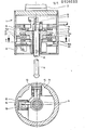
- a multi-coordinate probe 1 has a mandrel 2 for receiving the probe 1 in the spindle of a measuring or processing machine, not shown.
- the probe 1 contains inside the housing 3 a stylus 4 protruding from the housing 3, which can be deflected in all coordinates of a spatial coordinate system.
- the deflection in the Z direction is understood to mean the axial deflection of the stylus 4.
- the stylus 4 is mounted with its shaft in a holder 5 longitudinally displaceable and largely free of play and friction.
- a line grating 7 is arranged as a measuring standard for a digital electrical length measuring device 8 in the extension of the central axis of the stylus 4.
- the multi-coordinate probe works in this Z direction according to the well-known Abbe or comparator principle. Under the action of a spring, not shown, the stylus 4 is always returned to its starting position after the deflections - which corresponds to the zero point position in the Z coordinate axis.
- a ball designed as a precision stop 9 acts as a zero point stop and as an anti-rotation device for the stylus 4.
- the deflection is detected by the digital electrical length measuring devices 10 and 11 visible in FIG.
- the material measures of the length measuring devices 10 and 11 are designed as flat grids 12 and 13. This ensures that the photoelectric sensors 14 and 15 are always in the area of a material measure 12 or 13, i. that is, even if the stylus 4 is deflected in the X direction, the photoelectric sensors 15 for the Y axis do not leave the measuring standard 13 for the Y axis. The same applies to the stylus deflection in the Y direction.
- the stylus 4 is practically just as free of play and friction in the X-Y plane as in the Z direction. This is achieved by a "plane guidance" which allows movement in two degrees of freedom for the stylus 4. A third degree of freedom, the rotation, is prevented in a known manner by an intermediate piece with two link guides 16 arranged in a crossed manner.
- the holder 5 for the stylus 4 extends in a plate-like manner from the center to the outer region of the housing 3.
- On the underside 5a of the plate an extremely flat and exactly perpendicular surface to the stylus axis is created by methods of machining optical surfaces, for example by lapping Ball tread 5a for a precision ball 17 service.
- a disk 18 in the housing 3 forms a support surface 18a for the ball bearing 17.
- This support surface 18a is also machined by lapping.
- the ball bearing 17 runs by spring preload between the ball tread 5a, the bracket 5 and the support surface 18a practically without play. This ensures a play-free and friction-free deflection of the stylus 4 in the plane which is defined by the XY coordinates.
- the stylus 4 can be deflected in any direction in this plane by means of its holder 5; it is prevented from rotating by the cross link 16 hindered.
- the deflection movements are detected by the above-described length measuring devices 10 and 11 and, together with a possible deflection in the Z direction - which is registered by the measuring device 8 - are transmitted via a cable 19 to a known and therefore not shown evaluation device and, if appropriate, in a control device for the Machine processed.
- the person skilled in the art can also provide a wireless transmission device.
Landscapes
- Physics & Mathematics (AREA)
- General Physics & Mathematics (AREA)
- A Measuring Device Byusing Mechanical Method (AREA)
- Length Measuring Devices With Unspecified Measuring Means (AREA)
- Measurement Of Length, Angles, Or The Like Using Electric Or Magnetic Means (AREA)
Applications Claiming Priority (2)
| Application Number | Priority Date | Filing Date | Title |
|---|---|---|---|
| DE3234471 | 1982-09-17 | ||
| DE3234471A DE3234471C1 (de) | 1982-09-17 | 1982-09-17 | Mehrkoordinaten-Tastkopf |
Publications (2)
| Publication Number | Publication Date |
|---|---|
| EP0106033A2 true EP0106033A2 (fr) | 1984-04-25 |
| EP0106033A3 EP0106033A3 (fr) | 1985-09-25 |
Family
ID=6173453
Family Applications (1)
| Application Number | Title | Priority Date | Filing Date |
|---|---|---|---|
| EP83107130A Withdrawn EP0106033A3 (fr) | 1982-09-17 | 1983-07-21 | Tête-palpeur de mesure pour plusieurs coordonnées |
Country Status (4)
| Country | Link |
|---|---|
| US (1) | US4530159A (fr) |
| EP (1) | EP0106033A3 (fr) |
| JP (1) | JPS5973704A (fr) |
| DE (1) | DE3234471C1 (fr) |
Cited By (9)
| Publication number | Priority date | Publication date | Assignee | Title |
|---|---|---|---|---|
| EP0128561A2 (fr) * | 1983-06-09 | 1984-12-19 | Mecof S.p.A. | Palpeur tridimensionnel |
| EP0169416A1 (fr) * | 1984-07-25 | 1986-01-29 | Dr. Johannes Heidenhain GmbH | Tête de palpeur |
| DE3529320A1 (de) * | 1984-08-18 | 1986-02-27 | Mitutoyo Mfg. Co., Ltd., Tokio/Tokyo | Tastvorrichtung fuer oberflaechen |
| EP0583649A1 (fr) * | 1992-08-01 | 1994-02-23 | Hottinger Baldwin Messtechnik Gmbh | Capteur électrique de position |
| DE3546889C2 (de) * | 1984-08-18 | 1994-05-11 | Mitutoyo Mfg Co Ltd | Tastervorrichtung für Oberflächen |
| EP0636859A1 (fr) * | 1993-07-31 | 1995-02-01 | Dr. Johannes Heidenhain GmbH | Tête de mesures tri-dimensionelles |
| DE4308823C2 (de) * | 1993-03-19 | 2002-11-07 | Zeiss Carl | Messender Tastkopf für Koordinatenmeßgeräte |
| FR3021106A1 (fr) * | 2014-05-16 | 2015-11-20 | Cini Sa Atel | Dispositif de controle d'une position d'un trou realise dans une piece. |
| CN110405249A (zh) * | 2019-09-03 | 2019-11-05 | 朗美(厦门)健身器材有限公司 | 自动寻位钻孔机及其自动寻位钻孔方法 |
Families Citing this family (37)
| Publication number | Priority date | Publication date | Assignee | Title |
|---|---|---|---|---|
| JPS60183809U (ja) * | 1984-05-16 | 1985-12-06 | 本田技研工業株式会社 | 位置検出器 |
| JPS617402A (ja) * | 1984-06-21 | 1986-01-14 | Sotsukishiya:Kk | 位置検出装置 |
| JPH0617766B2 (ja) * | 1984-08-23 | 1994-03-09 | 株式会社ミツトヨ | タッチ信号プロ−ブ |
| DE3523188A1 (de) * | 1985-06-28 | 1987-01-08 | Zeiss Carl Fa | Steuerung fuer koordinatenmessgeraete |
| US4752166A (en) * | 1987-01-02 | 1988-06-21 | Manuflex Corp. | Probing device |
| US5154002A (en) * | 1987-02-26 | 1992-10-13 | Klaus Ulbrich | Probe, motion guiding device, position sensing apparatus, and position sensing method |
| US4778313A (en) * | 1987-05-18 | 1988-10-18 | Manuflex Corp. | Intelligent tool system |
| US4882848A (en) * | 1987-07-30 | 1989-11-28 | Carl-Zeiss-Stiftung, Heidenheim/Brenz | Probe head for a coordinate-measuring instrument |
| GB2208934B (en) * | 1987-08-24 | 1991-05-15 | Mitutoyo Corp | Surface contour measuring tracer |
| CH674485A5 (fr) * | 1988-03-11 | 1990-06-15 | Saphirwerk Ind Prod | |
| US5088208A (en) * | 1988-10-11 | 1992-02-18 | Renishaw Plc | Measurement probe for position determining apparatus |
| JPH0789045B2 (ja) * | 1988-12-15 | 1995-09-27 | 富山県 | 三次元変位量測定器 |
| JPH0289311U (fr) * | 1988-12-28 | 1990-07-16 | ||
| US5390424A (en) * | 1990-01-25 | 1995-02-21 | Renishaw Metrology Limited | Analogue probe |
| GB9001682D0 (en) * | 1990-01-25 | 1990-03-28 | Renishaw Plc | Position sensing probe |
| US5491904A (en) * | 1990-02-23 | 1996-02-20 | Mcmurtry; David R. | Touch probe |
| ATE120153T1 (de) * | 1990-10-05 | 1995-04-15 | Ferag Ag | Dickenmessung an druckprodukten in einem schuppenstrom. |
| DE4038698C2 (de) * | 1990-12-05 | 1994-02-10 | Widia Heinlein Gmbh | Meßvorrichtung |
| US5390423A (en) * | 1991-01-22 | 1995-02-21 | Renishaw Plc | Analogue probe |
| GB9111382D0 (en) * | 1991-05-25 | 1991-07-17 | Renishaw Metrology Ltd | Improvements in measuring probes |
| DE4216215A1 (de) * | 1992-05-06 | 1994-01-20 | Max Hobe | Tastfühler |
| JPH07151520A (ja) * | 1993-11-30 | 1995-06-16 | Juki Corp | 厚み検出装置 |
| DE4439578C1 (de) * | 1994-11-05 | 1996-02-08 | Leitz Mestechnik Gmbh | Verfahren zum Auswerten von Sensorsignalen sowie Tastkopf zur Durchführung des Verfahrens |
| JP3474402B2 (ja) * | 1997-07-17 | 2003-12-08 | 株式会社ミツトヨ | 測定器 |
| DE19816827B4 (de) | 1998-04-16 | 2009-06-18 | Dr. Johannes Heidenhain Gmbh | Vormontierte Winkelmeßvorrichtung |
| EP0978708B1 (fr) | 1998-08-01 | 2005-10-05 | Dr. Johannes Heidenhain GmbH | Codeur rotatif |
| US6178653B1 (en) * | 1998-11-20 | 2001-01-30 | Lucent Technologies Inc. | Probe tip locator |
| US6425189B1 (en) * | 1998-11-20 | 2002-07-30 | Agere Systems Guardian Corp. | Probe tip locator having improved marker arrangement for reduced bit encoding error |
| DE19904471B4 (de) | 1999-02-04 | 2011-03-31 | Dr. Johannes Heidenhain Gmbh | Drehgeber |
| DE19907326B4 (de) | 1999-02-20 | 2013-04-04 | Dr. Johannes Heidenhain Gmbh | Winkelmeßsystem |
| GB9907643D0 (en) * | 1999-04-06 | 1999-05-26 | Renishaw Plc | Measuring probe |
| DE19929557B4 (de) | 1999-06-18 | 2006-01-19 | Dr. Johannes Heidenhain Gmbh | Verfahren und Schaltkreis zur Einstellung einer Schaltschwelle eines Tastschalters |
| DE10108774A1 (de) * | 2001-02-23 | 2002-09-05 | Zeiss Carl | Koordinatenmessgerät zum Antasten eines Werkstücks, Tastkopf für ein Koordinatenmessgerät und Verfahren zum Betrieb eines Koordinatenmessgerätes |
| FR2829571A1 (fr) * | 2001-09-11 | 2003-03-14 | Ms Mesure | Systeme et procede de metrologie tridimensionnelle, et micro-machine de mesure mise en oeuvre dans ce systeme |
| GB0228368D0 (en) * | 2002-12-05 | 2003-01-08 | Renishaw Plc | Probe for high speed scanning |
| DE10312789A1 (de) | 2003-03-21 | 2004-10-07 | Stephan Huber | Verfahren und Vorrichtung zum Erfassen einer Länge oder Form eines Werkstücks |
| CN105509606B (zh) * | 2015-12-25 | 2018-03-09 | 辽宁辽旭汽车自动化装备有限公司 | 一种零件开口尺寸及位置度的检测装置 |
Citations (7)
| Publication number | Priority date | Publication date | Assignee | Title |
|---|---|---|---|---|
| DE908350C (de) * | 1951-08-19 | 1954-04-05 | Hanns Fickert | Selbsttaetige Einrichtung zum Abtsten und Nachformen eines Modells |
| CH316493A (de) * | 1953-09-08 | 1956-10-15 | Starrfraesmaschinen Ag | Einrichtung zum Übertragen der Bewegung des Tasterbolzens auf den Steuerschieber bei hydraulischen Steuerungen von Werkzeugmaschinen |
| US2880958A (en) * | 1954-01-15 | 1959-04-07 | United Tool & Die Company | Tracer controlled hydraulic valve |
| US3922791A (en) * | 1974-09-16 | 1975-12-02 | Westinghouse Electric Corp | Profile indicating apparatus displaceable either along an axis or in a plane perpendicular thereto |
| US3957378A (en) * | 1974-11-25 | 1976-05-18 | The Bendix Corporation | Two-axis moire fringe displacement transducer |
| US3991477A (en) * | 1975-07-22 | 1976-11-16 | The Bendix Corporation | Probe for a coordinate measuring machine |
| DE3149278A1 (de) * | 1981-05-30 | 1983-06-23 | Daimler-Benz Ag, 7000 Stuttgart | "kampakte messtasteinrichtung" |
Family Cites Families (14)
| Publication number | Priority date | Publication date | Assignee | Title |
|---|---|---|---|---|
| DE8210960U1 (de) * | 1982-09-16 | A. Rohé GmbH, 6050 Offenbach | Drehuntersatz für Achsmeßgeräte | |
| DE1548326A1 (de) * | 1966-02-04 | 1970-07-02 | Erhard Staedele | Null-Tasteinrichtung fuer Werkzeugmaschinen |
| US3571934A (en) * | 1968-06-24 | 1971-03-23 | Lockheed Aircraft Corp | Three-axis inspection probe |
| US3673695A (en) * | 1970-05-22 | 1972-07-04 | Rohr Corp | Non-tilting probe |
| DE2242355C2 (de) * | 1972-08-29 | 1974-10-17 | Fa. Carl Zeiss, 7920 Heidenheim | Elektronischer Mehrkoordinatentaster |
| DE2535249A1 (de) * | 1975-08-07 | 1977-02-24 | Ver Flugtechnische Werke | Messkopf fuer eine messmaschine |
| GB1597842A (en) * | 1977-02-07 | 1981-09-09 | Rolls Royce | Indexing mechanism |
| DE2712181C3 (de) * | 1977-03-19 | 1981-01-22 | Fa. Carl Zeiss, 7920 Heidenheim | Tastsystem |
| GB1599758A (en) * | 1978-02-10 | 1981-10-07 | Lk Tool Co Ltd | Measuring machine |
| DD141197A1 (de) * | 1978-12-27 | 1980-04-16 | Horst Donat | Koordinatentastkopf zum antasten mehrdimensionaler werkstuecke |
| DE7900134U1 (de) * | 1979-01-04 | 1979-04-26 | Schnabel, Walter, 7141 Schwieberdingen | Dochttraeger |
| JPS5920642Y2 (ja) * | 1979-08-28 | 1984-06-15 | 株式会社 三豊製作所 | タツチ信号プロ−ブ |
| DE2946271A1 (de) * | 1979-11-16 | 1981-05-27 | Vereinigte Flugtechnische Werke Gmbh, 2800 Bremen | Messkopf fuer eine messmaschine |
| JPS58124902A (ja) * | 1982-01-22 | 1983-07-25 | Osaka Kiko Co Ltd | 三軸変位検出器 |
-
1982
- 1982-09-17 DE DE3234471A patent/DE3234471C1/de not_active Expired
-
1983
- 1983-07-21 EP EP83107130A patent/EP0106033A3/fr not_active Withdrawn
- 1983-09-12 US US06/531,422 patent/US4530159A/en not_active Expired - Fee Related
- 1983-09-16 JP JP58169493A patent/JPS5973704A/ja active Pending
Patent Citations (7)
| Publication number | Priority date | Publication date | Assignee | Title |
|---|---|---|---|---|
| DE908350C (de) * | 1951-08-19 | 1954-04-05 | Hanns Fickert | Selbsttaetige Einrichtung zum Abtsten und Nachformen eines Modells |
| CH316493A (de) * | 1953-09-08 | 1956-10-15 | Starrfraesmaschinen Ag | Einrichtung zum Übertragen der Bewegung des Tasterbolzens auf den Steuerschieber bei hydraulischen Steuerungen von Werkzeugmaschinen |
| US2880958A (en) * | 1954-01-15 | 1959-04-07 | United Tool & Die Company | Tracer controlled hydraulic valve |
| US3922791A (en) * | 1974-09-16 | 1975-12-02 | Westinghouse Electric Corp | Profile indicating apparatus displaceable either along an axis or in a plane perpendicular thereto |
| US3957378A (en) * | 1974-11-25 | 1976-05-18 | The Bendix Corporation | Two-axis moire fringe displacement transducer |
| US3991477A (en) * | 1975-07-22 | 1976-11-16 | The Bendix Corporation | Probe for a coordinate measuring machine |
| DE3149278A1 (de) * | 1981-05-30 | 1983-06-23 | Daimler-Benz Ag, 7000 Stuttgart | "kampakte messtasteinrichtung" |
Cited By (10)
| Publication number | Priority date | Publication date | Assignee | Title |
|---|---|---|---|---|
| EP0128561A2 (fr) * | 1983-06-09 | 1984-12-19 | Mecof S.p.A. | Palpeur tridimensionnel |
| EP0128561A3 (fr) * | 1983-06-09 | 1986-03-19 | Mecof S.p.A. | Palpeur tridimensionnel |
| EP0169416A1 (fr) * | 1984-07-25 | 1986-01-29 | Dr. Johannes Heidenhain GmbH | Tête de palpeur |
| DE3529320A1 (de) * | 1984-08-18 | 1986-02-27 | Mitutoyo Mfg. Co., Ltd., Tokio/Tokyo | Tastvorrichtung fuer oberflaechen |
| DE3546889C2 (de) * | 1984-08-18 | 1994-05-11 | Mitutoyo Mfg Co Ltd | Tastervorrichtung für Oberflächen |
| EP0583649A1 (fr) * | 1992-08-01 | 1994-02-23 | Hottinger Baldwin Messtechnik Gmbh | Capteur électrique de position |
| DE4308823C2 (de) * | 1993-03-19 | 2002-11-07 | Zeiss Carl | Messender Tastkopf für Koordinatenmeßgeräte |
| EP0636859A1 (fr) * | 1993-07-31 | 1995-02-01 | Dr. Johannes Heidenhain GmbH | Tête de mesures tri-dimensionelles |
| FR3021106A1 (fr) * | 2014-05-16 | 2015-11-20 | Cini Sa Atel | Dispositif de controle d'une position d'un trou realise dans une piece. |
| CN110405249A (zh) * | 2019-09-03 | 2019-11-05 | 朗美(厦门)健身器材有限公司 | 自动寻位钻孔机及其自动寻位钻孔方法 |
Also Published As
| Publication number | Publication date |
|---|---|
| DE3234471C1 (de) | 1983-08-25 |
| JPS5973704A (ja) | 1984-04-26 |
| US4530159A (en) | 1985-07-23 |
| EP0106033A3 (fr) | 1985-09-25 |
Similar Documents
| Publication | Publication Date | Title |
|---|---|---|
| DE3234471C1 (de) | Mehrkoordinaten-Tastkopf | |
| DE2620099C2 (de) | Tastkopf mit allseitig auslenkbarem Taster | |
| DE3629689A1 (de) | Positions-messvorrichtung | |
| EP1721118B1 (fr) | Tete de palpage pour un appareil de mesure de coordonnees | |
| DE3234470A1 (de) | Mehrkoordinaten-tastkopf | |
| CH674485A5 (fr) | ||
| DE19508861A1 (de) | Koordinatenmeßgerät mit einer Einrichtung für die Rauheitsmessung | |
| DE3229992A1 (de) | Mehrkoordinaten-tastkopf | |
| DE3719731C2 (fr) | ||
| DE2718506C2 (de) | Mehrkoordinaten-Meßmaschine | |
| DE2741413A1 (de) | Zweiachsige fuehlervorrichtung zur steuerung von einrichtungen zum kopieren von schablonen fuer werkzeugmaschinen | |
| DE3724137C2 (de) | Elektronisches Meßgerät mit Digitalanzeige | |
| EP2795243B1 (fr) | Appareil de mesure de coordonnées avec un ensemble d'interfaces amélioré | |
| DE19913659B4 (de) | Positionserfassungsgerät | |
| DE8226204U1 (de) | Mehrkoordinaten-Tastkopf | |
| EP0628785A2 (fr) | Tête de palpage de plusieurs coordonnées | |
| DE3509502A1 (de) | Positionsfuehleinrichtung | |
| DE2935898C2 (de) | Rotationstransduktor zur Positionsmessung | |
| EP0103090B1 (fr) | Palpeur de mesure avec protection contre les surcharges | |
| DE2400952C3 (de) | Fühlhebelmeßgerät | |
| DE3609283C1 (en) | Probe (tracer) | |
| DE644928C (de) | Vorrichtung zum Nachpruefen fein bearbeiteter konischer Bohrungen | |
| EP3236194B1 (fr) | Machine a mesurer tridimensionnelle comprenant une tete de palpage analogique et procede de mesure d'une piece a l'aide d'une machine a mesurer tridimensionnelle | |
| DE2252465A1 (de) | Induktiv arbeitender messfuehler | |
| DD287993A5 (de) | Dreidimensionaler taktiler geber mit magnetischer umsetzung und rueckstellung |
Legal Events
| Date | Code | Title | Description |
|---|---|---|---|
| PUAI | Public reference made under article 153(3) epc to a published international application that has entered the european phase |
Free format text: ORIGINAL CODE: 0009012 |
|
| 17P | Request for examination filed |
Effective date: 19830729 |
|
| AK | Designated contracting states |
Designated state(s): AT CH FR GB IT LI NL SE |
|
| PUAL | Search report despatched |
Free format text: ORIGINAL CODE: 0009013 |
|
| STAA | Information on the status of an ep patent application or granted ep patent |
Free format text: STATUS: THE APPLICATION HAS BEEN WITHDRAWN |
|
| AK | Designated contracting states |
Designated state(s): AT CH FR GB IT LI NL SE |
|
| 18W | Application withdrawn |
Withdrawal date: 19850731 |
|
| RIN1 | Information on inventor provided before grant (corrected) |
Inventor name: ERNST, ALFONS, DIPL.-ING. |