EP0106033A2 - Feeler head for two or more coordinates measurement - Google Patents
Feeler head for two or more coordinates measurement Download PDFInfo
- Publication number
- EP0106033A2 EP0106033A2 EP83107130A EP83107130A EP0106033A2 EP 0106033 A2 EP0106033 A2 EP 0106033A2 EP 83107130 A EP83107130 A EP 83107130A EP 83107130 A EP83107130 A EP 83107130A EP 0106033 A2 EP0106033 A2 EP 0106033A2
- Authority
- EP
- European Patent Office
- Prior art keywords
- coordinate
- stylus
- probe according
- guide
- coordinate probe
- Prior art date
- Legal status (The legal status is an assumption and is not a legal conclusion. Google has not performed a legal analysis and makes no representation as to the accuracy of the status listed.)
- Withdrawn
Links
- 238000005259 measurement Methods 0.000 title 1
- 241001422033 Thestylus Species 0.000 claims abstract description 25
- 239000000523 sample Substances 0.000 claims abstract description 24
- 239000000463 material Substances 0.000 claims abstract description 4
- 238000003754 machining Methods 0.000 claims description 2
- 238000000034 method Methods 0.000 claims description 2
- 230000003287 optical effect Effects 0.000 claims description 2
- 230000000694 effects Effects 0.000 description 2
- 230000005540 biological transmission Effects 0.000 description 1
- 238000011156 evaluation Methods 0.000 description 1
- 238000004519 manufacturing process Methods 0.000 description 1
- 230000036316 preload Effects 0.000 description 1
- 238000003860 storage Methods 0.000 description 1
- 238000011144 upstream manufacturing Methods 0.000 description 1
Images
Classifications
-
- G—PHYSICS
- G01—MEASURING; TESTING
- G01B—MEASURING LENGTH, THICKNESS OR SIMILAR LINEAR DIMENSIONS; MEASURING ANGLES; MEASURING AREAS; MEASURING IRREGULARITIES OF SURFACES OR CONTOURS
- G01B11/00—Measuring arrangements characterised by the use of optical techniques
- G01B11/002—Measuring arrangements characterised by the use of optical techniques for measuring two or more coordinates
- G01B11/005—Measuring arrangements characterised by the use of optical techniques for measuring two or more coordinates coordinate measuring machines
- G01B11/007—Measuring arrangements characterised by the use of optical techniques for measuring two or more coordinates coordinate measuring machines feeler heads therefor
-
- G—PHYSICS
- G01—MEASURING; TESTING
- G01B—MEASURING LENGTH, THICKNESS OR SIMILAR LINEAR DIMENSIONS; MEASURING ANGLES; MEASURING AREAS; MEASURING IRREGULARITIES OF SURFACES OR CONTOURS
- G01B5/00—Measuring arrangements characterised by the use of mechanical techniques
- G01B5/004—Measuring arrangements characterised by the use of mechanical techniques for measuring coordinates of points
- G01B5/008—Measuring arrangements characterised by the use of mechanical techniques for measuring coordinates of points using coordinate measuring machines
- G01B5/012—Contact-making feeler heads therefor
-
- G—PHYSICS
- G01—MEASURING; TESTING
- G01B—MEASURING LENGTH, THICKNESS OR SIMILAR LINEAR DIMENSIONS; MEASURING ANGLES; MEASURING AREAS; MEASURING IRREGULARITIES OF SURFACES OR CONTOURS
- G01B7/00—Measuring arrangements characterised by the use of electric or magnetic techniques
- G01B7/004—Measuring arrangements characterised by the use of electric or magnetic techniques for measuring coordinates of points
- G01B7/008—Measuring arrangements characterised by the use of electric or magnetic techniques for measuring coordinates of points using coordinate measuring machines
- G01B7/012—Contact-making feeler heads therefor
Definitions
- the invention relates to a multi-coordinate probe according to the preamble of claim 1.
- Multi-coordinate probes for probing workpieces in several directions are known.
- the probes can be divided into two categories 1.
- the styli make an angular movement when they are deflected normally to their axis.
- the stylus is movably supported over straight guides.
- DE-PS 22 42 355 an electronic multi-coordinate scanner is described, which is characterized by a combination of individual features.
- a torsionally stiff sequence of backlash-free and friction-free linear guidance systems forms a defined flat or spatial coordinate system. This series of straight-line guidance systems improves the state of the art, as is set out in detail in the introduction to the document.
- the one straight guide system is based on the accuracy of the upstream straight guide system.
- the individual straight guide systems have to be manufactured with enormous accuracy. This requires a very high level of design and manufacturing effort.
- it is a peculiarity of linear guidance systems designed as spring parallelograms that the distance of the plates moving parallel to one another changes in the event of deflections. This effect is certainly only negligibly small with very small deflections.
- the invention has for its object to provide a multi-coordinate probe, which does not have the known disadvantages of the probes according to the prior art, which is nevertheless relatively simple, which is versatile and robust.
- the particular advantages of the probe according to the invention are that the stylus is guided in two planes in one plane, so that there is no interdependency on the The respective accuracy of two individual straight-line guidance systems is lined up and that the same degrees of freedom are nevertheless present. To a certain extent, the straight guidance systems are not lined up, but placed on one level. Another advantageous effect is the reduction of the overall height through this measure.
- a multi-coordinate probe 1 has a mandrel 2 for receiving the probe 1 in the spindle of a measuring or processing machine, not shown.
- the probe 1 contains inside the housing 3 a stylus 4 protruding from the housing 3, which can be deflected in all coordinates of a spatial coordinate system.
- the deflection in the Z direction is understood to mean the axial deflection of the stylus 4.
- the stylus 4 is mounted with its shaft in a holder 5 longitudinally displaceable and largely free of play and friction.
- a line grating 7 is arranged as a measuring standard for a digital electrical length measuring device 8 in the extension of the central axis of the stylus 4.
- the multi-coordinate probe works in this Z direction according to the well-known Abbe or comparator principle. Under the action of a spring, not shown, the stylus 4 is always returned to its starting position after the deflections - which corresponds to the zero point position in the Z coordinate axis.
- a ball designed as a precision stop 9 acts as a zero point stop and as an anti-rotation device for the stylus 4.
- the deflection is detected by the digital electrical length measuring devices 10 and 11 visible in FIG.
- the material measures of the length measuring devices 10 and 11 are designed as flat grids 12 and 13. This ensures that the photoelectric sensors 14 and 15 are always in the area of a material measure 12 or 13, i. that is, even if the stylus 4 is deflected in the X direction, the photoelectric sensors 15 for the Y axis do not leave the measuring standard 13 for the Y axis. The same applies to the stylus deflection in the Y direction.
- the stylus 4 is practically just as free of play and friction in the X-Y plane as in the Z direction. This is achieved by a "plane guidance" which allows movement in two degrees of freedom for the stylus 4. A third degree of freedom, the rotation, is prevented in a known manner by an intermediate piece with two link guides 16 arranged in a crossed manner.
- the holder 5 for the stylus 4 extends in a plate-like manner from the center to the outer region of the housing 3.
- On the underside 5a of the plate an extremely flat and exactly perpendicular surface to the stylus axis is created by methods of machining optical surfaces, for example by lapping Ball tread 5a for a precision ball 17 service.
- a disk 18 in the housing 3 forms a support surface 18a for the ball bearing 17.
- This support surface 18a is also machined by lapping.
- the ball bearing 17 runs by spring preload between the ball tread 5a, the bracket 5 and the support surface 18a practically without play. This ensures a play-free and friction-free deflection of the stylus 4 in the plane which is defined by the XY coordinates.
- the stylus 4 can be deflected in any direction in this plane by means of its holder 5; it is prevented from rotating by the cross link 16 hindered.
- the deflection movements are detected by the above-described length measuring devices 10 and 11 and, together with a possible deflection in the Z direction - which is registered by the measuring device 8 - are transmitted via a cable 19 to a known and therefore not shown evaluation device and, if appropriate, in a control device for the Machine processed.
- the person skilled in the art can also provide a wireless transmission device.
Landscapes
- Physics & Mathematics (AREA)
- General Physics & Mathematics (AREA)
- A Measuring Device Byusing Mechanical Method (AREA)
- Measurement Of Length, Angles, Or The Like Using Electric Or Magnetic Means (AREA)
- Length Measuring Devices With Unspecified Measuring Means (AREA)
Abstract
Bei diesem Mehrkoordinatentaster (1) wird die Auslenkung des Taststiftes (4) bei Werkstückantastung in beliebiger Richtung durch präzise Führungen (6, 5a, 18a) ermöglicht. Die Führung für die Taststiftauslenkung in Z-Richtung wird dabei von einer Kugelgeradführung (6) übernommen, die Führung in der X-Y-Ebene erfolgt durch eine ebene Führung (5a, 18a) in zwei Freiheitsgraden. Die Verdrehsicherung wird durch einen Präzisionsanschlag (9) bzw. durch Kulissenführungen (16) gewährleistet. Die Größe der Auslenkung wird von lichtelektrischen Längenmeßeinrichtungen (8, 10, 11) ermittelt, von denen die Meßeinrichtungen (10, 11) für die X-Y-Ebene flächige Gitter als Maßverkörperungen (12, 13) aufweisen.With this multi-coordinate probe (1), the deflection of the stylus (4) is made possible by precise guides (6, 5a, 18a) when probing the workpiece in any direction. The guide for the stylus deflection in the Z direction is taken over by a ball straight guide (6), the guide in the X-Y plane is carried out by a flat guide (5a, 18a) in two degrees of freedom. The anti-rotation device is guaranteed by a precision stop (9) or by slide guides (16). The size of the deflection is determined by photoelectric length measuring devices (8, 10, 11), of which the measuring devices (10, 11) have flat grids for the X-Y plane as material measures (12, 13).
Description
Die Erfindung bezieht sich auf einen Mehrkoordinaten-Tastkopf nach dem Oberbegriff des Anspruches 1.The invention relates to a multi-coordinate probe according to the preamble of claim 1.
Es sind Mehrkoordinaten-Tastköpfe zum Antasten von Werkstücken in mehreren Richtungen bekannt. Dabei können die Tastköpfe in zwei Kategorien 1 eingeteilt werden. In der einen Kategorie machen die Taststifte eine Winkelbewegung wenn sie normal zu ihrer Achse ausgelenkt werden. Bei der anderen Kategorie ist der Taststift über Geradführungen beweglich gelagert. In der DE-PS 22 42 355 ist ein elektronischer Mehrkoordinatentaster beschrieben, der durch eine Kombination von Einzelmerkmalen gekennzeichnet ist. Eine torsionssteife Aneinanderreihung von spiel- und reibungsfreien Geradführungssystemen bildet ein definiertes ebenes oder räumliches Koordinatensystem. Diese Aneinanderreihung von Geradführungssystemen verbessert den Stand der Technik wie ausführlich in der Beschreibungseinleitung der genannten Schrift dargelegt ist. Jedoch weist die dort vorgeschlagene Lösung noch Mängel auf, da bei einer dem dortigen Ausführungsbeispiel entsprechenden Aneinanderreihung von Federparallelogrammen das eine GeradL führungssystem auf der Genauigkeit des vorgelagerten Geradführungssystemes aufbaut. Um bei einer derartigen Aneinanderreihung von Geradführungen - wie sie auch ein Kreuztisch darstellt - eine den Erfordernissen entsprechende Genauigkeit zu erzielen, müssen die einzelnen Geradführungssysteme mit einer enormen Genauigkeit hergestellt werden. Dies erfordert einen sehr hohen konstruktiven und fertigungstechnischen Aufwand. Zudem ist es eine Eigenheit von als Federparallelogrammen ausgeführten Geradführungssystemen, daß sich bei Auslenkungen der Abstand der parallel zueinander bewegten Platten verändert. Dieser Effekt ist sicher nur bei sehr kleinen Auslenkungen vernachlässigbar klein.Multi-coordinate probes for probing workpieces in several directions are known. The probes can be divided into two categories 1. In one category, the styli make an angular movement when they are deflected normally to their axis. In the other category, the stylus is movably supported over straight guides. In DE-PS 22 42 355 an electronic multi-coordinate scanner is described, which is characterized by a combination of individual features. A torsionally stiff sequence of backlash-free and friction-free linear guidance systems forms a defined flat or spatial coordinate system. This series of straight-line guidance systems improves the state of the art, as is set out in detail in the introduction to the document. However, the one suggested there Solution still shortcomings, since in a sequence of spring parallelograms corresponding to the exemplary embodiment there, the one straight guide system is based on the accuracy of the upstream straight guide system. In order to achieve an accuracy corresponding to the requirements with such a series of straight guides - as also represented by a cross table - the individual straight guide systems have to be manufactured with enormous accuracy. This requires a very high level of design and manufacturing effort. In addition, it is a peculiarity of linear guidance systems designed as spring parallelograms that the distance of the plates moving parallel to one another changes in the event of deflections. This effect is certainly only negligibly small with very small deflections.
1 Der Erfindung liegt die Aufgabe zugrunde, einen Mehrkoordinaten-Tastkopf zu schaffen, der nicht die bekannten Nachteile der Tastköpfe gemäß dem Stand der Technik aufweist, der dennoch verhältnismäßig einfach aufgebaut ist, der vielseitig einsetzbar und robust ist.1 The invention has for its object to provide a multi-coordinate probe, which does not have the known disadvantages of the probes according to the prior art, which is nevertheless relatively simple, which is versatile and robust.
Diese Aufgabe wird durch einen Tastkopf gelöst, der durch die kennzeichnenden Merkmale des Anspruches 1 gekennzeichnet ist.This object is achieved by a probe, which is characterized by the characterizing features of claim 1.
Die besonderen Vorteile des erfindungsgemäßen Tastkopfes liegen darin, daß der Taststift in einer Ebene in zwei Freiheitsgrade geführt ist, daß also keine gegenseitige Abhängigkeit von der jeweiligen Genauigkeit zweier einzelner aneinandergereihter Geradführungssysteme besteht und daß dennoch die gleichen Freiheitsgrade vorhanden sind. Die Geradführungssysteme werden gewissermaßen nicht aneinandergereiht, sondern in eine Ebene gelegt. Ein weiterer vorteilhafter Effekt ist die Verringerung der Bauhöhe durch diese Maßnahme.The particular advantages of the probe according to the invention are that the stylus is guided in two planes in one plane, so that there is no interdependency on the The respective accuracy of two individual straight-line guidance systems is lined up and that the same degrees of freedom are nevertheless present. To a certain extent, the straight guidance systems are not lined up, but placed on one level. Another advantageous effect is the reduction of the overall height through this measure.
Weitere vorteilhafte Ausgestaltungen der Erfindung ergeben sich aus den Unteransprüchen.Further advantageous embodiments of the invention result from the subclaims.
Mit Hilfe der Zeichnungen soll anhand eines Ausführungsbeispiels die Erfindung noch näher erläutert werden.With the help of the drawings, the invention will be explained in more detail using an exemplary embodiment.
Es zeigen
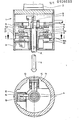
- Figur 1 den Schnitt durch einen schematisch dargestellten Tastkopf,
Figur 2 eine Schnittdarstellung entlang der Linie I-I in Figur 1.
- FIG. 1 shows the section through a schematically represented probe head,
- FIG. 2 shows a sectional illustration along the line II in FIG. 1.
Ein Mehrkoordinaten-Tastkopf 1 weist einen Aufnahmedorn 2 zur Aufnahme des Tastkopfes 1 in der Spindel einer nicht dargestellten Meß- oder Bearbeitungsmaschine auf. Der Tastkopf 1 enthält im Innern seines Gehäuses 3 einen aus dem Gehäuse 3 herausragenden Taststift 4, der in allen Koordinaten eines räumlichen Koordinatensystems auslenkbar ist. Als Auslenkung in der Z-Richtung wird dabei die axiale Auslenkung des Taststiftes 4 verstanden. Der Taststift 4 ist mit seinem Schaft in einer Halterung 5 längsverschieblich und weitestgehend spiel- und reibungsfrei gelagert.A multi-coordinate probe 1 has a
Die praktisch spiel- und reibungsfreie Lagerung wird durch eine Präzisionskugelführung 6 ermöglicht. Am im Gehäuse 3 befindlichen Endes des ' Taststiftes 4 ist in Verlängerung der Mittelachse des Taststiftes 4 ein Strichgitter 7 als Maßverkörperung für eine digitale elektrische Längenmaßeinrichtung 8 angeordnet. In dieser Z-Richtung arbeitet der Mehrkoordinaten-Tastkopf also nach dem bekannten Abbe- oder Komparatorprinzip. Unter der Wirkung einer nicht dargestellten Feder wird der Taststift 4 nach Auslenkungen immer wieder in seine Ausgangslage - die der Nullpunktlage in der Z-Koordinatenachse entspricht - zurückgestellt. Eine als Präzisionsanschlag 9 ausgebildete Kugel wirkt dabei als Nullpunktanschlag und als Verdrehsicherung des Taststiftes 4.The practically backlash-free and friction-free storage is made possible by a
Bei der Auslenkung des Taststiftes 4 in einer zur Z-Richtung senkrechten Ebene, die durch das X-Y Koordinatensystem bestimmt ist, wird die Auslenkung von den in Figur 2 sichtbaren digitalen elektrischen Längenmeßeinrichtungen 10 und 11 erfaßt. Die Maßverkörperungen der Längenmeßeinrichtungen 10 und 11 sind als flächige Gitter 12 und 13 ausgebildet. Dadurch wird sichergestellt, daß die photoelektrischen Sensoren 14 und 15 sich immer im Bereich einer Maßverkörperung 12 oder 13 befinden, d. h., auch wenn der Taststift 4 in X-Richtung ausgelenkt wird, verlassen die photoelektrischen Sensoren 15 für die Y-Achse nicht die Maßverkörperung 13 für die Y-Achse. Entsprechendes gilt für die Taststiftauslenkung in Y-Richtung.When the stylus 4 is deflected in a plane perpendicular to the Z direction, which is determined by the X-Y coordinate system, the deflection is detected by the digital electrical
Bei Auslenkungen des Taststiftes 4, die nicht genau in den rechtwinklig zueinander stehenden Koordinatenachsen erfolgen, werden die Richtungskomponenten von den Sensoren 14 und 15 ermittelt, so daß die Auslenkungskoordinaten bestimmt sind.With deflections of the stylus 4, which are not ge the directional components are determined by the
Der Taststift 4 wird bei Auslenkungen in der X-Y-Ebene praktisch ebenso spiel- und reibungsfrei geführt, wie in der Z-Richtung. Dies wird durch eine "Ebenenführung" erreicht, die für den Taststift 4 eine Bewegung in zwei Freiheitsgraden zuläßt. Ein dritter Freiheitsgrad, die Drehung, wird in bekannter Weise durch ein Zwischenstück mit zwei gekreuzt angeordneten Kulissenführungen 16 verhindert.The stylus 4 is practically just as free of play and friction in the X-Y plane as in the Z direction. This is achieved by a "plane guidance" which allows movement in two degrees of freedom for the stylus 4. A third degree of freedom, the rotation, is prevented in a known manner by an intermediate piece with two
Die Halterung 5 für den Taststift 4 erstreckt sich tellerartig vom Zentrum zum Außenbereich des Gehäuses 3. Auf der Unterseite 5a des Tellers ist durch Methoden der Bearbeitung optischer Flächen, beispielsweise durch Läppen,-eine äußerst ebene und genau zur Taststiftachse senkrechte Fläche geschaffen, die als Kugellauffläche 5a für ein Präzisionskugeln 17 dienst. Eine Scheibe 18 im Gehäuse 3 bildet eine Stützfläche 18a für das Kugellager 17. Diese Stützfläche 18a ist ebenfalls durch Läppen bearbeitet. Das Kugellager 17 läuft durch Federvorspannung zwischen der Kugellauffläche 5a, der Halterung 5 und der Stützfläche 18a praktisch spielfrei. Damit ist eine spiel- und reibungsfreie Auslenkung des Taststiftes 4 in der Ebene, die durch die X-Y-Koordinaten definiert wird, gewährleistet. Der Taststift 4 ist mittels seiner Halterung 5 in beliebiger Richtung in dieser Ebene auslenkbar, gegen Verdrehung ist er durch die Kreuzkulisse 16 gehindert. Die Auslenkbewegungen werden von den vorbeschriebenen Längenmeßeinrichtungen 10 und 11 erfaßt und zusammen mit einer eventuellen Auslenkung in Z-Richtung - die von der Meßeinrichtung 8 registriert wird - über ein Kabel 19 in eine bekannte und daher nicht dargestellten Auswerteeinrichtung übertragen und gegebenenfalls in einer Steuereinrichtung für die Maschine verarbeitet.The
Anstelle des Kabelausganges 19 für die Auslenksignale kann der Fachmann auch eine drahtlose Übertragungseinrichtung vorsehen.Instead of the
Die präzise Rückstellung der Auslenkung in der X-Y-Ebene kann durch angefderte Kugeln 20 erfolgen, die sich in kegeligen Gegenlagern 21 auf der Unterseite 18b der Scheibe 18 selbst zentrieren. Dadurch wird der Taststift 4 mit seiner Halterung 5 immer exakt in die Nullpunktlage des X-Y-Koordinatensystems zurückgestellt. Selbstverständlich kann auch eine andere, dem Fachmann geläufige Rückstelleinrichtung vorgesehen sein.The precise resetting of the deflection in the X-Y plane can be achieved by spring-loaded
Claims (10)
Applications Claiming Priority (2)
| Application Number | Priority Date | Filing Date | Title |
|---|---|---|---|
| DE3234471 | 1982-09-17 | ||
| DE3234471A DE3234471C1 (en) | 1982-09-17 | 1982-09-17 | Multi-coordinate probe |
Publications (2)
| Publication Number | Publication Date |
|---|---|
| EP0106033A2 true EP0106033A2 (en) | 1984-04-25 |
| EP0106033A3 EP0106033A3 (en) | 1985-09-25 |
Family
ID=6173453
Family Applications (1)
| Application Number | Title | Priority Date | Filing Date |
|---|---|---|---|
| EP83107130A Withdrawn EP0106033A3 (en) | 1982-09-17 | 1983-07-21 | Feeler head for two or more coordinates measurement |
Country Status (4)
| Country | Link |
|---|---|
| US (1) | US4530159A (en) |
| EP (1) | EP0106033A3 (en) |
| JP (1) | JPS5973704A (en) |
| DE (1) | DE3234471C1 (en) |
Cited By (9)
| Publication number | Priority date | Publication date | Assignee | Title |
|---|---|---|---|---|
| EP0128561A2 (en) * | 1983-06-09 | 1984-12-19 | Mecof S.p.A. | Three-dimensional feeler head |
| EP0169416A1 (en) * | 1984-07-25 | 1986-01-29 | Dr. Johannes Heidenhain GmbH | Position-sensing probe |
| DE3529320A1 (en) * | 1984-08-18 | 1986-02-27 | Mitutoyo Mfg. Co., Ltd., Tokio/Tokyo | PROBE DEVICE FOR SURFACES |
| EP0583649A1 (en) * | 1992-08-01 | 1994-02-23 | Hottinger Baldwin Messtechnik Gmbh | Electrical position sensor |
| DE3546889C2 (en) * | 1984-08-18 | 1994-05-11 | Mitutoyo Mfg Co Ltd | Surface tracer detecting three-dimensional coordinates of workpiece |
| EP0636859A1 (en) * | 1993-07-31 | 1995-02-01 | Dr. Johannes Heidenhain GmbH | Three-coördinate measuring head |
| DE4308823C2 (en) * | 1993-03-19 | 2002-11-07 | Zeiss Carl | Measuring probe for coordinate measuring machines |
| FR3021106A1 (en) * | 2014-05-16 | 2015-11-20 | Cini Sa Atel | DEVICE FOR CONTROLLING A POSITION OF A HOLE MADE IN A WORKPIECE. |
| CN110405249A (en) * | 2019-09-03 | 2019-11-05 | 朗美(厦门)健身器材有限公司 | Automatic localization drilling machine and its automatic localization boring method |
Families Citing this family (37)
| Publication number | Priority date | Publication date | Assignee | Title |
|---|---|---|---|---|
| JPS60183809U (en) * | 1984-05-16 | 1985-12-06 | 本田技研工業株式会社 | position detector |
| JPS617402A (en) * | 1984-06-21 | 1986-01-14 | Sotsukishiya:Kk | Position detector |
| JPH0617766B2 (en) * | 1984-08-23 | 1994-03-09 | 株式会社ミツトヨ | Touch signal probe |
| DE3523188A1 (en) * | 1985-06-28 | 1987-01-08 | Zeiss Carl Fa | CONTROL FOR COORDINATE MEASURING DEVICES |
| US4752166A (en) * | 1987-01-02 | 1988-06-21 | Manuflex Corp. | Probing device |
| US5154002A (en) * | 1987-02-26 | 1992-10-13 | Klaus Ulbrich | Probe, motion guiding device, position sensing apparatus, and position sensing method |
| US4778313A (en) * | 1987-05-18 | 1988-10-18 | Manuflex Corp. | Intelligent tool system |
| US4882848A (en) * | 1987-07-30 | 1989-11-28 | Carl-Zeiss-Stiftung, Heidenheim/Brenz | Probe head for a coordinate-measuring instrument |
| GB2208934B (en) * | 1987-08-24 | 1991-05-15 | Mitutoyo Corp | Surface contour measuring tracer |
| CH674485A5 (en) * | 1988-03-11 | 1990-06-15 | Saphirwerk Ind Prod | |
| EP0407489B1 (en) * | 1988-10-11 | 1994-03-23 | Renishaw plc | Measurement probe using bearings with centralised rolling elements |
| JPH0789045B2 (en) * | 1988-12-15 | 1995-09-27 | 富山県 | Three-dimensional displacement measuring instrument |
| JPH0289311U (en) * | 1988-12-28 | 1990-07-16 | ||
| GB9001682D0 (en) * | 1990-01-25 | 1990-03-28 | Renishaw Plc | Position sensing probe |
| US5390424A (en) * | 1990-01-25 | 1995-02-21 | Renishaw Metrology Limited | Analogue probe |
| US5491904A (en) * | 1990-02-23 | 1996-02-20 | Mcmurtry; David R. | Touch probe |
| EP0479717B1 (en) * | 1990-10-05 | 1995-03-22 | Ferag AG | Device for measuring the thickness of printed products in a shingled formation |
| DE4038698C2 (en) * | 1990-12-05 | 1994-02-10 | Widia Heinlein Gmbh | Measuring device |
| US5390423A (en) * | 1991-01-22 | 1995-02-21 | Renishaw Plc | Analogue probe |
| GB9111382D0 (en) * | 1991-05-25 | 1991-07-17 | Renishaw Metrology Ltd | Improvements in measuring probes |
| DE4216215A1 (en) * | 1992-05-06 | 1994-01-20 | Max Hobe | Sensor probe for workpiece measuring device |
| JPH07151520A (en) * | 1993-11-30 | 1995-06-16 | Juki Corp | Thickness detecting device |
| DE4439578C1 (en) * | 1994-11-05 | 1996-02-08 | Leitz Mestechnik Gmbh | Coordinate measuring machine sensor head |
| JP3474402B2 (en) * | 1997-07-17 | 2003-12-08 | 株式会社ミツトヨ | Measuring instrument |
| DE19816827B4 (en) | 1998-04-16 | 2009-06-18 | Dr. Johannes Heidenhain Gmbh | Pre-assembled angle measuring device |
| DE59912617D1 (en) | 1998-08-01 | 2006-02-16 | Heidenhain Gmbh Dr Johannes | Rotary position measuring device |
| US6178653B1 (en) * | 1998-11-20 | 2001-01-30 | Lucent Technologies Inc. | Probe tip locator |
| US6425189B1 (en) * | 1998-11-20 | 2002-07-30 | Agere Systems Guardian Corp. | Probe tip locator having improved marker arrangement for reduced bit encoding error |
| DE19904471B4 (en) | 1999-02-04 | 2011-03-31 | Dr. Johannes Heidenhain Gmbh | encoders |
| DE19907326B4 (en) | 1999-02-20 | 2013-04-04 | Dr. Johannes Heidenhain Gmbh | angle measurement |
| GB9907643D0 (en) * | 1999-04-06 | 1999-05-26 | Renishaw Plc | Measuring probe |
| DE19929557B4 (en) | 1999-06-18 | 2006-01-19 | Dr. Johannes Heidenhain Gmbh | Method and circuit for setting a switching threshold of a key switch |
| DE10108774A1 (en) * | 2001-02-23 | 2002-09-05 | Zeiss Carl | Coordinate measuring device for probing a workpiece, probe for a coordinate measuring device and method for operating a coordinate measuring device |
| FR2829571A1 (en) * | 2001-09-11 | 2003-03-14 | Ms Mesure | Three dimensional digital metrology measurement of objects using a micro-machine, uses contact and/or laser non contact at end of rod linked to three dimensional positioning system |
| GB0228368D0 (en) * | 2002-12-05 | 2003-01-08 | Renishaw Plc | Probe for high speed scanning |
| DE10312789A1 (en) | 2003-03-21 | 2004-10-07 | Stephan Huber | Method and device for detecting a length or shape of a workpiece |
| CN105509606B (en) * | 2015-12-25 | 2018-03-09 | 辽宁辽旭汽车自动化装备有限公司 | A kind of detection means of part opening size and position degree |
Citations (7)
| Publication number | Priority date | Publication date | Assignee | Title |
|---|---|---|---|---|
| DE908350C (en) * | 1951-08-19 | 1954-04-05 | Hanns Fickert | Automatic device for sampling and reshaping a model |
| CH316493A (en) * | 1953-09-08 | 1956-10-15 | Starrfraesmaschinen Ag | Device for transferring the movement of the probe pin to the control slide in hydraulic controls of machine tools |
| US2880958A (en) * | 1954-01-15 | 1959-04-07 | United Tool & Die Company | Tracer controlled hydraulic valve |
| US3922791A (en) * | 1974-09-16 | 1975-12-02 | Westinghouse Electric Corp | Profile indicating apparatus displaceable either along an axis or in a plane perpendicular thereto |
| US3957378A (en) * | 1974-11-25 | 1976-05-18 | The Bendix Corporation | Two-axis moire fringe displacement transducer |
| US3991477A (en) * | 1975-07-22 | 1976-11-16 | The Bendix Corporation | Probe for a coordinate measuring machine |
| DE3149278A1 (en) * | 1981-05-30 | 1983-06-23 | Daimler-Benz Ag, 7000 Stuttgart | Compact measuring plunger device |
Family Cites Families (14)
| Publication number | Priority date | Publication date | Assignee | Title |
|---|---|---|---|---|
| DE8210960U1 (en) * | 1982-09-16 | A. Rohé GmbH, 6050 Offenbach | Rotary base for wheel aligners | |
| DE1548326A1 (en) * | 1966-02-04 | 1970-07-02 | Erhard Staedele | Zero touch device for machine tools |
| US3571934A (en) * | 1968-06-24 | 1971-03-23 | Lockheed Aircraft Corp | Three-axis inspection probe |
| US3673695A (en) * | 1970-05-22 | 1972-07-04 | Rohr Corp | Non-tilting probe |
| DE2242355C2 (en) * | 1972-08-29 | 1974-10-17 | Fa. Carl Zeiss, 7920 Heidenheim | Electronic multi-coordinate probe |
| DE2535249A1 (en) * | 1975-08-07 | 1977-02-24 | Ver Flugtechnische Werke | Measuring machine probe head with inductive transducers - has interchangeable probe moving in three axes and is fitted with pneumatic zeroing system |
| GB1597842A (en) * | 1977-02-07 | 1981-09-09 | Rolls Royce | Indexing mechanism |
| DE2712181C3 (en) * | 1977-03-19 | 1981-01-22 | Fa. Carl Zeiss, 7920 Heidenheim | Touch probe |
| GB1599758A (en) * | 1978-02-10 | 1981-10-07 | Lk Tool Co Ltd | Measuring machine |
| DD141197A1 (en) * | 1978-12-27 | 1980-04-16 | Horst Donat | COORDINATE GUARD HEAD FOR BUTTING MULTI-DIMENSIONAL WORKSTUECKE |
| DE7900134U1 (en) * | 1979-01-04 | 1979-04-26 | Schnabel, Walter, 7141 Schwieberdingen | WICK CARRIER |
| JPS5920642Y2 (en) * | 1979-08-28 | 1984-06-15 | 株式会社 三豊製作所 | touch signal probe |
| DE2946271A1 (en) * | 1979-11-16 | 1981-05-27 | Vereinigte Flugtechnische Werke Gmbh, 2800 Bremen | Three degree of freedom measurement head - has small electric motors for null clamp and force dependent stop |
| JPS58124902A (en) * | 1982-01-22 | 1983-07-25 | Osaka Kiko Co Ltd | Triaxial displacement detector |
-
1982
- 1982-09-17 DE DE3234471A patent/DE3234471C1/en not_active Expired
-
1983
- 1983-07-21 EP EP83107130A patent/EP0106033A3/en not_active Withdrawn
- 1983-09-12 US US06/531,422 patent/US4530159A/en not_active Expired - Fee Related
- 1983-09-16 JP JP58169493A patent/JPS5973704A/en active Pending
Patent Citations (7)
| Publication number | Priority date | Publication date | Assignee | Title |
|---|---|---|---|---|
| DE908350C (en) * | 1951-08-19 | 1954-04-05 | Hanns Fickert | Automatic device for sampling and reshaping a model |
| CH316493A (en) * | 1953-09-08 | 1956-10-15 | Starrfraesmaschinen Ag | Device for transferring the movement of the probe pin to the control slide in hydraulic controls of machine tools |
| US2880958A (en) * | 1954-01-15 | 1959-04-07 | United Tool & Die Company | Tracer controlled hydraulic valve |
| US3922791A (en) * | 1974-09-16 | 1975-12-02 | Westinghouse Electric Corp | Profile indicating apparatus displaceable either along an axis or in a plane perpendicular thereto |
| US3957378A (en) * | 1974-11-25 | 1976-05-18 | The Bendix Corporation | Two-axis moire fringe displacement transducer |
| US3991477A (en) * | 1975-07-22 | 1976-11-16 | The Bendix Corporation | Probe for a coordinate measuring machine |
| DE3149278A1 (en) * | 1981-05-30 | 1983-06-23 | Daimler-Benz Ag, 7000 Stuttgart | Compact measuring plunger device |
Cited By (10)
| Publication number | Priority date | Publication date | Assignee | Title |
|---|---|---|---|---|
| EP0128561A2 (en) * | 1983-06-09 | 1984-12-19 | Mecof S.p.A. | Three-dimensional feeler head |
| EP0128561A3 (en) * | 1983-06-09 | 1986-03-19 | Mecof S.p.A. | Three-dimensional feeler head |
| EP0169416A1 (en) * | 1984-07-25 | 1986-01-29 | Dr. Johannes Heidenhain GmbH | Position-sensing probe |
| DE3529320A1 (en) * | 1984-08-18 | 1986-02-27 | Mitutoyo Mfg. Co., Ltd., Tokio/Tokyo | PROBE DEVICE FOR SURFACES |
| DE3546889C2 (en) * | 1984-08-18 | 1994-05-11 | Mitutoyo Mfg Co Ltd | Surface tracer detecting three-dimensional coordinates of workpiece |
| EP0583649A1 (en) * | 1992-08-01 | 1994-02-23 | Hottinger Baldwin Messtechnik Gmbh | Electrical position sensor |
| DE4308823C2 (en) * | 1993-03-19 | 2002-11-07 | Zeiss Carl | Measuring probe for coordinate measuring machines |
| EP0636859A1 (en) * | 1993-07-31 | 1995-02-01 | Dr. Johannes Heidenhain GmbH | Three-coördinate measuring head |
| FR3021106A1 (en) * | 2014-05-16 | 2015-11-20 | Cini Sa Atel | DEVICE FOR CONTROLLING A POSITION OF A HOLE MADE IN A WORKPIECE. |
| CN110405249A (en) * | 2019-09-03 | 2019-11-05 | 朗美(厦门)健身器材有限公司 | Automatic localization drilling machine and its automatic localization boring method |
Also Published As
| Publication number | Publication date |
|---|---|
| US4530159A (en) | 1985-07-23 |
| EP0106033A3 (en) | 1985-09-25 |
| DE3234471C1 (en) | 1983-08-25 |
| JPS5973704A (en) | 1984-04-26 |
Similar Documents
| Publication | Publication Date | Title |
|---|---|---|
| DE3234471C1 (en) | Multi-coordinate probe | |
| DE2620099C2 (en) | Probe head with button that can be deflected from all sides | |
| DE3629689A1 (en) | POSITION MEASURING DEVICE | |
| DE2521618B1 (en) | Device for measuring or setting two-dimensional position coordinates | |
| EP1721118B1 (en) | Sensing head for a coordinate measuring device | |
| DE3234470A1 (en) | MULTICOORDINATE PROBE | |
| CH674485A5 (en) | ||
| DE19508861A1 (en) | Coordinate measuring device with a device for roughness measurement | |
| DE3229992A1 (en) | MULTICOORDINATE PROBE | |
| DE3719731C2 (en) | ||
| DE2718506C2 (en) | Multi-coordinate measuring machine | |
| DE2741413A1 (en) | TWO-AXIS SENSOR DEVICE FOR THE CONTROL OF EQUIPMENT FOR COPYING TEMPLATES FOR MACHINERY MACHINES | |
| DE3724137C2 (en) | Electronic measuring device with digital display | |
| EP2795243B1 (en) | Co-ordinate measuring device having an improved interface arrangement | |
| DE8226204U1 (en) | Multi-coordinate probe | |
| EP0628785A2 (en) | Multi-coordinates feeler head | |
| DE2400952C3 (en) | Dial Test indicator | |
| DE3509502A1 (en) | POSITION SENSOR DEVICE | |
| DE2935898C2 (en) | Rotation transducer for position measurement | |
| EP0103090B1 (en) | Tracer head with overload protection | |
| DE4004486C2 (en) | ||
| DE3609283C1 (en) | Probe (tracer) | |
| DE644928C (en) | Device for checking finely machined conical bores | |
| EP3236194B1 (en) | Coordinate measuring machine with an analogue touch probe, and method for measuring a workpiece by means of a coordinate measuring machine | |
| DE2635073C3 (en) | Device for measuring a relative movement and/or a change in position between two objects, in particular between two machine elements |
Legal Events
| Date | Code | Title | Description |
|---|---|---|---|
| PUAI | Public reference made under article 153(3) epc to a published international application that has entered the european phase |
Free format text: ORIGINAL CODE: 0009012 |
|
| 17P | Request for examination filed |
Effective date: 19830729 |
|
| AK | Designated contracting states |
Designated state(s): AT CH FR GB IT LI NL SE |
|
| PUAL | Search report despatched |
Free format text: ORIGINAL CODE: 0009013 |
|
| STAA | Information on the status of an ep patent application or granted ep patent |
Free format text: STATUS: THE APPLICATION HAS BEEN WITHDRAWN |
|
| AK | Designated contracting states |
Designated state(s): AT CH FR GB IT LI NL SE |
|
| 18W | Application withdrawn |
Withdrawal date: 19850731 |
|
| RIN1 | Information on inventor provided before grant (corrected) |
Inventor name: ERNST, ALFONS, DIPL.-ING. |