EP0105229A2 - Procédé de contrôle de l'étanchéité d'un réseau de conduites - Google Patents
Procédé de contrôle de l'étanchéité d'un réseau de conduites Download PDFInfo
- Publication number
- EP0105229A2 EP0105229A2 EP83108926A EP83108926A EP0105229A2 EP 0105229 A2 EP0105229 A2 EP 0105229A2 EP 83108926 A EP83108926 A EP 83108926A EP 83108926 A EP83108926 A EP 83108926A EP 0105229 A2 EP0105229 A2 EP 0105229A2
- Authority
- EP
- European Patent Office
- Prior art keywords
- consumption
- values
- measurement
- measurement period
- measured values
- Prior art date
- Legal status (The legal status is an assumption and is not a legal conclusion. Google has not performed a legal analysis and makes no representation as to the accuracy of the status listed.)
- Withdrawn
Links
Images


Classifications
-
- G—PHYSICS
- G01—MEASURING; TESTING
- G01M—TESTING STATIC OR DYNAMIC BALANCE OF MACHINES OR STRUCTURES; TESTING OF STRUCTURES OR APPARATUS, NOT OTHERWISE PROVIDED FOR
- G01M3/00—Investigating fluid-tightness of structures
- G01M3/02—Investigating fluid-tightness of structures by using fluid or vacuum
- G01M3/26—Investigating fluid-tightness of structures by using fluid or vacuum by measuring rate of loss or gain of fluid, e.g. by pressure-responsive devices, by flow detectors
- G01M3/28—Investigating fluid-tightness of structures by using fluid or vacuum by measuring rate of loss or gain of fluid, e.g. by pressure-responsive devices, by flow detectors for pipes, cables or tubes; for pipe joints or seals; for valves ; for welds
- G01M3/2807—Investigating fluid-tightness of structures by using fluid or vacuum by measuring rate of loss or gain of fluid, e.g. by pressure-responsive devices, by flow detectors for pipes, cables or tubes; for pipe joints or seals; for valves ; for welds for pipes
-
- E—FIXED CONSTRUCTIONS
- E03—WATER SUPPLY; SEWERAGE
- E03F—SEWERS; CESSPOOLS
- E03F2201/00—Details, devices or methods not otherwise provided for
- E03F2201/20—Measuring flow in sewer systems
Definitions
- the invention relates to a method for checking a meshed network, in particular a drinking water network, for leakage losses according to the preamble of claim 1.
- Sub-line networks are formed by control points at which at least one flow characteristic is recorded and evaluated, preferably automatically, at certain times over a certain measurement period, and the flow characteristic becomes at all control points during times during which the regularly measured flow characteristic over longer periods of time remains essentially constant, recorded essentially simultaneously and for the same measuring period of approximately half an hour daily or at least once a week.
- the known method is based on the consideration that when the flow at the control point z.
- B. a drinking water distribution network is essentially constant, an interpretation of the measured value night consumption + water losses, in the following (N + W), allows an assessment of water losses.
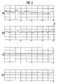
- the measured value N + W shown in FIG. 1 is subject to certain These fluctuations, which change from day to day and usually reach a minimum on a certain day, in the Federal Republic of Germany at night from Sunday to Monday.
- the fluctuations in the measured value N + W are caused by fluctuations in consumption, but also by fluctuations in losses, as shown in FIG.
- FIG. 2 The horizontal rows of points in FIG. 2 clearly show times of zero consumption, specifically in an area in which water is constantly escaping due to a leak.
- the zero consumption line runs on different days at different distances from the zero line of the writing strip of the recording device (dot recorder).
- the object is achieved by the method according to claim 1.
- Step 1 Optimal measurement time
- Step 2 Consider normal fluctuations in the measured value N + W in areas of different sizes.
- the ratios can vary from area to area in detail, taking the area size into account when determining water losses is an important step towards more precise water loss control. In particular, it is achieved that with a suitable choice of the measuring time and taking into account fluctuations in the measured value N + W, comparatively small leaks can be detected, which means that water loss control can also be carried out much more efficiently in larger areas.
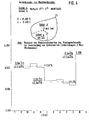
- FIG. 4 shows a control area A (25,000 U) and a smaller control area a (6,600 U) in the former control area A.
- the measured values N + W are regularly during the period (e.g. B..) On Mondays 2 4 5 - 15 3 measured and set the values obtained from this ratio and the average values of these ratios (4 values) formed over the month. Extreme values (vacation start, May 1st) were not taken into account in the comparison. It turned out that the ratios or their mean values only fluctuate by + 2.6 - + 3.0%, so that comparatively small changes, e.g. B. the elimination of pipe damage with a loss of 1.7 m 3 / h in area a a significant shift in the ratio
- the low-load time was chosen as the time of day in which the hourly consumption is less than 4.1666%. If one expresses the hourly consumption (24 measurement periods of a day) as a percentage of the daily consumption and all values less than 4.1666% are added up and divided by the corresponding number of hours, the result is a specific% value of the low-load period for each supply area, which is all the more the higher the water losses in the supply area are.
- control zones can be classified with regard to water losses after a first measurement of hourly consumption over a full 24 h from 00:00 to 24:00 a day.
- the combination offers the possibility of simple and efficient design of computer programs for evaluation, which are used either at a measuring point itself or in a central office. It is also essential here that the measuring point can be designed so that evaluations take place in it, so that only little information has to be transmitted to the control center.
- the other measurement periods mentioned can therefore be continuously queried and evaluated. However, it is sufficient if, when evaluating the first measurement period (according to the known method), there is suspicion of a leak, the others Query measurement periods. It has been confirmed that the consumption behavior over the course of the day is subject to statistical regularities, as a result of which emerging leaks also have a recognizable influence on measured values recorded at other times of the day. For example, it should be noted that during the day, even if in comparatively short periods of time, the same amount of water is almost always consumed in a supply area, due to special consumption times such as breakfast break, lunch break, main shopping time, etc. first and second specific measured value also a third measured value or even more such. B. 24 h measured values, see above, for water loss control.
- the assessment of the water losses in a control area is improved in particular by the fact that 7 daily mean values are formed from the measured values 1-3, etc., which compensates for day-specific deviations from an average amount of N + W.
- current measured values N + W of night consumption can be related to the 7 daily mean values of daily consumption, so that water losses due to the shifting of ratios become recognizable, similar to the explanations given in FIG. 4.
- the hourly consumption of each of the 24 hours of a day can also be used to control water loss due to the regularity of the daily consumption behavior.
- a distinction must be made between hours in which consumption fluctuates less than in other hours. So are suitable e.g. B. the morning hours 6:00 am - 8:00 am less than the afternoon hours 1:00 pm - 5:00 pm for an analysis of water losses.
- the observation of the hourly consumption is particularly important for the encirclement of damaged areas if this is to be carried out during the day.
- the control zone can be subdivided during the day by means of expulsions, so that the hourly consumption N + W, which is recorded by 2 measuring stations in each of the sub-control zones, provides information about which part the damage zone has occurred in the control zone and is to be circled further by gradual deportation, so that the fine location of the damage point can finally be carried out.
- N + W which is recorded by 2 measuring stations in each of the sub-control zones
- the statistical legality of consumer behavior over the course of the day offers several control options.
- the periods of maximum and half maximum consumption occurring statistically at the same times are suitable for such further measuring periods, especially since their measured values are often desired for other reasons.
- an evaluation at very specific times can lead to the same result.
- the invention can also be used in the same way for other meshed line networks.
- leaks can be detected in wastewater performance networks that cause infiltration (from the outside) and / or exfiltration (to the outside), which is undesirable.
Landscapes
- Physics & Mathematics (AREA)
- General Physics & Mathematics (AREA)
- Examining Or Testing Airtightness (AREA)
- Pipeline Systems (AREA)
Applications Claiming Priority (2)
| Application Number | Priority Date | Filing Date | Title |
|---|---|---|---|
| DE3233647 | 1982-09-10 | ||
| DE19823233647 DE3233647A1 (de) | 1982-09-10 | 1982-09-10 | Verfahren zur ueberpruefung eines vermaschten leitungsnetzes auf leckverluste |
Publications (2)
| Publication Number | Publication Date |
|---|---|
| EP0105229A2 true EP0105229A2 (fr) | 1984-04-11 |
| EP0105229A3 EP0105229A3 (fr) | 1986-10-15 |
Family
ID=6172930
Family Applications (1)
| Application Number | Title | Priority Date | Filing Date |
|---|---|---|---|
| EP83108926A Withdrawn EP0105229A3 (fr) | 1982-09-10 | 1983-09-09 | Procédé de contrôle de l'étanchéité d'un réseau de conduites |
Country Status (5)
| Country | Link |
|---|---|
| EP (1) | EP0105229A3 (fr) |
| JP (1) | JPS59131100A (fr) |
| AU (1) | AU1898783A (fr) |
| DE (1) | DE3233647A1 (fr) |
| ZA (1) | ZA836706B (fr) |
Cited By (6)
| Publication number | Priority date | Publication date | Assignee | Title |
|---|---|---|---|---|
| FR2616820A1 (fr) * | 1987-06-19 | 1988-12-23 | Gefs Holding Sa | Procede de detection precoce de zones de fuite dans un reseau de canalisations d'eau |
| DE19701317A1 (de) * | 1997-01-16 | 1998-07-23 | Peter Dipl Ing Renner | Leckerkennung in Rohrleitungssystemen |
| WO2002073139A2 (fr) * | 2001-03-09 | 2002-09-19 | Ads Corporation | Systeme et procede de surveillance des flux dans les egouts |
| WO2009022148A1 (fr) * | 2007-08-16 | 2009-02-19 | Ntnu Technology Transfer As | Appareil et procédé pour l'exploitation d'un pipeline |
| AU2007214283B2 (en) * | 2001-03-09 | 2010-09-16 | Ads Llc | Sewer flow monitoring method and system |
| FR3049623A1 (fr) * | 2016-04-04 | 2017-10-06 | Valcap Valence Capteur | Procede et dispositif informatiques de surveillance continue d'un reseau de canalisations d'eaux residuaires |
Families Citing this family (3)
| Publication number | Priority date | Publication date | Assignee | Title |
|---|---|---|---|---|
| DE4333095A1 (de) * | 1993-09-29 | 1995-03-30 | Gerhard Ritter | Verfahren zur Erkennung eines Lecks in einem Trinkwasser-Versorgungsnetz und Anordnung zur Anwendung des Verfahrens |
| DE19548514A1 (de) * | 1995-12-22 | 1997-06-26 | Bosch Siemens Hausgeraete | Wasserführendes, programmgesteuertes Haushaltgerät |
| EP2439496A1 (fr) * | 2010-10-06 | 2012-04-11 | Alcatel Lucent | Détection de perte dans des réseaux de distribution électrique |
Citations (2)
| Publication number | Priority date | Publication date | Assignee | Title |
|---|---|---|---|---|
| GB2017316A (en) * | 1978-02-22 | 1979-10-03 | Seba Mess Ortungstech | An improved method for determining leaks in water mains |
| DE2841674A1 (de) * | 1978-09-25 | 1980-05-22 | Heide Gerhard Dipl Ing | Verfahren und vorrichtung zur kontrolle von verlusten aus oeffentlichen wasserrohrnetzen |
-
1982
- 1982-09-10 DE DE19823233647 patent/DE3233647A1/de not_active Withdrawn
-
1983
- 1983-09-08 JP JP58165833A patent/JPS59131100A/ja active Pending
- 1983-09-09 ZA ZA836706A patent/ZA836706B/xx unknown
- 1983-09-09 AU AU18987/83A patent/AU1898783A/en not_active Abandoned
- 1983-09-09 EP EP83108926A patent/EP0105229A3/fr not_active Withdrawn
Patent Citations (2)
| Publication number | Priority date | Publication date | Assignee | Title |
|---|---|---|---|---|
| GB2017316A (en) * | 1978-02-22 | 1979-10-03 | Seba Mess Ortungstech | An improved method for determining leaks in water mains |
| DE2841674A1 (de) * | 1978-09-25 | 1980-05-22 | Heide Gerhard Dipl Ing | Verfahren und vorrichtung zur kontrolle von verlusten aus oeffentlichen wasserrohrnetzen |
Cited By (8)
| Publication number | Priority date | Publication date | Assignee | Title |
|---|---|---|---|---|
| FR2616820A1 (fr) * | 1987-06-19 | 1988-12-23 | Gefs Holding Sa | Procede de detection precoce de zones de fuite dans un reseau de canalisations d'eau |
| DE19701317A1 (de) * | 1997-01-16 | 1998-07-23 | Peter Dipl Ing Renner | Leckerkennung in Rohrleitungssystemen |
| WO2002073139A2 (fr) * | 2001-03-09 | 2002-09-19 | Ads Corporation | Systeme et procede de surveillance des flux dans les egouts |
| WO2002073139A3 (fr) * | 2001-03-09 | 2003-02-20 | Ads Corp | Systeme et procede de surveillance des flux dans les egouts |
| US6807494B2 (en) | 2001-03-09 | 2004-10-19 | Ads Corporation | Sewer flow monitoring method and system |
| AU2007214283B2 (en) * | 2001-03-09 | 2010-09-16 | Ads Llc | Sewer flow monitoring method and system |
| WO2009022148A1 (fr) * | 2007-08-16 | 2009-02-19 | Ntnu Technology Transfer As | Appareil et procédé pour l'exploitation d'un pipeline |
| FR3049623A1 (fr) * | 2016-04-04 | 2017-10-06 | Valcap Valence Capteur | Procede et dispositif informatiques de surveillance continue d'un reseau de canalisations d'eaux residuaires |
Also Published As
| Publication number | Publication date |
|---|---|
| AU1898783A (en) | 1984-03-15 |
| JPS59131100A (ja) | 1984-07-27 |
| DE3233647A1 (de) | 1984-03-15 |
| ZA836706B (en) | 1984-04-25 |
| EP0105229A3 (fr) | 1986-10-15 |
Similar Documents
| Publication | Publication Date | Title |
|---|---|---|
| DE2341087C3 (de) | Automatische Brandmeldeanlage | |
| EP0365901B1 (fr) | Système de contrÔle d'une pluralité de postes de travail des machines textiles | |
| DE2436373A1 (de) | Fehlerortungsverfahren fuer ein vierdraht-traegerfrequenzsystem | |
| EP0177019A2 (fr) | Dispositif de transmission de données comprenant un réseau de données à structure en arbre | |
| DE3007762A1 (de) | Signalverarbeitungseinrichtung | |
| EP0105229A2 (fr) | Procédé de contrôle de l'étanchéité d'un réseau de conduites | |
| EP1145088A1 (fr) | Controle de la qualite dans une fabrication | |
| EP3528162B1 (fr) | Procédé de détection des états de fonctionnement anormaux | |
| DE4317746A1 (de) | Verfahren und Einrichtung zur Raumfilterung | |
| DE202013009956U1 (de) | Vorrichtung und Messsystem zur automatischen Charakterisierung und Überwachung eines elektrischen Netzes oder eines Stromnetzabschnitts eines elektrischen Netzes oder einer elektrischen Anlage | |
| DE3118767C2 (de) | Verfahren zur fehlerarmen Peilwinkelermittlung | |
| CH686915A5 (de) | Verfahren zur Vermeidung von Fehlalarmen in einem Brandmeldesystem, und Brandmeldesystem zur Durchfuehrung des Verfahrens. | |
| DE102012104162A1 (de) | Verfahren und System zum Überwachen des Energie- oder Wasserverbrauchs | |
| DE19637843C2 (de) | Verfahren zur Identifizierung eines Verkehrsteilnehmers und Anordnung zur Durchführung des Verfahrens | |
| DE2820097B2 (de) | Verfahren zur Bestimmung der Häufigkeit von Garnfehlern | |
| DE4342136B4 (de) | Verfahren zur Diagnose einer Lambda-Sonde | |
| DE19925580B4 (de) | Pegel- und Peilwinkel-basierte Detektion und Segmentierung von Sendungen im HF-Bereich | |
| DE4228934C2 (de) | Vorrichtung zur Bestimmung des Vertrauensbereichs von Perzentil-Meßwerten kontinuierlicher stochastischer Schallsignale | |
| DE102008062696A1 (de) | Verfahren zur Messdatenverarbeitung und Messgerät | |
| EP1526621B1 (fr) | Procédé d'identification des défauts de terre intermittents | |
| DE19640431B4 (de) | Verfahren zur Ermittlung einer Datumsangabe aus einem Zeitsignal | |
| DE3132009C2 (fr) | ||
| DE2929324A1 (de) | Verfahren zur ermittlung der lebensdauer von siliciumnitridgegenstaenden | |
| DE19937894B4 (de) | Verfahren zur Bewertung und Verfahren zur Optimierung von Verkehrsstörungserkennungsverfahren | |
| DE19850579C2 (de) | Verfahren zum Betreiben eines Meßumformers |
Legal Events
| Date | Code | Title | Description |
|---|---|---|---|
| PUAI | Public reference made under article 153(3) epc to a published international application that has entered the european phase |
Free format text: ORIGINAL CODE: 0009012 |
|
| AK | Designated contracting states |
Designated state(s): AT BE CH DE FR GB IT LI LU NL SE |
|
| 17P | Request for examination filed |
Effective date: 19840907 |
|
| PUAL | Search report despatched |
Free format text: ORIGINAL CODE: 0009013 |
|
| AK | Designated contracting states |
Kind code of ref document: A3 Designated state(s): AT BE CH DE FR GB IT LI LU NL SE |
|
| STAA | Information on the status of an ep patent application or granted ep patent |
Free format text: STATUS: THE APPLICATION IS DEEMED TO BE WITHDRAWN |
|
| 18D | Application deemed to be withdrawn |
Effective date: 19860401 |