EP0104415A1 - Düsenspinnmaschine - Google Patents
Düsenspinnmaschine Download PDFInfo
- Publication number
- EP0104415A1 EP0104415A1 EP83108206A EP83108206A EP0104415A1 EP 0104415 A1 EP0104415 A1 EP 0104415A1 EP 83108206 A EP83108206 A EP 83108206A EP 83108206 A EP83108206 A EP 83108206A EP 0104415 A1 EP0104415 A1 EP 0104415A1
- Authority
- EP
- European Patent Office
- Prior art keywords
- spinning
- unit
- nozzle
- spinning machine
- nozzle spinning
- Prior art date
- Legal status (The legal status is an assumption and is not a legal conclusion. Google has not performed a legal analysis and makes no representation as to the accuracy of the status listed.)
- Withdrawn
Links
Images
Classifications
-
- D—TEXTILES; PAPER
- D01—NATURAL OR MAN-MADE THREADS OR FIBRES; SPINNING
- D01H—SPINNING OR TWISTING
- D01H1/00—Spinning or twisting machines in which the product is wound-up continuously
- D01H1/14—Details
- D01H1/16—Framework; Casings; Coverings ; Removal of heat; Means for generating overpressure of air against infiltration of dust; Ducts for electric cables
-
- D—TEXTILES; PAPER
- D01—NATURAL OR MAN-MADE THREADS OR FIBRES; SPINNING
- D01H—SPINNING OR TWISTING
- D01H1/00—Spinning or twisting machines in which the product is wound-up continuously
- D01H1/11—Spinning by false-twisting
- D01H1/115—Spinning by false-twisting using pneumatic means
Definitions
- the invention relates to a nozzle spinning machine consisting of at least one and preferably a plurality of nozzle spinning stations, each nozzle spinning station being designed to receive a spinning can and a drafting device for taking over and stretching a sliver taken from the spinning can, a nozzle spinning unit downstream of the drafting device in the working direction, for producing a spun Yarns and a winding unit for the spun yarn.
- nozzle spinning As is known, one of the advantages of so-called nozzle spinning is that tapes can be spun directly into yarn.
- belts are delivered in cans, which means that the can template is included in the construction concept of the jet spinning machine.
- the jet spinning machines previously brought onto the market are designed in such a way that the can template is arranged on the back and the spin units on the front or operating side of the jet spinning machine.
- the sliver taken from a spinning can is fed via the machine to a drafting system upstream of the actual spinning unit.
- the spinning unit arranged after the drafting unit delivers the finished yarn to a winding unit provided underneath.
- the main disadvantage of this construction concept is that the jet spinning machines require a relatively large amount of space per unit yarn weight produced. This disadvantage is particularly significant in the production of fine yarns, such as those produced by jet spinning machines, since the specific space requirement for fine yarns is generally high.
- a further disadvantage is that the winding device is arranged in a manner that is inconvenient to use and maintenance.
- the invention is therefore based on the object of designing a nozzle spinning machine of the type mentioned in such a way that more yarn can be produced under more convenient conditions with the same amount of space available, or that the space requirement and operating effort can be reduced in the production of the same amount of yarn.
- This object is achieved in that the spinning can, the drafting unit, the nozzle spinning unit and the winding unit are located on the operating side of the nozzle spinning machine for each nozzle spinning station, and in that the spinning can is arranged below and the winding unit above the drafting unit and the nozzle spinning unit. In this way, the arrangement of the can template on the back of the jet spinning machine is avoided and the winding unit is placed higher, so that the overall space requirement is reduced and the ease of use is largely improved, and also because the previous deep arrangement of the unraveling device is avoided.
- the drafting system and the spinning unit can be arranged essentially in a horizontal or vertical position or in an intermediate position directed obliquely upwards. This means that the sliver does not have to travel long distances from the can to the drafting system on special guides.
- a nozzle spinning machine which consists of a plurality of nozzle spinning stations arranged in a row, that a conveying device for the further transport of the finished bobbins or for the delivery of the empty bobbin tubes extends over the entire length of the nozzle spinning machine extends next to the winding units.
- the conveyor is arranged on the side of the winding units facing away from the operating side.
- a conveying device is expediently provided for the further transport of the finished bobbins or for the delivery of the empty spinning tubes and is arranged above the nozzle spinning machine over the length of the same between the winding units.
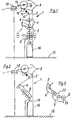
- 1 has a machine frame 2 (indicated by a dash-dotted line), a drafting system 3, a nozzle spinning unit 4 and a winding unit 5.
- the drafting unit 3, the nozzle spinning unit 4 and the winding unit 5 are known per se.
- the drafting system 3 comprises an input roller pair 6 and an output roller pair 7.
- the nozzle spinning unit 4 comprises a swirl sensor 8 and an outlet roller pair 9.
- the winding unit 5 includes a deflection element 10, a thread changer 11, a drive roller 12 and a spool 13, the latter on a spool holder 14 is rotatably mounted.
- the finished yarn delivered by the pair of outlet rollers 9 is wound up in the winding unit 5.
- the spinning can 16, the drafting device 3, the spinning nozzle unit 4 and the take-up unit 5 together form a D üsenspinn- station. Normally, several such nozzle spinning stations are arranged in a row.
- upward spinning in which the sliver can 16 is below and the winding unit above the drafting unit 3 and the spinning unit 4, a conveyor belt 19 can be provided on the upper part of the machine frame 2, onto which the finished ones Coils are delivered for further transport.
- the drafting unit 3 and the nozzle spinning unit 4 can be in a horizontal position (indicated by dash-dotted lines in Fig. 1), vertical position (in Fig. 1 with solid lines) Lines shown) or an obliquely upward intermediate layer (Fig. 2) can be provided.
- the drafting system 3 and the spinning unit 4 are generally arranged in alignment (as shown in FIGS. 1 and 2). However, this arrangement is not mandatory for the implementation of the inventive concept.
- the spinning machine 1 has a corresponding machine frame 2 '.
- the inclined arrangement offers, compared to the vertical or horizontal arrangement, the advantage that the operability can be optimized in relation to the manual bobbin change in the upper part of the machine, as well as in relation to the insertion of the yarn into the drafting system and into the spinning unit.
- An in this respect an optimum tilt range, depending on the length of the drafting arrangement and the jet spinning unit between 25 and 45 0, where the tilt (not shown) through one of the bottom surface 15 and an imaginary connecting line shown in Fig. 3 with a broken line 20 included angle is determined .
- the line 20 connects the clamping line of the input rollers 6 with the clamping line of the output rollers 9. This connecting line or line 20 lies in an imaginary plane perpendicular to the floor surface 15.
- Fig. 3 it is further shown that not only, as shown in Figs. 1 and 2, drafting systems with a straight but also with a kinked yarn course can be used according to the invention.
- the drafting system with a twisted course of the yarn is designated 3 '.
- the arrangement according to the invention can be used on a single-sided or on a double-sided nozzle spinning machine.
- the arrangement according to the invention can be provided rotated by 180 ° on the opposite side of the machine.
- the sliver cans 16 are preferably on the operating floor 15.
Landscapes
- Engineering & Computer Science (AREA)
- Mechanical Engineering (AREA)
- Textile Engineering (AREA)
- Spinning Or Twisting Of Yarns (AREA)
Applications Claiming Priority (2)
| Application Number | Priority Date | Filing Date | Title |
|---|---|---|---|
| CH5102/82 | 1982-08-27 | ||
| CH510282 | 1982-08-27 |
Publications (1)
| Publication Number | Publication Date |
|---|---|
| EP0104415A1 true EP0104415A1 (de) | 1984-04-04 |
Family
ID=4287967
Family Applications (1)
| Application Number | Title | Priority Date | Filing Date |
|---|---|---|---|
| EP83108206A Withdrawn EP0104415A1 (de) | 1982-08-27 | 1983-08-19 | Düsenspinnmaschine |
Country Status (5)
| Country | Link |
|---|---|
| EP (1) | EP0104415A1 (enExample) |
| JP (1) | JPS5943126A (enExample) |
| DE (1) | DE8322304U1 (enExample) |
| FR (1) | FR2532336A3 (enExample) |
| IT (1) | IT8322300U1 (enExample) |
Cited By (2)
| Publication number | Priority date | Publication date | Assignee | Title |
|---|---|---|---|---|
| EP0372255A1 (de) * | 1988-11-23 | 1990-06-13 | Maschinenfabrik Rieter Ag | Düsenspinnvorrichtung |
| EP3103750A1 (en) * | 2015-06-11 | 2016-12-14 | Murata Machinery, Ltd. | Yarn winding machine and spinning machine |
Families Citing this family (2)
| Publication number | Priority date | Publication date | Assignee | Title |
|---|---|---|---|---|
| DE10251727A1 (de) * | 2002-11-05 | 2004-05-13 | Deutsches Institut für Textil- und Faserforschung Stuttgart - Stiftung des öffentlichen Rechts | Verfahren und Vorrichtung zur Herstellung von Flyerlunte |
| JP2012031523A (ja) * | 2008-11-28 | 2012-02-16 | Murata Mach Ltd | 紡績機 |
Citations (3)
| Publication number | Priority date | Publication date | Assignee | Title |
|---|---|---|---|---|
| DE2128751A1 (en) * | 1971-06-09 | 1972-12-21 | Pensenskij Nautschno lssledowatels kij experimentalno konstruktorskij in stitut prjadilnych maschin, Ternowka (Sowjetunion) | Ringless spinning machine - with material flow upwards from supply at base through spinning chamber to winding |
| DE2317639A1 (de) * | 1973-04-07 | 1974-10-17 | Krupp Gmbh | Offen-end-spinnmaschine mit kannenspeisung |
| FR2355101A1 (fr) * | 1976-06-17 | 1978-01-13 | Inst Legkogo Textilnogo Mashin | Dispositif de filage a bout ouvert |
-
1983
- 1983-07-06 FR FR8311242A patent/FR2532336A3/fr active Granted
- 1983-07-07 IT ITMI1983U22300U patent/IT8322300U1/it unknown
- 1983-08-02 JP JP58140623A patent/JPS5943126A/ja active Pending
- 1983-08-02 DE DE19838322304U patent/DE8322304U1/de not_active Expired
- 1983-08-19 EP EP83108206A patent/EP0104415A1/de not_active Withdrawn
Patent Citations (3)
| Publication number | Priority date | Publication date | Assignee | Title |
|---|---|---|---|---|
| DE2128751A1 (en) * | 1971-06-09 | 1972-12-21 | Pensenskij Nautschno lssledowatels kij experimentalno konstruktorskij in stitut prjadilnych maschin, Ternowka (Sowjetunion) | Ringless spinning machine - with material flow upwards from supply at base through spinning chamber to winding |
| DE2317639A1 (de) * | 1973-04-07 | 1974-10-17 | Krupp Gmbh | Offen-end-spinnmaschine mit kannenspeisung |
| FR2355101A1 (fr) * | 1976-06-17 | 1978-01-13 | Inst Legkogo Textilnogo Mashin | Dispositif de filage a bout ouvert |
Cited By (4)
| Publication number | Priority date | Publication date | Assignee | Title |
|---|---|---|---|---|
| EP0372255A1 (de) * | 1988-11-23 | 1990-06-13 | Maschinenfabrik Rieter Ag | Düsenspinnvorrichtung |
| EP3103750A1 (en) * | 2015-06-11 | 2016-12-14 | Murata Machinery, Ltd. | Yarn winding machine and spinning machine |
| CN106241495A (zh) * | 2015-06-11 | 2016-12-21 | 村田机械株式会社 | 纱线卷取机以及纺纱机械 |
| CN106241495B (zh) * | 2015-06-11 | 2019-07-12 | 村田机械株式会社 | 纱线卷取机以及纺纱机械 |
Also Published As
| Publication number | Publication date |
|---|---|
| JPS5943126A (ja) | 1984-03-10 |
| FR2532336B3 (enExample) | 1984-06-22 |
| DE8322304U1 (de) | 1983-11-10 |
| IT8322300V0 (it) | 1983-07-07 |
| IT8322300U1 (it) | 1985-01-07 |
| FR2532336A3 (fr) | 1984-03-02 |
Similar Documents
| Publication | Publication Date | Title |
|---|---|---|
| DE2455892B2 (de) | Textilmaschine | |
| DE3935705A1 (de) | Mehrfachfaden aus gesponnenen faeden und verfahren und vorrichtung zur herstellung des mehrfachfadens | |
| DE1510234A1 (de) | Bandspeicheranlage | |
| EP0204202B1 (de) | Anordnung zum Transportieren von Kannen für Textilmaterial | |
| DE2744424B2 (de) | Spiniunaschinenrahmen | |
| DE3501796C2 (enExample) | ||
| EP0104415A1 (de) | Düsenspinnmaschine | |
| CH695777A5 (de) | Vorrichtung zum Füllen einer Kanne mit länglichem Querschnitt mit Faserband. | |
| DE10320452A1 (de) | Verfahren zur Faserbandbehandlung in der Kämmerei, Kannengestell für Kämmereimaschinen sowie Maschine in der Kämmerei | |
| DE19501163C1 (de) | Streckwerk für Spinnmaschinen mit einer Leiteinrichtung zum Zuführen eines Kernfadens | |
| EP0425803B1 (de) | Vorrichtung zum Zuführen von Faserbändern zu einer textilverarbeitenden Maschine | |
| CH648874A5 (de) | Vorrichtung zur herstellung von effektgarn. | |
| CH626926A5 (enExample) | ||
| DE69026050T2 (de) | Verfahren zum Auswechseln von Vorgarnspulen in Ringspinnmaschinen | |
| DE4038231A1 (de) | Verfahren und spinnmaschine zum verspinnen von faserbaendern | |
| DE3319559A1 (de) | Streckvorrichtung in einer spinnmaschine | |
| DE68916703T2 (de) | Garntexturierungsmaschine. | |
| DE4109022C2 (de) | Spinnmaschine zum Erspinnen von Garnen aus Faserbändern | |
| DE102019128326A1 (de) | Verdichtungsvorrichtung für ein Streckwerk einer Spinnmaschine sowie Streckwerk für eine Verdichtungsvorrichtung | |
| DE4109097C2 (de) | Spinnmaschine | |
| EP0372255A1 (de) | Düsenspinnvorrichtung | |
| WO2007036335A1 (de) | Zuführverfahren und zuführeinrichtung für vorlagespulen | |
| DE4129575C2 (de) | Verfahren zum Betreiben einer Ringspinnmaschine und Maschinenanlage | |
| DE4140238A1 (de) | Spinnmaschine mit auf einer maschinenseite in einer reihe nebeneinander angeordneten spinnstellen | |
| EP4567170A1 (de) | Verdichtereinrichtung |
Legal Events
| Date | Code | Title | Description |
|---|---|---|---|
| PUAI | Public reference made under article 153(3) epc to a published international application that has entered the european phase |
Free format text: ORIGINAL CODE: 0009012 |
|
| AK | Designated contracting states |
Designated state(s): CH DE FR GB IT LI NL |
|
| 17P | Request for examination filed |
Effective date: 19840313 |
|
| STAA | Information on the status of an ep patent application or granted ep patent |
Free format text: STATUS: THE APPLICATION IS DEEMED TO BE WITHDRAWN |
|
| 18D | Application deemed to be withdrawn |
Effective date: 19850503 |
|
| RIN1 | Information on inventor provided before grant (corrected) |
Inventor name: STALDER, HERBERT Inventor name: BRINER, EMIL |