EP0104333B1 - Verfahren und Einrichtung zur gleichzeitigen Aufnahme einer Mehrzahl von FT-IR Signalen - Google Patents
Verfahren und Einrichtung zur gleichzeitigen Aufnahme einer Mehrzahl von FT-IR Signalen Download PDFInfo
- Publication number
- EP0104333B1 EP0104333B1 EP83106496A EP83106496A EP0104333B1 EP 0104333 B1 EP0104333 B1 EP 0104333B1 EP 83106496 A EP83106496 A EP 83106496A EP 83106496 A EP83106496 A EP 83106496A EP 0104333 B1 EP0104333 B1 EP 0104333B1
- Authority
- EP
- European Patent Office
- Prior art keywords
- circuit means
- odd
- signal
- analog
- scan
- Prior art date
- Legal status (The legal status is an assumption and is not a legal conclusion. Google has not performed a legal analysis and makes no representation as to the accuracy of the status listed.)
- Expired
Links
- 238000000034 method Methods 0.000 title claims description 17
- 238000005033 Fourier transform infrared spectroscopy Methods 0.000 claims description 12
- 238000006243 chemical reaction Methods 0.000 claims description 5
- 230000008878 coupling Effects 0.000 claims 4
- 238000010168 coupling process Methods 0.000 claims 4
- 238000005859 coupling reaction Methods 0.000 claims 4
- 238000001228 spectrum Methods 0.000 description 26
- 238000010586 diagram Methods 0.000 description 5
- 230000003595 spectral effect Effects 0.000 description 5
- 230000003287 optical effect Effects 0.000 description 4
- 230000005855 radiation Effects 0.000 description 4
- 230000008859 change Effects 0.000 description 3
- 238000013480 data collection Methods 0.000 description 3
- 238000009615 fourier-transform spectroscopy Methods 0.000 description 3
- 230000005540 biological transmission Effects 0.000 description 2
- 239000002131 composite material Substances 0.000 description 2
- 238000012937 correction Methods 0.000 description 2
- 238000013461 design Methods 0.000 description 2
- 238000002329 infrared spectrum Methods 0.000 description 2
- 230000008569 process Effects 0.000 description 2
- 230000009466 transformation Effects 0.000 description 2
- 238000012935 Averaging Methods 0.000 description 1
- 235000013175 Crataegus laevigata Nutrition 0.000 description 1
- 238000013459 approach Methods 0.000 description 1
- 230000008901 benefit Effects 0.000 description 1
- 230000001427 coherent effect Effects 0.000 description 1
- 238000013500 data storage Methods 0.000 description 1
- 230000009977 dual effect Effects 0.000 description 1
- 230000005670 electromagnetic radiation Effects 0.000 description 1
- 238000001819 mass spectrum Methods 0.000 description 1
- 210000000826 nictitating membrane Anatomy 0.000 description 1
- 230000004044 response Effects 0.000 description 1
- 238000012552 review Methods 0.000 description 1
- 238000005070 sampling Methods 0.000 description 1
- 238000004611 spectroscopical analysis Methods 0.000 description 1
- 239000000126 substance Substances 0.000 description 1
- 238000012360 testing method Methods 0.000 description 1
Images


Classifications
-
- G—PHYSICS
- G01—MEASURING; TESTING
- G01J—MEASUREMENT OF INTENSITY, VELOCITY, SPECTRAL CONTENT, POLARISATION, PHASE OR PULSE CHARACTERISTICS OF INFRARED, VISIBLE OR ULTRAVIOLET LIGHT; COLORIMETRY; RADIATION PYROMETRY
- G01J3/00—Spectrometry; Spectrophotometry; Monochromators; Measuring colours
- G01J3/28—Investigating the spectrum
- G01J3/45—Interferometric spectrometry
- G01J3/453—Interferometric spectrometry by correlation of the amplitudes
Definitions
- This invention relates to spectroscopy and more particularly to Fourier Transform spectroscopy in which an interferometer is used.
- Interferometers have been used for many years to measure and to analyze the frequency spectra of electromagnetic radiation.
- the basic principles and general operation of interferometers for Fourier Transform Infrared (FT-IR) signals are well known, and can be found in many textbooks and review papers on the subject such as the ones written by R. J. Bell, "Introductory Fourier Transform Spectroscopy", Academic Press, 1972; or P. R. Griffiths, "Chemical Infrared Fourier Transform Spectroscopy", John Wiley & Sons, 1974. It is commonly accepted that in operation an FT-IR Spectrometer records sample and reference data in sequential fashion. While this operation is adequate for most applications, there are some circumstances in which these characteristics present a limitation.
- the apparatus comprises switching circuit means having at least two signal terminals, a first and a second control circuit input terminal and an output terminal, a Sample-and-Hold (S&H) circuit is connected between the output terminal of the switching means and the input terminal of an Analog-to-Digital Converter (ADC), a first control signal is provided for synchronizing the operation of the interferometer and the control circuits and a second control signal is operable to define data acquisition intervals, the first control signal is coupled to the first control circuit input terminal of the switching circuit means to reset the switching circuit means to a predetermined state, the second control signal is coupled to the second control circuit input terminal to switch the state of the switching circuit means for each of the signal defining intervals so that the data samples for each of the input signals are interleaved, computing circuit means is provided to receive the digital data from the ADC
- the computing circuit means is then operable under program control for storing said data in a sequence of storage locations in a split form, wherein the first signal (DIGITIZED ANALOG 2) is stored in the even storage locations during the first scan (EVEN 1st) and in the odd storage locations during the second scan ODD 2nd) and the other signal (DIGITIZED ANALOG 1) is stored in the odd locations during the first scan (ODD 1st) and in the even locations during the second scan (EVEN 2nd), and to access the digital data so that all data samples for the same input signals are combined to produce an interferogram for each of the input signals, under program control in accordance with an algorithm expressed as the sum of the Even 1st and Odd 2nd divided by the sum of the Even 2nd and the Odd 1st.
- the switching circuit means comprises essentially a double-pole-double-throw circuit arrangement followed by a single-pole-double-throw circuit arrangement.
- the digital data is stored in odd and even storage locations in a split form and the digital data is recombined under program control in accordance with the algorithm expressible as the sum of the Even 1st and the Odd 2nd divided by the sum of the Even 2nd and the Odd 1st or
- Our invention provides apparatus and a method for simultaneously recording multiple Fourier Transform Infrared (FT-IR) signals.
- the apparatus and method require an interferometer.
- FT-IR Fourier Transform Infrared
- interferometer In the following description, a Michelson type interferometer is chosen for purposes of example, but it will be understood that the specific example is not intended to constitute a limitation on the general utility of the invention.
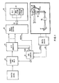
- a reference laser 10 produces coherent radiation which is directed to beam splitter 11 where it is split into two beams. Each beam half is directed to one of the mirrors 12, 13. Mirror 12 is fixed in position, and mirror 13 is moveable along a linear path so that the optical path including moveable mirror 13 has a variable path length (shown dotted in Fig. 1). Each beam half is reflected from the appropriate mirror 12 or 13 back to beam splitter 11 where the beams interfere to form a composite beam which is a function of moveable mirror 13 position. The composite beam is directed to laser detector 14 which converts the beam into an electrical signal. This signal LAS (see Fig.
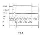
- a digital signal XA (see Fig. 8) is derived from these zero crossings which provides the basic timing for the End of Conversion (EOC) digital signal which defines the data acquisition intervals.
- a white light source '19 is directed over the same optical path including beam splitter 11, fixed mirror 12 and moveable mirror 13. The interference pattern is detected by white light detector 18. The center burst (largest amplitude) of the output of the white light detector 18 is used to generate the digital signal Take Data (TKDA) (see Fig. 8) which serves to synchronize the interferometer operation with the associated control circuits.
- TKDA Digital Signal Take Data
- Infrared radiation from a broadband source 15 is directed along a path to beamsplitter 11, traverses the interferometer, and is directed to a sample chamber 16 and to an infrared detector 17.
- the infrared detector detects the radiation intensity.
- the detector output signal is therefore a measure of the incident intensities of all spectral components and the detector spectral responsivity.
- the detector signal amplitude as a function of the optical path difference is called an interferogram, and an example of one interferogram is shown in Fig. 2.
- An additional IR interferogram is shown in Fig. 8 which is greatly compressed in scale relative to the other signals shown there.
- the interferogram contains the modulated components of the detected IR radiation and is related to the spectrum via the process of Fourier Transformation.
- the analog IR interferogram signal is sampled at equal distances derived from the laser signal XA and is transferred to a processor in digitized form. If necessary, the signal-to-noise ratio of the digital data is increased by coherently adding amplitudes of many inter f erograms.
- the digitized data are stored in the processor storage until all the signals for an interferogram are received by the processor. Once data collection is completed, the digitized data is operated on by means of a suitable algorithm to produce the IR spectrum of interest. In the art the process is known as the Fourier Transform. In this disclosure Fourier Transform is meant to include the combination of apodization, fast Fourier transformation, and phase correction to produce an IR spectrum from a given interferogram.
- the spectrum of the interferogram of Fig. 2 is shown in Fig. 3.
- a spectrum obtained in such a manner contains the data of interest along with unwanted spectral features of the IR source 15, the interferometer components 11-14, sample chamber 16 and detector 17. These unwanted spectral features can be removed via a ratio with a suitable reference.
- the reference is a spectrum of the instrument without the sample, recorded sequentially to the sample spectrum.
- FIG. 4 A specific embodiment of a switching circuit which permits two spectra to be recorded substantially simultaneously is shown in Fig. 4.
- the two signals ANALOG 1 and ANALOG 2 are coupled to an analog switch 20, which is reset at the beginning of each scan by the signal TKDA which is coupled to the reset terminal of analog switch 20.
- the signal Take Data (TKDA) goes high at a precise time for each scan start.
- a scan is defined as the sequence of movement of moveable mirror 13 from the full line to its dotted line position.
- the signal FORWARD (Fig. 8) is generated by a sensor (not shown) which detects when moveable mirror 13 has returned to the full line position shown in Fig. 1.
- the TRIGGER DELAY is a setting under control of the operator so that the precise timing of TKDA can be set in this manner as shown in Fig. 8.
- the ANALOG 1 and ANALOG 2 signals are alternately coupled to Sample and Hold (S&H) circuit 22 by means of the End of Conversion (EOC) signal coupled to the SWITCH STATE input terminal of analog switch 20.
- S&H circuit 22 is coupled to the Analog to Digital Converter (ADC) 24 to digitize the analog signal under control of ADC control 26 (Fig. 1).
- ADC 24 is temporarily stored in Data Output Buffer 28, and at the appropriate time is coupled over channel 38 to Processor 32 under control of the signal NDRDY. Since an EOC pulse corresponds to each data point taken, the resulting interferogram is composed of alternately DIGITIZED ANALOG 1 and DIGITIZED ANALOG 2 data. As shown in Fig.
- the data points are digitized and stored in sequential storage locations.
- the digitized data points for the ANALOG 1 signal are stored in the odd storage locations as shown in Fig. 6, and the digitized data points for ANALOG 2 are stored in the even storage locations.
- the digitized signals corresponding to the data points of the ANALOG 1 and ANALOG 2 data are stored in processor data storage means 34 in sequential storage locations.
- the Fourier Transform of the stored interferograms is executed to produce the respective spectra by accessing the data stored in odd storage locations for the DIGITIZED ANALOG 1 interferogram and by accessing the data stored in even storage locations for the DIGITIZED ANALOG 2 interferogram.
- the embodiment shown in Fig. 4 has been shown to provide the spectra of two signals recorded simultaneously as described above.
- the embodiment shown in Fig. 5 represents a further refinement in the switching circuit that permits more accurate spectra to be obtained in most cases in which two spectra are obtained simultaneously.
- the even and odd interferograms have slightly different amplitudes because of digitization.
- two separate scans are taken so that DIGITIZED ANALOG 1 goes into the odd storage locations in the first scan, but into even storage locations in the second scan.
- a double-pole double-throw (DPDT) analog switch 30 is coupled to receive the two input signals ANALOG 1 and ANALOG 2.
- the analog switch 30 is coupled to analog switch 20, so that in a first position the ANALOG 1 signal is coupled to analog switch 20 in its RESET state (as shown in Fig. 5).
- the signal TKDA is coupled to the SWITCH STATE input of analog switch 30 to change the switch to a second state (opposite to that shown in Fig. 5) in which the ANALOG 2 input is coupled to analog switch 20 in its RESET state (as shown in Fig. 5). It can be seen that when switch 30 is in the RESET position, the DIGITIZED ANALOG 1 signals are stored in a first data file in the odd storage locations and the DIGITIZED ANALOG 2 signals are stored in the even storage locations.
- switch 30 is changed to its second state and in this case the DIGITIZED ANALOG 2 signals are stored in odd storage locations and the DIGITIZED ANALOG 1 signals are stored in even storage locations in a second data file determined prior to data collection.
- two full inteferograms are collected and stored separately.
- switch 30 when switch 30 is in its first state (shown In Fig. 5), interferogram one is recorded and when switch 30 is in state 2 interferogram two is recorded.
- the data address to store the interferograms is changed so that interferogram one is always stored and co-added with interferogram one data and interferogram two is always stored and co-added with interferogram two data collected previously.
- software to handle the separate interferograms must be available.
- One such program is called COLLECT DUAL which collects interferograms into two storage disk files in an alternating fashion.
- the switching can be done in a digital fashion in the embodiment shown in Fig. 7.
- the ANALOG 1 signal is coupled into a first S&H circuit 22, the output of which is coupled to an ADC 24.
- the output of ADC 24 is coupled to a series of tri state devices 36 and the output of devices 36 is gated on to channel 38 for transmission to processor 32.
- a similar path is provided forthe ANALOG 2 signal.
- Control logic 40 provides control signals to direct the conversion of the appropriate one of the input signals according to the chosen control method. In the Fig.
- control logic 40 is reset to a predetermined state by the signal TKDA so that control logic 40 is operable in response to the first EOC pulse received on input line 42 to energize the S&H 22 and ADC 24 for the ANALOG 1 signal.
- the appropriate tri-state devices are energized to gate the digital data to channel 38 for transmission to processor 32.
- control logic 40 is operable to energize the S&H 22 and ADC 24 forthe ANALOG 2 signal.
Landscapes
- Physics & Mathematics (AREA)
- Spectroscopy & Molecular Physics (AREA)
- General Physics & Mathematics (AREA)
- Spectrometry And Color Measurement (AREA)
Claims (8)
Applications Claiming Priority (2)
| Application Number | Priority Date | Filing Date | Title |
|---|---|---|---|
| US06/413,034 US4511986A (en) | 1982-08-30 | 1982-08-30 | Method and apparatus for simultaneously recording multiple FT-IR signals |
| US413034 | 2006-04-27 |
Publications (3)
| Publication Number | Publication Date |
|---|---|
| EP0104333A2 EP0104333A2 (de) | 1984-04-04 |
| EP0104333A3 EP0104333A3 (en) | 1984-11-28 |
| EP0104333B1 true EP0104333B1 (de) | 1987-10-28 |
Family
ID=23635531
Family Applications (1)
| Application Number | Title | Priority Date | Filing Date |
|---|---|---|---|
| EP83106496A Expired EP0104333B1 (de) | 1982-08-30 | 1983-07-04 | Verfahren und Einrichtung zur gleichzeitigen Aufnahme einer Mehrzahl von FT-IR Signalen |
Country Status (4)
| Country | Link |
|---|---|
| US (1) | US4511986A (de) |
| EP (1) | EP0104333B1 (de) |
| JP (1) | JPS5940221A (de) |
| DE (1) | DE3374217D1 (de) |
Families Citing this family (14)
| Publication number | Priority date | Publication date | Assignee | Title |
|---|---|---|---|---|
| DE3484668D1 (de) * | 1983-08-30 | 1991-07-11 | Perkin Elmer Corp | Spektralphotometer. |
| US5078501A (en) * | 1986-10-17 | 1992-01-07 | E. I. Du Pont De Nemours And Company | Method and apparatus for optically evaluating the conformance of unknown objects to predetermined characteristics |
| US5159474A (en) * | 1986-10-17 | 1992-10-27 | E. I. Du Pont De Nemours And Company | Transform optical processing system |
| US4855930A (en) * | 1987-03-27 | 1989-08-08 | Chimerix Corporation | Method and appartatus for improved time-resolved fluorescence spectroscopy |
| JPH0227226A (ja) * | 1988-07-18 | 1990-01-30 | Fuji Electric Co Ltd | フーリエ変換分光器のデータ処理方式 |
| GB2235284A (en) * | 1989-03-23 | 1991-02-27 | Jeremy Kenneth Arthur Everard | Optical spectrum analyser |
| DE3935617A1 (de) * | 1989-10-26 | 1991-05-02 | Bruker Analytische Messtechnik | Infrarot-fouriertransformations-spektrometer |
| JPH063401B2 (ja) * | 1989-12-29 | 1994-01-12 | 株式会社島津製作所 | 干渉分光光度計 |
| US5170223A (en) * | 1990-12-03 | 1992-12-08 | Advanced Fuel Research, Inc. | Device for blocking of divergent radiation, as in spectroscopy and instrument and method utilizing same |
| DE4107549C2 (de) * | 1991-03-08 | 1995-01-12 | Deutsche Forsch Luft Raumfahrt | Verfahren zum Betrieb und zur Wellenzahlkalibrierung eines Interferometers nach Michelson |
| DE69631530T2 (de) * | 1996-10-09 | 2004-07-08 | Perkin-Elmer Ltd., Beaconsfield | Interferogrammdigitalisierung für die Fouriertransformationsspektroskopie |
| FI110893B (fi) * | 2001-03-05 | 2003-04-15 | Jyrki Kauppinen | Menetelmä ja järjestelmä näytteiden ottamiseksi interferogrammista Fourier-muunnosspektrin muodostamiseksi |
| JP2012112663A (ja) * | 2010-11-19 | 2012-06-14 | Hitachi High-Technologies Corp | 分光光度計 |
| JP7006494B2 (ja) * | 2018-05-02 | 2022-01-24 | 株式会社島津製作所 | フーリエ変換型分光光度計 |
Family Cites Families (5)
| Publication number | Priority date | Publication date | Assignee | Title |
|---|---|---|---|---|
| US3674998A (en) * | 1970-03-04 | 1972-07-04 | Varian Associates | Method and apparatus for automatic phase control in a fourier analyzed readout of impulse resonance data |
| GB1383639A (en) * | 1970-10-27 | 1974-02-12 | Beckman Riic Ltd | Interference spectoscopy |
| GB1471143A (en) * | 1973-04-09 | 1977-04-21 | Joyce Loebl Ltd | Automatic graphing apparatus |
| US3973112A (en) * | 1974-07-29 | 1976-08-03 | Time/Data Corporation | System for determining transfer function |
| US3972618A (en) * | 1974-11-18 | 1976-08-03 | Uti-Spectrotherm Corporation | Interferometer for testing materials of different sizes |
-
1982
- 1982-08-30 US US06/413,034 patent/US4511986A/en not_active Expired - Fee Related
-
1983
- 1983-06-10 JP JP58102960A patent/JPS5940221A/ja active Pending
- 1983-07-04 DE DE8383106496T patent/DE3374217D1/de not_active Expired
- 1983-07-04 EP EP83106496A patent/EP0104333B1/de not_active Expired
Non-Patent Citations (1)
| Title |
|---|
| "Transform Techniques in Chemistry", P.R. Griffiths (1978), pages 71, 123-125 * |
Also Published As
| Publication number | Publication date |
|---|---|
| US4511986A (en) | 1985-04-16 |
| EP0104333A2 (de) | 1984-04-04 |
| JPS5940221A (ja) | 1984-03-05 |
| EP0104333A3 (en) | 1984-11-28 |
| DE3374217D1 (en) | 1987-12-03 |
Similar Documents
| Publication | Publication Date | Title |
|---|---|---|
| US4511986A (en) | Method and apparatus for simultaneously recording multiple FT-IR signals | |
| US5923422A (en) | Method of obtaining an optical FT spectrum | |
| US5798521A (en) | Apparatus and method for measuring strain in bragg gratings | |
| US4792230A (en) | Method and apparatus for measuring ultrashort optical pulses | |
| US5790250A (en) | Apparatus and method for real-time spectral alignment for open-path fourier transform infrared spectrometers | |
| WO1998044314A1 (en) | Method and apparatus for spectral analysis of images | |
| EP0982573B1 (de) | Zählung von Referenzstreifen in Fouriertransformationsspektroskopie | |
| US3702735A (en) | Multispectral imaging system | |
| US8014965B2 (en) | Spectral estimation of spectrometers time-sampled signals using fast implementation of the reverse non-uniform discrete fourier transform | |
| WO1993013427A1 (en) | Digital sampling of individual pulses | |
| US5253183A (en) | Obtaining a spectrogram from a single scanning of interference fringes | |
| US5039222A (en) | Apparatus and method for producing fourier transform spectra for a test object in fourier transform spectrographs | |
| US5959730A (en) | Apparatus and method for real-time spectral alignment for open-path fourier transform infrared spectrometers | |
| JP2889248B2 (ja) | 光スペクトラムアナライザ用光干渉計 | |
| Naylor et al. | A mid-infrared astronomical Fourier transform spectrometer | |
| JP4296070B2 (ja) | 位相特性測定装置 | |
| JP3248421B2 (ja) | 分光器用アナログ・デジタル変換装置 | |
| US6011401A (en) | Reference-free direct digital lock-in method and apparatus | |
| JP2600364Y2 (ja) | 光スペクトラムアナライザ | |
| SU987407A1 (ru) | Фурье-спектрометр | |
| JPS6145765B2 (de) | ||
| Persky | High-resolution, extended spectral range field measurement spectrometer | |
| Hilgeman | Phase correction in Fourier transform spectroscopy | |
| JPH0665972B2 (ja) | フ−リエ変換型分光光度計 | |
| JPH09243461A (ja) | 光ソリトンパルスの波形再生方法 |
Legal Events
| Date | Code | Title | Description |
|---|---|---|---|
| PUAI | Public reference made under article 153(3) epc to a published international application that has entered the european phase |
Free format text: ORIGINAL CODE: 0009012 |
|
| AK | Designated contracting states |
Designated state(s): DE FR GB |
|
| 17P | Request for examination filed |
Effective date: 19840628 |
|
| PUAL | Search report despatched |
Free format text: ORIGINAL CODE: 0009013 |
|
| AK | Designated contracting states |
Designated state(s): DE FR GB |
|
| 17Q | First examination report despatched |
Effective date: 19860502 |
|
| GRAA | (expected) grant |
Free format text: ORIGINAL CODE: 0009210 |
|
| AK | Designated contracting states |
Kind code of ref document: B1 Designated state(s): DE FR GB |
|
| REF | Corresponds to: |
Ref document number: 3374217 Country of ref document: DE Date of ref document: 19871203 |
|
| ET | Fr: translation filed | ||
| PLBE | No opposition filed within time limit |
Free format text: ORIGINAL CODE: 0009261 |
|
| STAA | Information on the status of an ep patent application or granted ep patent |
Free format text: STATUS: NO OPPOSITION FILED WITHIN TIME LIMIT |
|
| 26N | No opposition filed | ||
| PGFP | Annual fee paid to national office [announced via postgrant information from national office to epo] |
Ref country code: GB Payment date: 19910621 Year of fee payment: 9 |
|
| PGFP | Annual fee paid to national office [announced via postgrant information from national office to epo] |
Ref country code: FR Payment date: 19910625 Year of fee payment: 9 |
|
| PGFP | Annual fee paid to national office [announced via postgrant information from national office to epo] |
Ref country code: DE Payment date: 19910723 Year of fee payment: 9 |
|
| PG25 | Lapsed in a contracting state [announced via postgrant information from national office to epo] |
Ref country code: GB Effective date: 19920704 |
|
| GBPC | Gb: european patent ceased through non-payment of renewal fee |
Effective date: 19920704 |
|
| PG25 | Lapsed in a contracting state [announced via postgrant information from national office to epo] |
Ref country code: FR Effective date: 19930331 |
|
| PG25 | Lapsed in a contracting state [announced via postgrant information from national office to epo] |
Ref country code: DE Effective date: 19930401 |
|
| REG | Reference to a national code |
Ref country code: FR Ref legal event code: ST |