EP0101874A2 - Dispositif de retard à l'allumage d'un moteur à combustion interne - Google Patents
Dispositif de retard à l'allumage d'un moteur à combustion interne Download PDFInfo
- Publication number
- EP0101874A2 EP0101874A2 EP83107003A EP83107003A EP0101874A2 EP 0101874 A2 EP0101874 A2 EP 0101874A2 EP 83107003 A EP83107003 A EP 83107003A EP 83107003 A EP83107003 A EP 83107003A EP 0101874 A2 EP0101874 A2 EP 0101874A2
- Authority
- EP
- European Patent Office
- Prior art keywords
- combustion engine
- ignition timing
- vacuum
- internal combustion
- speed
- Prior art date
- Legal status (The legal status is an assumption and is not a legal conclusion. Google has not performed a legal analysis and makes no representation as to the accuracy of the status listed.)
- Withdrawn
Links
Images
Classifications
-
- F—MECHANICAL ENGINEERING; LIGHTING; HEATING; WEAPONS; BLASTING
- F02—COMBUSTION ENGINES; HOT-GAS OR COMBUSTION-PRODUCT ENGINE PLANTS
- F02P—IGNITION, OTHER THAN COMPRESSION IGNITION, FOR INTERNAL-COMBUSTION ENGINES; TESTING OF IGNITION TIMING IN COMPRESSION-IGNITION ENGINES
- F02P5/00—Advancing or retarding ignition; Control therefor
- F02P5/04—Advancing or retarding ignition; Control therefor automatically, as a function of the working conditions of the engine or vehicle or of the atmospheric conditions
- F02P5/05—Advancing or retarding ignition; Control therefor automatically, as a function of the working conditions of the engine or vehicle or of the atmospheric conditions using mechanical means
- F02P5/10—Advancing or retarding ignition; Control therefor automatically, as a function of the working conditions of the engine or vehicle or of the atmospheric conditions using mechanical means dependent on fluid pressure in engine, e.g. combustion-air pressure
- F02P5/103—Advancing or retarding ignition; Control therefor automatically, as a function of the working conditions of the engine or vehicle or of the atmospheric conditions using mechanical means dependent on fluid pressure in engine, e.g. combustion-air pressure dependent on the combustion-air pressure in engine
Definitions
- the invention relates to a device for the late adjustment of an internal combustion engine of motor vehicles in connection with the fuel cut-off carried out in the push mode at a predetermined speed.
- the aim of the present invention is to provide a device of the type mentioned at the outset which can also be used in conventional ignition systems with a mechanical, inductive or capacitive ignition timing transmitter.
- the invention solves this problem by providing a mechanical U is ntertikversteller turned on for a Zündzeithuigeber to the retard of the ignition timing with the interruption of the fuel supply and for a short time after restarting the supply of fuel.
- the desired retarding of the ignition timing can also be carried out in the invention.
- the structure and mode of operation of the vacuum adjuster used are known in principle.
- a so-called late can is suitable for this purpose, for example, which works together with a so-called early can, which is usually always present in conventional ignition systems.
- the vacuum adjuster provided according to the invention differs in two respects from the usual late can.
- the conventional latex can as a vacuum adjuster.
- the intake pipe of the internal combustion engine which usually serves as a vacuum source
- the vacuum adjuster is ineffective again. This closing can also be done smoothly, which also results in a smooth switching off of the vacuum adjuster and thus a gradual reduction in the ignition timing retard.
- the vacuum adjuster is located at a point behind the power control element connected to the internal combustion engine and its resilience set so that it is effective above and at the reinsertion speed and ineffective at an idle speed below this speed.
- This development is based on the fact that the negative pressure in the intake pipe of the internal combustion engine is greater at the higher reinsertion speed than at idle speed.
- the negative pressure at reinsertion speed can be up to twice the negative pressure at idling speed.
- the desired characteristic can be achieved by appropriately dimensioning the spring force of the spring of the vacuum adjuster, which generally acts as a restoring element.
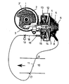
- a conventional and indicated ignition distributor 1 has an interrupter disc 2, on which an interrupter 2 'sits.
- the interrupter disk 2 is set in its rotational position by a pull rod 3, which is actuated by a combined vacuum adjuster 4 known per se.
- the vacuum adjuster 4 consists of a part 5 with a compression spring 6 and a membrane 7 to which the end of the pull rod 3 is attached.
- a hose connection 8 leads to a point 9 in the intake pipe 10 of an internal combustion engine, not shown, which lies in front of a power control element in the form of a throttle valve.
- Part 5 is a so-called early can.
- a second part 12 of the vacuum adjuster 4 consists essentially of an annular membrane 13, which is connected via a connecting part 14 to the membrane 7, a compression spring 15 and a hose connection 16, which is guided to a point 17 in the intake pipe 10, which is after the throttle valve 11 lies.
- the internal combustion engine is provided with a so-called overrun cutoff, by means of which the fuel supply is switched off in the illustrated rest position of the throttle valve 11, provided that the speed of the internal combustion engine is above a so-called re-use speed of e.g. 1100 rpm. This case occurs, for example, in the push mode. If the speed of the internal combustion engine has dropped to the reinstallation speed, the fuel supply is switched on again, the speed of the internal combustion engine then drops to the so-called idling speed of e.g. 900 rpm and maintains this value.
- a so-called overrun cutoff by means of which the fuel supply is switched off in the illustrated rest position of the throttle valve 11, provided that the speed of the internal combustion engine is above a so-called re-use speed of e.g. 1100 rpm. This case occurs, for example, in the push mode. If the speed of the internal combustion engine has dropped to the reinstallation speed, the fuel supply is switched on again, the speed of the internal combustion engine then drops to
- the compression spring 15 is designed so that in the idle position of the throttle valve 11, in which there is a relatively high negative pressure at point 17 at and above the speed at which the internal combustion engine is reinserted, the displacement of the pull rod 3 as a result of the negative pressure acting on the annular diaphragm 13 opposed no resistance. This shifts the ignition timing in the "late" direction. If the speed of the internal combustion engine then drops to the idling speed, the vacuum at point 17 also decreases, for example to half the value. The compression spring 15 gradually comes into effect in accordance with the reduction in the vacuum and cancels the late adjustment of the ignition point.
- a valve 19 can be switched on in the connection 18 of the hose connection 16 to position 17, which valve keeps this connection open until the fuel supply is switched off shortly after it is switched on again.
- the vacuum adjuster 4 i.e. a vacuum adjuster
- the compression spring 15 makes a constant late adjustment of the ignition timing in the rest position of the throttle valve 11.
- the valve 19, which is, for example, a solenoid valve, is actuated in a corresponding manner with a time delay in relation to the switching of the fuel supply.
Applications Claiming Priority (2)
| Application Number | Priority Date | Filing Date | Title |
|---|---|---|---|
| DE19823227777 DE3227777C1 (de) | 1982-07-24 | 1982-07-24 | Vorrichtung zur Spaetverstellung des Zuendzeitpunktes einer Brennkraftmaschine von Kraftfahrzeugen |
| DE3227777 | 1982-07-24 |
Publications (2)
| Publication Number | Publication Date |
|---|---|
| EP0101874A2 true EP0101874A2 (fr) | 1984-03-07 |
| EP0101874A3 EP0101874A3 (fr) | 1986-01-02 |
Family
ID=6169296
Family Applications (1)
| Application Number | Title | Priority Date | Filing Date |
|---|---|---|---|
| EP83107003A Withdrawn EP0101874A3 (fr) | 1982-07-24 | 1983-07-16 | Dispositif de retard à l'allumage d'un moteur à combustion interne |
Country Status (2)
| Country | Link |
|---|---|
| EP (1) | EP0101874A3 (fr) |
| DE (1) | DE3227777C1 (fr) |
Families Citing this family (2)
| Publication number | Priority date | Publication date | Assignee | Title |
|---|---|---|---|---|
| DE3635392C2 (de) * | 1986-10-17 | 1994-06-23 | Bayerische Motoren Werke Ag | Zündzeitpunkt-Spätverstellung für Kraftfahrzeuge |
| DE102015001985A1 (de) | 2015-02-14 | 2016-08-18 | Benjamin-Elias Probst | Doppelkammer Fünftaktmotor Sutur X |
Citations (6)
| Publication number | Priority date | Publication date | Assignee | Title |
|---|---|---|---|---|
| US3452728A (en) * | 1966-10-15 | 1969-07-01 | Ducellier & Cie | Ignition distributor for internal combustion engines |
| GB1181759A (en) * | 1967-12-04 | 1970-02-18 | Ford Motor Co | Fluid Motor Construction |
| DE1930412A1 (de) * | 1969-06-14 | 1971-02-18 | Audi Nsu Auto Union Ag | Verfahren und Vorrichtung zur Verminderung der schaedlichen Abgasbestandteile von Brennkraftmaschinen |
| US3601105A (en) * | 1968-08-12 | 1971-08-24 | Lucas Industries Ltd | Vacuum-operable units for use with ignition distributors |
| US4050423A (en) * | 1974-10-23 | 1977-09-27 | Aisin Seiki Kabushiki Kaisha | Ignition timing adjusting device for internal combustion engines |
| US4259723A (en) * | 1978-05-04 | 1981-03-31 | Nippondenso Co., Ltd. | Method for controlling operations of a combustion engine |
Family Cites Families (2)
| Publication number | Priority date | Publication date | Assignee | Title |
|---|---|---|---|---|
| DE2807499A1 (de) * | 1978-02-22 | 1979-08-23 | Bosch Gmbh Robert | Zuendanlage fuer brennkraftmaschinen |
| DE2916201A1 (de) * | 1979-04-21 | 1980-10-30 | Huels Chemische Werke Ag | Verfahren zur trimerisierung von diisocyanaten |
-
1982
- 1982-07-24 DE DE19823227777 patent/DE3227777C1/de not_active Expired
-
1983
- 1983-07-16 EP EP83107003A patent/EP0101874A3/fr not_active Withdrawn
Patent Citations (6)
| Publication number | Priority date | Publication date | Assignee | Title |
|---|---|---|---|---|
| US3452728A (en) * | 1966-10-15 | 1969-07-01 | Ducellier & Cie | Ignition distributor for internal combustion engines |
| GB1181759A (en) * | 1967-12-04 | 1970-02-18 | Ford Motor Co | Fluid Motor Construction |
| US3601105A (en) * | 1968-08-12 | 1971-08-24 | Lucas Industries Ltd | Vacuum-operable units for use with ignition distributors |
| DE1930412A1 (de) * | 1969-06-14 | 1971-02-18 | Audi Nsu Auto Union Ag | Verfahren und Vorrichtung zur Verminderung der schaedlichen Abgasbestandteile von Brennkraftmaschinen |
| US4050423A (en) * | 1974-10-23 | 1977-09-27 | Aisin Seiki Kabushiki Kaisha | Ignition timing adjusting device for internal combustion engines |
| US4259723A (en) * | 1978-05-04 | 1981-03-31 | Nippondenso Co., Ltd. | Method for controlling operations of a combustion engine |
Also Published As
| Publication number | Publication date |
|---|---|
| EP0101874A3 (fr) | 1986-01-02 |
| DE3227777C1 (de) | 1984-01-05 |
Similar Documents
| Publication | Publication Date | Title |
|---|---|---|
| EP0123731A1 (fr) | Dispositif pour transmettre la position d'un élément de commande | |
| DE2135824A1 (de) | Elektrische kraftstoffeinspritzeinrichtung fuer brennkraftmaschinen mit einer im saugrohr angeordneten drosselklappe und mit einer zur luftmengenmessung dienenden stauklappe | |
| DE2207594B2 (fr) | ||
| DE3137145C2 (fr) | ||
| DE2165432C3 (de) | Zündeinrichtung für eine Kreiskolben-Brennkraftmaschine | |
| DE2342455C3 (de) | Schaltungsanordnung zur elektronischen Drehzahl-Messung bei Brennkraftmaschinen | |
| DE2403278A1 (de) | Vorrichtung zur zufuehrung von beschleunigungskraftstoff waehrend der warmlaufphase einer brennkraftmaschine | |
| EP0101874A2 (fr) | Dispositif de retard à l'allumage d'un moteur à combustion interne | |
| DE1426150A1 (de) | Vorrichtung zum Regeln der Kraftstoffzufuhr bei Verbrennungskraftmaschinen | |
| DE2109373C2 (de) | Doppel-Unterdruckversteller für die Zündzeitpunktverstellung bei Brennkraftmaschinen | |
| DE3014842A1 (de) | Brennkraftmaschine | |
| DE3137161C2 (fr) | ||
| DE3809910C2 (de) | Vorrichtung zur Leistungsbeeinflussung von Brennkraftmaschinen | |
| DE3004199C2 (de) | Vorrichtung zum Absperren der Brennstoffzufuhr im Schiebebetrieb eines Verbrennungsmotors | |
| DE3013942C2 (de) | Vorrichtung zur automatischen Steuerung des Zündzeitpunktes bei einer Brennkraftmaschine mit Turbolader | |
| EP0370218A1 (fr) | Moteur à combustion interne à quatre temps | |
| EP0155273B1 (fr) | Dispositif de dosage du carburant pour un moteur a combustion interne | |
| DE2620181A1 (de) | Vorrichtung zum sicheren schalten von stellgliedern, insbesondere beim betrieb eines kraftfahrzeugs | |
| DE2250756A1 (de) | Brennkraftmaschine mit einer elektrisch gesteuerten benzineinspritzanlage | |
| DE2742119C2 (de) | Vorrichtung zum Steuern eines Vergasers für Verbrennungsmotoren | |
| CH617750A5 (fr) | ||
| DE2636635C2 (de) | Sekundärluftregelanlage zur Auspuffgasreinigung | |
| DE2734145C2 (de) | Steuergerät an Vergasern für Brennkraftmaschinen | |
| DE19530317C1 (de) | Verfahren zur Lasteinstellung einer Brennkraftmaschine | |
| DE2833441C2 (fr) |
Legal Events
| Date | Code | Title | Description |
|---|---|---|---|
| PUAI | Public reference made under article 153(3) epc to a published international application that has entered the european phase |
Free format text: ORIGINAL CODE: 0009012 |
|
| AK | Designated contracting states |
Designated state(s): FR GB IT SE |
|
| PUAL | Search report despatched |
Free format text: ORIGINAL CODE: 0009013 |
|
| AK | Designated contracting states |
Designated state(s): FR GB IT SE |
|
| 17P | Request for examination filed |
Effective date: 19860701 |
|
| STAA | Information on the status of an ep patent application or granted ep patent |
Free format text: STATUS: THE APPLICATION IS DEEMED TO BE WITHDRAWN |
|
| 18D | Application deemed to be withdrawn |
Effective date: 19880201 |
|
| RIN1 | Information on inventor provided before grant (corrected) |
Inventor name: KERN, JOSEF, ING. (GRAD.) |