EP0101874A2 - Device for delaying ignition timing of an internal-combustion engine - Google Patents
Device for delaying ignition timing of an internal-combustion engine Download PDFInfo
- Publication number
- EP0101874A2 EP0101874A2 EP83107003A EP83107003A EP0101874A2 EP 0101874 A2 EP0101874 A2 EP 0101874A2 EP 83107003 A EP83107003 A EP 83107003A EP 83107003 A EP83107003 A EP 83107003A EP 0101874 A2 EP0101874 A2 EP 0101874A2
- Authority
- EP
- European Patent Office
- Prior art keywords
- combustion engine
- ignition timing
- vacuum
- internal combustion
- speed
- Prior art date
- Legal status (The legal status is an assumption and is not a legal conclusion. Google has not performed a legal analysis and makes no representation as to the accuracy of the status listed.)
- Withdrawn
Links
Images
Classifications
-
- F—MECHANICAL ENGINEERING; LIGHTING; HEATING; WEAPONS; BLASTING
- F02—COMBUSTION ENGINES; HOT-GAS OR COMBUSTION-PRODUCT ENGINE PLANTS
- F02P—IGNITION, OTHER THAN COMPRESSION IGNITION, FOR INTERNAL-COMBUSTION ENGINES; TESTING OF IGNITION TIMING IN COMPRESSION-IGNITION ENGINES
- F02P5/00—Advancing or retarding ignition; Control therefor
- F02P5/04—Advancing or retarding ignition; Control therefor automatically, as a function of the working conditions of the engine or vehicle or of the atmospheric conditions
- F02P5/05—Advancing or retarding ignition; Control therefor automatically, as a function of the working conditions of the engine or vehicle or of the atmospheric conditions using mechanical means
- F02P5/10—Advancing or retarding ignition; Control therefor automatically, as a function of the working conditions of the engine or vehicle or of the atmospheric conditions using mechanical means dependent on fluid pressure in engine, e.g. combustion-air pressure
- F02P5/103—Advancing or retarding ignition; Control therefor automatically, as a function of the working conditions of the engine or vehicle or of the atmospheric conditions using mechanical means dependent on fluid pressure in engine, e.g. combustion-air pressure dependent on the combustion-air pressure in engine
Definitions
- the invention relates to a device for the late adjustment of an internal combustion engine of motor vehicles in connection with the fuel cut-off carried out in the push mode at a predetermined speed.
- the aim of the present invention is to provide a device of the type mentioned at the outset which can also be used in conventional ignition systems with a mechanical, inductive or capacitive ignition timing transmitter.
- the invention solves this problem by providing a mechanical U is ntertikversteller turned on for a Zündzeithuigeber to the retard of the ignition timing with the interruption of the fuel supply and for a short time after restarting the supply of fuel.
- the desired retarding of the ignition timing can also be carried out in the invention.
- the structure and mode of operation of the vacuum adjuster used are known in principle.
- a so-called late can is suitable for this purpose, for example, which works together with a so-called early can, which is usually always present in conventional ignition systems.
- the vacuum adjuster provided according to the invention differs in two respects from the usual late can.
- the conventional latex can as a vacuum adjuster.
- the intake pipe of the internal combustion engine which usually serves as a vacuum source
- the vacuum adjuster is ineffective again. This closing can also be done smoothly, which also results in a smooth switching off of the vacuum adjuster and thus a gradual reduction in the ignition timing retard.
- the vacuum adjuster is located at a point behind the power control element connected to the internal combustion engine and its resilience set so that it is effective above and at the reinsertion speed and ineffective at an idle speed below this speed.
- This development is based on the fact that the negative pressure in the intake pipe of the internal combustion engine is greater at the higher reinsertion speed than at idle speed.
- the negative pressure at reinsertion speed can be up to twice the negative pressure at idling speed.
- the desired characteristic can be achieved by appropriately dimensioning the spring force of the spring of the vacuum adjuster, which generally acts as a restoring element.
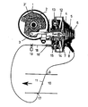
- a conventional and indicated ignition distributor 1 has an interrupter disc 2, on which an interrupter 2 'sits.
- the interrupter disk 2 is set in its rotational position by a pull rod 3, which is actuated by a combined vacuum adjuster 4 known per se.
- the vacuum adjuster 4 consists of a part 5 with a compression spring 6 and a membrane 7 to which the end of the pull rod 3 is attached.
- a hose connection 8 leads to a point 9 in the intake pipe 10 of an internal combustion engine, not shown, which lies in front of a power control element in the form of a throttle valve.
- Part 5 is a so-called early can.
- a second part 12 of the vacuum adjuster 4 consists essentially of an annular membrane 13, which is connected via a connecting part 14 to the membrane 7, a compression spring 15 and a hose connection 16, which is guided to a point 17 in the intake pipe 10, which is after the throttle valve 11 lies.
- the internal combustion engine is provided with a so-called overrun cutoff, by means of which the fuel supply is switched off in the illustrated rest position of the throttle valve 11, provided that the speed of the internal combustion engine is above a so-called re-use speed of e.g. 1100 rpm. This case occurs, for example, in the push mode. If the speed of the internal combustion engine has dropped to the reinstallation speed, the fuel supply is switched on again, the speed of the internal combustion engine then drops to the so-called idling speed of e.g. 900 rpm and maintains this value.
- a so-called overrun cutoff by means of which the fuel supply is switched off in the illustrated rest position of the throttle valve 11, provided that the speed of the internal combustion engine is above a so-called re-use speed of e.g. 1100 rpm. This case occurs, for example, in the push mode. If the speed of the internal combustion engine has dropped to the reinstallation speed, the fuel supply is switched on again, the speed of the internal combustion engine then drops to
- the compression spring 15 is designed so that in the idle position of the throttle valve 11, in which there is a relatively high negative pressure at point 17 at and above the speed at which the internal combustion engine is reinserted, the displacement of the pull rod 3 as a result of the negative pressure acting on the annular diaphragm 13 opposed no resistance. This shifts the ignition timing in the "late" direction. If the speed of the internal combustion engine then drops to the idling speed, the vacuum at point 17 also decreases, for example to half the value. The compression spring 15 gradually comes into effect in accordance with the reduction in the vacuum and cancels the late adjustment of the ignition point.
- a valve 19 can be switched on in the connection 18 of the hose connection 16 to position 17, which valve keeps this connection open until the fuel supply is switched off shortly after it is switched on again.
- the vacuum adjuster 4 i.e. a vacuum adjuster
- the compression spring 15 makes a constant late adjustment of the ignition timing in the rest position of the throttle valve 11.
- the valve 19, which is, for example, a solenoid valve, is actuated in a corresponding manner with a time delay in relation to the switching of the fuel supply.
Abstract
Description
Vorrichtung zur Spätverstellung des Zündzeitpunkts einer Brennkraftmaschine von KraftfahrzeugenDevice for retarding the ignition timing of an internal combustion engine of motor vehicles
Die Erfindung bezieht sich auf eine Vorrichtung zur Spät- verstellung einer Brennkraftmaschine von Kraftfahrzeugen in Zusammenhang mit der im Schiebebetrieb über einer vorgegebenen Drehzahl vorgenommenen Kraftstoffabschaltung.The invention relates to a device for the late adjustment of an internal combustion engine of motor vehicles in connection with the fuel cut-off carried out in the push mode at a predetermined speed.
Es sind zwar bereits derartige Vorrichtungen bekannt, bei denen unmittelbar vor (DE-OS 30 35 245) bzw. nach (DE-OS 28 34 638 entspr. EP-OS 7 998) der Kraftstoffabschaltung der Zündzeitpunkt zurückgenommen wird. Diese bekannten Vorrichtungen arbeiten jedoch im Rahmen von aufwendigen Zündzeitpunkt-Rechnerschaltungen.Devices of this type are already known in which the ignition point is withdrawn immediately before (DE-OS 30 35 245) or after (DE-OS 28 34 638 corresponds to EP-
Ziel der vorliegenden Erfindung ist es, eine Vorrichtung der eingangs genannten Art zu schaffen, die auch bei herkömmlichen Zündanlagen mit einem mechanisch, induktiv oder kapazitiv arbeitenden Zündzeitpunkt-Geber verwendbar ist.The aim of the present invention is to provide a device of the type mentioned at the outset which can also be used in conventional ignition systems with a mechanical, inductive or capacitive ignition timing transmitter.
Die Erfindung löst diese Aufgabe dadurch, daß mit dem Unterbrechen der Kraftstoffzufuhr und kurzzeitig nach dem Wiedereinschalten der Kraftstoffzufuhr ein mechanischer Unterdruckversteller für einen Zündzeitpunktgeber zur Spätverstellung des Zündzeitpunkts eingeschaltet ist.The invention solves this problem by providing a mechanical U is nterdruckversteller turned on for a Zündzeitpunktgeber to the retard of the ignition timing with the interruption of the fuel supply and for a short time after restarting the supply of fuel.
Durch Einwirken auf den Geber selbst läßt sich bei der Erfindung ebenfalls die gewünschte Spätverstellung des Zündzeitpunkts vornehmen. Der Aufbau und die Wirkungsweise des verwendeten Unterdruckverstellers sind im Prinzip bekannt. Es eignet sich hierfür beispielsweise eine sogenannte Spätdose, die zusammen mit einer sogenannten und bei konventionellen Zündanlagen in der Regel stets vorhandenen sogenannten Frühdose zusammenarbeitet. Gegenüber der üblichen Spätdose unterscheidet sich der erfindungsgemäß vorgesehene Unterdruckversteller in zweifacher Hinsicht.By acting on the encoder itself, the desired retarding of the ignition timing can also be carried out in the invention. The structure and mode of operation of the vacuum adjuster used are known in principle. A so-called late can is suitable for this purpose, for example, which works together with a so-called early can, which is usually always present in conventional ignition systems. The vacuum adjuster provided according to the invention differs in two respects from the usual late can.
Zum einen ist er lediglich kurzzeitig und in Verbindung mit dem Unterbrechen der Kraftstoffzufuhr im Schiebebetrieb wirksam. Daraus ergibt sich, daß er zum zweiten im Leerlauf der Brennkraftmaschine üblicherweise nicht wirksam ist. Die übliche Spätdose hingegen ist gerade im Leerlauf und auch im übergangsbereich zwischen Leerlauf- und Wiedereinsetz-Drehzahl wirksam.On the one hand, it is only effective for a short time and in connection with the interruption of the fuel supply in push mode. It follows from this that, secondly, it is usually not effective when the internal combustion engine is idling. The usual late can, however, is particularly effective at idle and also in the transition area between idle and re-use speed.
Zwar ist es gemäß einer Weiterbildung der Erfindung möglich, die übliche Spätdose als Unterdruckversteller zu verwenden. Hierzu ist sie jedoch mit Hilfe eines Ventils mit konstanter Öffnungszeit nach Beendigung der Kraftstoffabschaltung nur vorübergehend mit dem üblicherweise als Unterdruckquelle dienenden Ansaugrohr der Brennkraftmaschine verbunden. Bei Schließen des Ventils ist damit der Unterdruckversteller wieder unwirksam. Dieses Schließen kann zusätzlich gleitend erfolgen, wodurch sich ebenfalls ein gleitendes Ausschalten des Unterdruckverstellers und damit eine allmähliche Reduzierung der Zündzeitpunkt-Spät- verstellung ergibt.According to a further development of the invention, it is possible to use the conventional latex can as a vacuum adjuster. For this purpose, however, it is only temporarily connected to the intake pipe of the internal combustion engine, which usually serves as a vacuum source, with the aid of a valve with a constant opening time after the fuel cutoff has ended. When the valve is closed, the vacuum adjuster is ineffective again. This closing can also be done smoothly, which also results in a smooth switching off of the vacuum adjuster and thus a gradual reduction in the ignition timing retard.
Eine andere Weiterbildung der Erfindung sieht vor, den Aufbau der üblichen Spätdose als Unterdruckversteller zwar im Prinzip zu übernehmen, diesen jedoch so abzuwandeln, daß sich die zeitlich beschränkte Wirksamkeit des Unterdruckverstellers von selbst ergibt. Hierbei wird der Unterdruckversteller an einer Stelle hinter dem Leistungsregelorgan der Brennkraftmaschine angeschlossen und sein Rückstellvermögen so eingestellt, daß er über und bei der Wiedereinsetz-Drehzahl wirksam und bei einer unter dieser Drehzahl liegenden Leerlauf-Drehzahl unwirksam ist. Diese Weiterbildung beruht auf dem Umstand, daß der Unterdruck im Ansaugrohr der Brennkraftmaschine bei der höheren Wiedereinsetz-Drehzahl größer als bei Leerlauf-Drehzahl ist. Je nach Lage der beiden Drehzahlen kann der Unterdruck bei Wiedereinsetz-Drehzahl bis zum zweifachen des Unterdrucks bei Leerlauf-Drehzahl betragen. Durch entsprechende Dimensionierung der Federkraft der in der Regel als Rückstellorgan wirkenden Feder des Unterdruckverstellers läßt sich damit die gewünschte Charakteristik erreichen.Another development of the invention provides that the structure of the conventional late-night box as a vacuum adjuster is in principle adopted, but modified in such a way that the vacuum adjuster's limited effectiveness is self-evident. Here, the vacuum adjuster is located at a point behind the power control element connected to the internal combustion engine and its resilience set so that it is effective above and at the reinsertion speed and ineffective at an idle speed below this speed. This development is based on the fact that the negative pressure in the intake pipe of the internal combustion engine is greater at the higher reinsertion speed than at idle speed. Depending on the position of the two speeds, the negative pressure at reinsertion speed can be up to twice the negative pressure at idling speed. The desired characteristic can be achieved by appropriately dimensioning the spring force of the spring of the vacuum adjuster, which generally acts as a restoring element.
In der Zeichnung ist ein Ausführungsbeispiel der Erfindung dargestellt.In the drawing, an embodiment of the invention is shown.
Ein herkömmlicher und andeutungsweise dargestellter Zündverteiler 1 besitzt eine Unterbrecherscheibe 2, auf der ein Unterbrecher 2' sitzt. Die-Unterbrecherscheibe 2 ist durch eine Zugstange 3 in ihrer Drehlage eingestellt, die durch einen an sich bekannten kombinierten Unterdruckversteller 4 betätigt wird.A conventional and indicated
Der Unterdruckversteller 4 besteht aus einem Teil 5 mit einer Druckfeder 6 und einer Membrane 7,an der das Ende der Zugstange 3 befestigt ist. Ein Schlauchanschluß 8 führt zu einer Stelle 9 im Ansaugrohr 10 einer nicht dargestellten Brennkraftmaschine, die vor einem Leistungsregelorgan in Form einer Drosselklappell liegt. Der Teil 5 stellt eine sogenannte Frühdose dar.The
Ein zweiter Teil 12 des Unterdruckversteller 4 besteht im wesentlichen aus einer Ringmembrane 13, die über ein Verbindungsteil 14 mit der Membrane 7 verbunden ist, einer Druckfeder 15 sowie einem Schlauchanschluß 16, der zu einer Stelle 17 im Ansaugrohr 10 geführt ist, die nach der Drosselklappe 11 liegt.A
Die Brennkraftmaschine ist mit einer sogenannten Schubabschaltung versehen, durch die in der dargestellten Ruhelage der Drosselklappe 11 die Kraftstoffzufuhr abgeschaltet wird, sofern die Drehzahl der Brennkraftmaschine über einer sogenannten Wiedereinsetz-Drehzahl von z.B. 1100 U/min liegt. Dieser Fall tritt beispielsweise im Schiebebetrieb auf. Ist die Drehzahl der Brennkraftmaschine auf die Wiedereinsetz-Drehzahl abgefallen, so wird die Kraftstoffzufuhr wieder eingeschaltet, die Drehzahl der Brennkraftmaschine sinkt ohne äußere Einflüsse dann auf die sogenannten Leerlauf-Drehzahl von z.B. 900 U/min ab und hält diesen Wert bei.The internal combustion engine is provided with a so-called overrun cutoff, by means of which the fuel supply is switched off in the illustrated rest position of the
Um einen bei Wiedereinsetzen der Kraftstoffzufuhr bei Unterschreiten der Wiedereinsetz-Drehzahl normalerweise auftretenden harten Einsatzruck.des Motors zu vermeiden, erfolgt eine vorübergehende Zündungsrücknahme. Hierzu ist die Druckfeder 15 so ausgelegt, daß sie in der Leerlaufstellung der Drosselklappe 11, in der über und bei Wiedereinsetz-Drehzahl der Brennkraftmaschine an der Stelle 17 ein relativ hoher Unterdruck vorliegt, der Verschiebung der Zugstange 3 infolge des auf die Ringmembrane 13 wirkenden Unterdrucks keinen Widerstand entgegensetzt. Der Zündzeitpunkt wird dadurch in Richtung "spät" verschoben. Sinkt die Drehzahl der Brennkraftmaschine dann auf die Leerlauf-Drehzahl ab, verringert sich auch der Unterdruck an der Stelle 17 beispielsweise auf den halben Wert. Die Druckfeder 15 gelangt dabei entsprechend der Verringerung des Unterdrucks allmählich zur Wirkung und hebt die Spät-Verstellung des Zündzeitpunkts wieder auf.In order to avoid the hard operating jolt of the engine that normally occurs when the fuel supply is restored when the reinstallation speed is undershot, the ignition is temporarily withdrawn. For this purpose, the
Gegenüber einem herkömmlichen Unterdruckversteller, dessen Aufbau identisch mit dem Unterdruckversteller 4 ist und bei dem das dem Teil 12 entsprechende Teil als sogenannte Spätdose mit konstanter Spät-Verstellung des Zündzeitpunkts sowohl bei Leerlauf- als auch Wiedereinsetz -Drehzahl dient, läßt sich die beschriebene Funktion durch Vergrößerung der Federkraft der Druckfeder 15 erreichen.Compared to a conventional vacuum adjuster, the construction of which is identical to the
In Fällen, in denen die Leerlauf- und die Wiedereinsetz-Drehzahl sehr nahe beieinander liegen, kann in der Verbindung 18 des Schlauchanschluß 16 zur Stelle 17 ein Ventil 19 eingeschaltet sein, das diese Verbindung bei Abschalten der Kraftstoffzufuhr bis kurze Zeit nach deren Wiedereinschalten offenhält. In diesem Fall ist es möglich, als Unterdruckversteller 4 eine handelsübliche sogenannte Früh-Spät-Dose zu verwenden, d.h. einen Unterdruckversteller, dessen Druckfeder 15 eine konstante Spät-Verstellung des Zündzeitpunkts in der Ruhelage der Drosselklappe 11 vornimmt. Das Ventil 19, bei dem es sich beispielsweise um ein Magnetventil handelt, wird in der entsprechenden Weise zeitverzögert gegenüber der Schaltung der Kraftstoffzufuhr betätigt.In cases where the idle speed and the reinsertion speed are very close to each other, a
Claims (4)
Applications Claiming Priority (2)
| Application Number | Priority Date | Filing Date | Title |
|---|---|---|---|
| DE3227777 | 1982-07-24 | ||
| DE19823227777 DE3227777C1 (en) | 1982-07-24 | 1982-07-24 | Device for late adjustment of the ignition time of an internal combustion engine of motor vehicles |
Publications (2)
| Publication Number | Publication Date |
|---|---|
| EP0101874A2 true EP0101874A2 (en) | 1984-03-07 |
| EP0101874A3 EP0101874A3 (en) | 1986-01-02 |
Family
ID=6169296
Family Applications (1)
| Application Number | Title | Priority Date | Filing Date |
|---|---|---|---|
| EP83107003A Withdrawn EP0101874A3 (en) | 1982-07-24 | 1983-07-16 | Device for delaying ignition timing of an internal-combustion engine |
Country Status (2)
| Country | Link |
|---|---|
| EP (1) | EP0101874A3 (en) |
| DE (1) | DE3227777C1 (en) |
Families Citing this family (2)
| Publication number | Priority date | Publication date | Assignee | Title |
|---|---|---|---|---|
| DE3635392C2 (en) * | 1986-10-17 | 1994-06-23 | Bayerische Motoren Werke Ag | Ignition retard for motor vehicles |
| DE102015001985A1 (en) | 2015-02-14 | 2016-08-18 | Benjamin-Elias Probst | Double chamber five-stroke engine Sutur X |
Citations (6)
| Publication number | Priority date | Publication date | Assignee | Title |
|---|---|---|---|---|
| US3452728A (en) * | 1966-10-15 | 1969-07-01 | Ducellier & Cie | Ignition distributor for internal combustion engines |
| GB1181759A (en) * | 1967-12-04 | 1970-02-18 | Ford Motor Co | Fluid Motor Construction |
| DE1930412A1 (en) * | 1969-06-14 | 1971-02-18 | Audi Nsu Auto Union Ag | Method and device for reducing harmful exhaust gas components from internal combustion engines |
| US3601105A (en) * | 1968-08-12 | 1971-08-24 | Lucas Industries Ltd | Vacuum-operable units for use with ignition distributors |
| US4050423A (en) * | 1974-10-23 | 1977-09-27 | Aisin Seiki Kabushiki Kaisha | Ignition timing adjusting device for internal combustion engines |
| US4259723A (en) * | 1978-05-04 | 1981-03-31 | Nippondenso Co., Ltd. | Method for controlling operations of a combustion engine |
Family Cites Families (2)
| Publication number | Priority date | Publication date | Assignee | Title |
|---|---|---|---|---|
| DE2807499A1 (en) * | 1978-02-22 | 1979-08-23 | Bosch Gmbh Robert | IGNITION SYSTEM FOR COMBUSTION MACHINERY |
| DE2916201A1 (en) * | 1979-04-21 | 1980-10-30 | Huels Chemische Werke Ag | METHOD FOR TRIMERIZING DIISOCYANATES |
-
1982
- 1982-07-24 DE DE19823227777 patent/DE3227777C1/en not_active Expired
-
1983
- 1983-07-16 EP EP83107003A patent/EP0101874A3/en not_active Withdrawn
Patent Citations (6)
| Publication number | Priority date | Publication date | Assignee | Title |
|---|---|---|---|---|
| US3452728A (en) * | 1966-10-15 | 1969-07-01 | Ducellier & Cie | Ignition distributor for internal combustion engines |
| GB1181759A (en) * | 1967-12-04 | 1970-02-18 | Ford Motor Co | Fluid Motor Construction |
| US3601105A (en) * | 1968-08-12 | 1971-08-24 | Lucas Industries Ltd | Vacuum-operable units for use with ignition distributors |
| DE1930412A1 (en) * | 1969-06-14 | 1971-02-18 | Audi Nsu Auto Union Ag | Method and device for reducing harmful exhaust gas components from internal combustion engines |
| US4050423A (en) * | 1974-10-23 | 1977-09-27 | Aisin Seiki Kabushiki Kaisha | Ignition timing adjusting device for internal combustion engines |
| US4259723A (en) * | 1978-05-04 | 1981-03-31 | Nippondenso Co., Ltd. | Method for controlling operations of a combustion engine |
Also Published As
| Publication number | Publication date |
|---|---|
| EP0101874A3 (en) | 1986-01-02 |
| DE3227777C1 (en) | 1984-01-05 |
Similar Documents
| Publication | Publication Date | Title |
|---|---|---|
| EP0123731A1 (en) | Device for transmitting the position of a control element | |
| DE2135824A1 (en) | ELECTRIC FUEL INJECTION DEVICE FOR COMBUSTION MACHINES WITH A THROTTLE FLAP IN THE SUCTION MANIFOLD AND WITH A FLAP FOR MEASURING THE AIR QUANTITY | |
| DE2207594B2 (en) | ||
| DE3137145C2 (en) | ||
| DE2165432C3 (en) | Ignition device for a rotary piston internal combustion engine | |
| DE2342455C3 (en) | Circuit arrangement for electronic speed measurement in internal combustion engines | |
| DE2403278A1 (en) | DEVICE FOR SUPPLYING ACCELERATING FUEL DURING THE WARM-UP PHASE OF A COMBUSTION ENGINE | |
| EP0101874A2 (en) | Device for delaying ignition timing of an internal-combustion engine | |
| DE1426150A1 (en) | Device for regulating the fuel supply in internal combustion engines | |
| DE3014842A1 (en) | INTERNAL COMBUSTION ENGINE | |
| DE3137161C2 (en) | ||
| DE3809910C2 (en) | Device for influencing the performance of internal combustion engines | |
| DE2109373C2 (en) | Double vacuum adjuster for the ignition timing adjustment in internal combustion engines | |
| DE3004199C2 (en) | Device for shutting off the fuel supply in overrun mode of an internal combustion engine | |
| DE3013942C2 (en) | Device for the automatic control of the ignition point in an internal combustion engine with a turbocharger | |
| EP0370218A1 (en) | Four-stroke internal-combustion engine | |
| EP0155273B1 (en) | Fuel metering device for an internal combustion engine | |
| DE2620181A1 (en) | DEVICE FOR SAFE SWITCHING OF ACTUATORS, IN PARTICULAR WHEN OPERATING A MOTOR VEHICLE | |
| DE2250756A1 (en) | COMBUSTION MACHINE WITH AN ELECTRICALLY CONTROLLED GASOLINE INJECTION SYSTEM | |
| DE2742119C2 (en) | Device for controlling a carburetor for internal combustion engines | |
| CH617750A5 (en) | ||
| DE2636635C2 (en) | Secondary air control system for exhaust gas cleaning | |
| DE2734145C2 (en) | Control unit on carburettors for internal combustion engines | |
| DE19530317C1 (en) | Load adjustment for internal combustion engine | |
| DE2833441C2 (en) |
Legal Events
| Date | Code | Title | Description |
|---|---|---|---|
| PUAI | Public reference made under article 153(3) epc to a published international application that has entered the european phase |
Free format text: ORIGINAL CODE: 0009012 |
|
| AK | Designated contracting states |
Designated state(s): FR GB IT SE |
|
| PUAL | Search report despatched |
Free format text: ORIGINAL CODE: 0009013 |
|
| AK | Designated contracting states |
Designated state(s): FR GB IT SE |
|
| 17P | Request for examination filed |
Effective date: 19860701 |
|
| STAA | Information on the status of an ep patent application or granted ep patent |
Free format text: STATUS: THE APPLICATION IS DEEMED TO BE WITHDRAWN |
|
| 18D | Application deemed to be withdrawn |
Effective date: 19880201 |
|
| RIN1 | Information on inventor provided before grant (corrected) |
Inventor name: KERN, JOSEF, ING. (GRAD.) |