EP0099145A1 - Rippenkäfiganschluss - Google Patents
Rippenkäfiganschluss Download PDFInfo
- Publication number
- EP0099145A1 EP0099145A1 EP83200921A EP83200921A EP0099145A1 EP 0099145 A1 EP0099145 A1 EP 0099145A1 EP 83200921 A EP83200921 A EP 83200921A EP 83200921 A EP83200921 A EP 83200921A EP 0099145 A1 EP0099145 A1 EP 0099145A1
- Authority
- EP
- European Patent Office
- Prior art keywords
- rib cage
- spine
- rib
- terminal according
- terminal
- Prior art date
- Legal status (The legal status is an assumption and is not a legal conclusion. Google has not performed a legal analysis and makes no representation as to the accuracy of the status listed.)
- Granted
Links
- 210000000038 chest Anatomy 0.000 title claims abstract description 46
- 230000001154 acute effect Effects 0.000 claims abstract description 4
- 239000002184 metal Substances 0.000 description 4
- 229910052751 metal Inorganic materials 0.000 description 4
- 238000003780 insertion Methods 0.000 description 3
- 230000037431 insertion Effects 0.000 description 3
- 229910000906 Bronze Inorganic materials 0.000 description 2
- 239000010974 bronze Substances 0.000 description 2
- 229910000881 Cu alloy Inorganic materials 0.000 description 1
- 229910000570 Cupronickel Inorganic materials 0.000 description 1
- DMFGNRRURHSENX-UHFFFAOYSA-N beryllium copper Chemical compound [Be].[Cu] DMFGNRRURHSENX-UHFFFAOYSA-N 0.000 description 1
- KUNSUQLRTQLHQQ-UHFFFAOYSA-N copper tin Chemical compound [Cu].[Sn] KUNSUQLRTQLHQQ-UHFFFAOYSA-N 0.000 description 1
- 238000004519 manufacturing process Methods 0.000 description 1
- 238000012986 modification Methods 0.000 description 1
- 230000004048 modification Effects 0.000 description 1
- 229910000679 solder Inorganic materials 0.000 description 1
- 238000010618 wire wrap Methods 0.000 description 1
Images


Classifications
-
- H—ELECTRICITY
- H01—ELECTRIC ELEMENTS
- H01R—ELECTRICALLY-CONDUCTIVE CONNECTIONS; STRUCTURAL ASSOCIATIONS OF A PLURALITY OF MUTUALLY-INSULATED ELECTRICAL CONNECTING ELEMENTS; COUPLING DEVICES; CURRENT COLLECTORS
- H01R13/00—Details of coupling devices of the kinds covered by groups H01R12/70 or H01R24/00 - H01R33/00
- H01R13/02—Contact members
- H01R13/10—Sockets for co-operation with pins or blades
- H01R13/11—Resilient sockets
- H01R13/111—Resilient sockets co-operating with pins having a circular transverse section
-
- H—ELECTRICITY
- H01—ELECTRIC ELEMENTS
- H01R—ELECTRICALLY-CONDUCTIVE CONNECTIONS; STRUCTURAL ASSOCIATIONS OF A PLURALITY OF MUTUALLY-INSULATED ELECTRICAL CONNECTING ELEMENTS; COUPLING DEVICES; CURRENT COLLECTORS
- H01R13/00—Details of coupling devices of the kinds covered by groups H01R12/70 or H01R24/00 - H01R33/00
- H01R13/02—Contact members
- H01R13/10—Sockets for co-operation with pins or blades
- H01R13/11—Resilient sockets
- H01R13/114—Resilient sockets co-operating with pins or blades having a square transverse section
-
- H—ELECTRICITY
- H01—ELECTRIC ELEMENTS
- H01R—ELECTRICALLY-CONDUCTIVE CONNECTIONS; STRUCTURAL ASSOCIATIONS OF A PLURALITY OF MUTUALLY-INSULATED ELECTRICAL CONNECTING ELEMENTS; COUPLING DEVICES; CURRENT COLLECTORS
- H01R13/00—Details of coupling devices of the kinds covered by groups H01R12/70 or H01R24/00 - H01R33/00
- H01R13/02—Contact members
- H01R13/35—Contact members for non-simultaneous co-operation with different types of contact member, e.g. socket co-operating with either round or flat pin
Definitions
- This invention relates to electrical connectors. More particularly, it refers to a rib cage terminal for use in connecting to rounc or square pins.
- My terminal has an electrically conducting rib cage mounted on one end of a spine and another electrically conducting device such as a second rib cage on the other end of tne spine.
- the two rib cages are separated by a mid-portion of the spine.
- the rib cages have at least two pair of ribs in the form of curved cantilevered beams, each beam attached at one end to the spine and spaced apart at its other end from a corresponding oeam.
- Eacn beam is at an acute angle with respect to the center of the spine.
- the diameter of the rib cage is sufficient to receive a round or square pin from another electrical device.
- the spine also has mounting tabs at each end extending in a direction away from the rib cages.
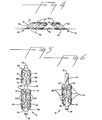
- FIG. 1 there is shown a rib cage terminal 10 mounted in a housing 28.
- a pin 12 is shown ready for insertion into the rib cage terminal 10.
- Ribs 14 in the rib cage 9 form an acute angle with regard to the spine 16 of the terminal 10.
- the bridging mid-portion 11 of the spine 16 separates two sets of rib cages 9.
- Mounting tab 18 assists in maintaining the position of the terminal 10 within the housing 28.
- Slots 19 separate the ribs.
- a rib bridge 20 separates the top of each rib 14.
- the sloped terminal face 30 of the rib 14 receives the terminal pin 12 after the pin has passed through the opening or pin channel 26 in the housing.
- Chamfered edges 24 in the housing 28 maintain easy entry of the pin 12.
- a central opening 22 within the inside space of the rib cage 9 receives the pin 12.
- the pin is of such a diameter as to slightly spread the ribs 14 during insertion.
- the ribs 14 contract after withdrawal of the pin 12.
- each pin 12 is inserted from each end of the terminal 10 so that each pin penetrates into the central opening 22 of each rib cage 9. Since the rib cage 9 on the right hand side has only two of the cantilevered beams or ribs 14, the pin on the right side can be removed with less force than the pin on the left sioe whicn must be removed from a rib cage 9 having three pair of ribs 14. As can be seen in FIGS. 38, 5 and 6, the ribs 14 are curved from the spine 16 in an upward direction and are spaced apart from the corresponding rio 14 coming from the other side of the spine 16.
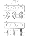
- the terminals of this invention can be made from metal flat strip stock as shown in FIGS. 3A and 3B.
- the carrier strip 32 has pilot holes 33 punched therein.
- a stamping press punches out a design 34.
- a forming press turns the ribs 14 so that the configuration shown in FIG. 38 is achieved.
- the terminal is then removed from the carrier strip and the mounting tabs 18 are formed.
- the terminal is mounted within a housing into a pin channel 26.
- the mounting tab 18 fits into a groove within the-housing and maintains the terminal 10 in a fixed position.
- the metal used to form the terminal of this invention can be any one of phosphor-bronze, beryllium-copper, cupro-nickel, other copper alloys, bronze, or other metal commonly used to manufacture terminals.
- tne spine could also have a pin, a wire wrap tail, a box connector, a pair of double beams, or other suitable electrical contact device. It is preferred to have a rib cage 9 on each side of the spine 16 so that pin contacts can be used at both ends of the terminal.
- FIGS. 9 and 10 show alternative rib cage terminals 10' and 10" respectively.
- FIG. 9 shows a terminal 10' the same as in FIG. 3 except that the rib bridge 20 has been eliminated.
- FIG. 10 shows a terminal 10" which is the same as the one shown in FIG. 6 with the modification that there is no rib bridge 20 as in FIG. 6 and each rib 14" in FIG. 10 is offset with respect to its opposing rib.
Landscapes
- Coupling Device And Connection With Printed Circuit (AREA)
- Dental Preparations (AREA)
- Multi-Conductor Connections (AREA)
- Discharge Heating (AREA)
- Stringed Musical Instruments (AREA)
- Organic Insulating Materials (AREA)
- Brushes (AREA)
- Cable Accessories (AREA)
- Connections Arranged To Contact A Plurality Of Conductors (AREA)
- Casings For Electric Apparatus (AREA)
- Polysaccharides And Polysaccharide Derivatives (AREA)
- Glass Compositions (AREA)
- Connections By Means Of Piercing Elements, Nuts, Or Screws (AREA)
- Connector Housings Or Holding Contact Members (AREA)
- Connections Effected By Soldering, Adhesion, Or Permanent Deformation (AREA)
- Manufacturing Of Electrical Connectors (AREA)
- Details Of Indoor Wiring (AREA)
Priority Applications (1)
| Application Number | Priority Date | Filing Date | Title |
|---|---|---|---|
| AT83200921T ATE27513T1 (de) | 1982-06-21 | 1983-06-20 | Rippenkaefiganschluss. |
Applications Claiming Priority (2)
| Application Number | Priority Date | Filing Date | Title |
|---|---|---|---|
| US390510 | 1982-06-21 | ||
| US06/390,510 US4545638A (en) | 1982-06-21 | 1982-06-21 | Rib cage terminal |
Publications (2)
| Publication Number | Publication Date |
|---|---|
| EP0099145A1 true EP0099145A1 (de) | 1984-01-25 |
| EP0099145B1 EP0099145B1 (de) | 1987-05-27 |
Family
ID=23542756
Family Applications (1)
| Application Number | Title | Priority Date | Filing Date |
|---|---|---|---|
| EP83200921A Expired EP0099145B1 (de) | 1982-06-21 | 1983-06-20 | Rippenkäfiganschluss |
Country Status (13)
| Country | Link |
|---|---|
| US (1) | US4545638A (de) |
| EP (1) | EP0099145B1 (de) |
| JP (3) | JPS598288A (de) |
| KR (1) | KR870001865B1 (de) |
| AT (1) | ATE27513T1 (de) |
| AU (1) | AU556405B2 (de) |
| BR (1) | BR8303202A (de) |
| CA (1) | CA1200864A (de) |
| DE (1) | DE3371839D1 (de) |
| DK (1) | DK161282C (de) |
| ES (2) | ES279045Y (de) |
| MX (1) | MX153193A (de) |
| NO (1) | NO161949C (de) |
Cited By (2)
| Publication number | Priority date | Publication date | Assignee | Title |
|---|---|---|---|---|
| GB2162700A (en) * | 1984-08-01 | 1986-02-05 | Plessey Co Plc | Electrical connectors |
| US6652298B2 (en) | 2000-11-02 | 2003-11-25 | Framatome Connectors International | Connector |
Families Citing this family (19)
| Publication number | Priority date | Publication date | Assignee | Title |
|---|---|---|---|---|
| FR2587848B1 (fr) * | 1985-09-25 | 1988-07-08 | Bonhomme F R | Perfectionnements aux douilles de contact electrique |
| JPH0323666Y2 (de) * | 1985-11-30 | 1991-05-23 | ||
| JPH0332047Y2 (de) * | 1986-01-29 | 1991-07-08 | ||
| US4867691A (en) * | 1987-10-29 | 1989-09-19 | E. I. Du Pont De Nemours And Company | Connector having expansible barrel with a layer of reflowable solder material thereon |
| AU4813790A (en) * | 1988-12-08 | 1990-06-26 | E.I. Du Pont De Nemours And Company | Ribbed terminal having pin lead-in portion thereon |
| US5082462A (en) * | 1988-12-08 | 1992-01-21 | E. I. Du Pont De Nemours And Company | Ribbed terminal having pin lead-in portion thereon |
| US6123587A (en) * | 1996-12-19 | 2000-09-26 | The Whitaker Corporation | Electrical receptacle |
| US6099322A (en) * | 1997-10-31 | 2000-08-08 | The Whitaker Corporation | Electrical receptacle |
| US5934950A (en) * | 1997-12-18 | 1999-08-10 | Ford Motor Company | Electrical contact with multiple points of contact |
| US6017253A (en) * | 1998-05-27 | 2000-01-25 | Framatome Connectors Interlock Inc. | Electrical connector with a tubular contact formed from an array of V-shaped members |
| DE10202637C1 (de) * | 2002-01-24 | 2003-08-14 | Ims Connector Systems Gmbh | Steckverbinder |
| GB0227901D0 (en) * | 2002-11-29 | 2003-01-08 | Tyco Electronics Ltd Uk | Electrical one-piece double-ended receptacle contact and electrical connector comprising such a contact |
| DE102004052712B4 (de) * | 2004-10-30 | 2014-09-25 | Erni Electronics Gmbh | Einteilige, zweischenklige Kontaktfeder für Miniatur-Steckverbindungen |
| US8616926B2 (en) * | 2009-08-17 | 2013-12-31 | Norman R. Byrne | Solid wire terminal |
| DE102010002565B8 (de) * | 2010-03-04 | 2012-03-22 | Tyco Electronics Amp Gmbh | Anschlussvorrichtung für ein Solarmodul |
| JP5632420B2 (ja) * | 2012-05-07 | 2014-11-26 | ヒロセ電機株式会社 | 端子間接続構造 |
| US9528896B2 (en) | 2013-03-15 | 2016-12-27 | Quartzdyne, Inc. | Quartz resonator pressure transducers and methods of operation |
| BR112017018307A2 (pt) | 2015-02-27 | 2018-04-17 | R Byrne Norman | receptáculos de contato elétrico |
| JP2017059389A (ja) * | 2015-09-16 | 2017-03-23 | 株式会社オートネットワーク技術研究所 | 圧着端子付電線、ワイヤハーネス及び圧着端子 |
Citations (7)
| Publication number | Priority date | Publication date | Assignee | Title |
|---|---|---|---|---|
| GB239345A (en) * | 1924-08-16 | 1925-09-10 | Charles Leonard Arnold | Improvements in or relating to socket tubes for electrical connectors, wall sockets and the like |
| FR960968A (de) * | 1950-04-28 | |||
| FR1009831A (fr) * | 1948-06-29 | 1952-06-04 | Prises de courant à corps tubulaire élastique de diamètre variable | |
| DE965506C (de) * | 1952-08-09 | 1957-06-13 | Siemens Ag | Steckkontakthuelse fuer elektrische Steckvorrichtungen |
| FR1319621A (fr) * | 1961-04-14 | 1963-03-01 | Douille fendue à languettes en quinconces pour raccords électriques | |
| GB1153508A (en) * | 1966-12-22 | 1969-05-29 | Amp Inc | Improvements in Female Electrical Connectors |
| AT365003B (de) * | 1979-05-02 | 1981-12-10 | Neutrik Ag | Kontaktbuchse zur aufnahme eines kontaktstiftes fuer elektrische kontakte |
Family Cites Families (20)
| Publication number | Priority date | Publication date | Assignee | Title |
|---|---|---|---|---|
| DE343712C (de) * | 1919-11-25 | 1921-11-07 | Elektromaterial Kommandit Ges | Schraubenfoermig gewundene, federnde Kontakthuelse fuer elektrische Steckvorrichtungen und Kupplungen |
| FR811272A (fr) * | 1936-09-25 | 1937-04-10 | élément de prise de courant | |
| US2499297A (en) * | 1948-07-02 | 1950-02-28 | Buchanan Electrical Prod Corp | Electric connector |
| DE819266C (de) * | 1949-01-01 | 1951-10-31 | Hirschmann Richard Fa | Kontaktstueck fuer Zwischensteckdosen mit zwei seitlichen und einem vorderen Steckeranschluss |
| GB684143A (en) * | 1949-07-22 | 1952-12-10 | Albrecht Jung Ges Mit Beschrae | Improvements in or relating to electrical contacts |
| DE1023107B (de) * | 1952-04-26 | 1958-01-23 | Albrecht Jung G M B H | Kontaktvorrichtung zur Herstellung einer trennbaren elektrischen Verbindung |
| CH357101A (de) * | 1957-04-29 | 1961-09-30 | Werk Signal Sicherungstech Veb | Lösbare Steckkontaktverbindungs-Einrichtung, enthaltend eine Kontaktfederanordnung und ein Kontaktmesser, bei der die Kontaktfederanordnung in einer Federleiste Aufnahme findet |
| CH378967A (de) * | 1960-02-17 | 1964-06-30 | Stin | Löt- und schraubfreie Steckverbindung mit zwei als Steckelemente ausgebildeten elektrischen Leitern |
| NL277202A (de) * | 1961-04-14 | |||
| GB1000223A (en) * | 1961-08-31 | 1965-08-04 | Wilfred Arthur Richards | Improvements in or relating to electrical connector sockets |
| US3183471A (en) * | 1963-02-08 | 1965-05-11 | Thomas & Betts Corp | Electrical terminal and connection |
| DE1465682A1 (de) * | 1964-10-01 | 1969-04-17 | Harting Elektro W | Kontaktbuchse fuer elektrische Steckverbindungen |
| US3409863A (en) * | 1966-10-11 | 1968-11-05 | Deutsch Co Elec Comp | Electrical junction device |
| AT314008B (de) * | 1970-09-25 | 1974-03-11 | Vibro Meter Ag | Kabelstecker |
| SU377930A1 (ru) * | 1971-06-24 | 1973-04-17 | Казанское Конструкторское Бюро Штепсельных Разъемов | Электроконтактная пара |
| DE2224851A1 (de) * | 1972-05-20 | 1973-12-13 | Daut & Rietz Kg | Buchsenleiste mit in ausnehmungen des leistenkoerpers untergebrachten kontaktfedern |
| DE2615820A1 (de) * | 1976-04-10 | 1977-10-13 | Kostal Fa Leopold | Elektrischer steckeraufnahmeteil |
| JPS5856380B2 (ja) * | 1976-07-08 | 1983-12-14 | 日本ゼオン株式会社 | 食品包装用樹脂組成物 |
| DE2708753C3 (de) * | 1977-03-01 | 1979-11-22 | Fa. Leopold Kostal, 5880 Luedenscheid | Elektrische Kontaktbuchse |
| US4445747A (en) * | 1982-07-21 | 1984-05-01 | E. I. Du Pont De Nemours And Company | Rib cage terminal |
-
1982
- 1982-06-21 US US06/390,510 patent/US4545638A/en not_active Expired - Lifetime
-
1983
- 1983-06-17 BR BR8303202A patent/BR8303202A/pt not_active IP Right Cessation
- 1983-06-20 AT AT83200921T patent/ATE27513T1/de not_active IP Right Cessation
- 1983-06-20 DK DK284183A patent/DK161282C/da active
- 1983-06-20 DE DE8383200921T patent/DE3371839D1/de not_active Expired
- 1983-06-20 NO NO832222A patent/NO161949C/no unknown
- 1983-06-20 JP JP58109466A patent/JPS598288A/ja active Pending
- 1983-06-20 MX MX197721A patent/MX153193A/es unknown
- 1983-06-20 ES ES1983279045U patent/ES279045Y/es not_active Expired
- 1983-06-20 AU AU15941/83A patent/AU556405B2/en not_active Ceased
- 1983-06-20 KR KR1019830002762A patent/KR870001865B1/ko not_active IP Right Cessation
- 1983-06-20 EP EP83200921A patent/EP0099145B1/de not_active Expired
- 1983-06-21 CA CA000430809A patent/CA1200864A/en not_active Expired
-
1984
- 1984-03-05 ES ES1984277912U patent/ES277912Y/es not_active Expired
-
1986
- 1986-03-14 JP JP1986036330U patent/JPH0348858Y2/ja not_active Expired
-
1990
- 1990-02-13 JP JP2029774A patent/JPH0329282A/ja active Pending
Patent Citations (7)
| Publication number | Priority date | Publication date | Assignee | Title |
|---|---|---|---|---|
| FR960968A (de) * | 1950-04-28 | |||
| GB239345A (en) * | 1924-08-16 | 1925-09-10 | Charles Leonard Arnold | Improvements in or relating to socket tubes for electrical connectors, wall sockets and the like |
| FR1009831A (fr) * | 1948-06-29 | 1952-06-04 | Prises de courant à corps tubulaire élastique de diamètre variable | |
| DE965506C (de) * | 1952-08-09 | 1957-06-13 | Siemens Ag | Steckkontakthuelse fuer elektrische Steckvorrichtungen |
| FR1319621A (fr) * | 1961-04-14 | 1963-03-01 | Douille fendue à languettes en quinconces pour raccords électriques | |
| GB1153508A (en) * | 1966-12-22 | 1969-05-29 | Amp Inc | Improvements in Female Electrical Connectors |
| AT365003B (de) * | 1979-05-02 | 1981-12-10 | Neutrik Ag | Kontaktbuchse zur aufnahme eines kontaktstiftes fuer elektrische kontakte |
Cited By (2)
| Publication number | Priority date | Publication date | Assignee | Title |
|---|---|---|---|---|
| GB2162700A (en) * | 1984-08-01 | 1986-02-05 | Plessey Co Plc | Electrical connectors |
| US6652298B2 (en) | 2000-11-02 | 2003-11-25 | Framatome Connectors International | Connector |
Also Published As
| Publication number | Publication date |
|---|---|
| ES277912U (es) | 1984-11-01 |
| DK284183D0 (da) | 1983-06-20 |
| EP0099145B1 (de) | 1987-05-27 |
| ES279045Y (es) | 1985-06-01 |
| JPS598288A (ja) | 1984-01-17 |
| BR8303202A (pt) | 1984-01-31 |
| US4545638A (en) | 1985-10-08 |
| KR840005282A (ko) | 1984-11-05 |
| DK284183A (da) | 1983-12-22 |
| AU556405B2 (en) | 1986-10-30 |
| NO161949C (no) | 1989-10-11 |
| JPH0329282A (ja) | 1991-02-07 |
| AU1594183A (en) | 1984-01-05 |
| NO161949B (no) | 1989-07-03 |
| DE3371839D1 (en) | 1987-07-02 |
| ES279045U (es) | 1984-12-01 |
| MX153193A (es) | 1986-08-20 |
| NO832222L (no) | 1983-12-22 |
| ES277912Y (es) | 1985-05-01 |
| DK161282C (da) | 1991-12-30 |
| JPH0348858Y2 (de) | 1991-10-18 |
| JPS61167390U (de) | 1986-10-17 |
| CA1200864A (en) | 1986-02-18 |
| ATE27513T1 (de) | 1987-06-15 |
| KR870001865B1 (ko) | 1987-10-17 |
| DK161282B (da) | 1991-06-17 |
Similar Documents
| Publication | Publication Date | Title |
|---|---|---|
| US4545638A (en) | Rib cage terminal | |
| US4445747A (en) | Rib cage terminal | |
| US4261629A (en) | Slotted plate terminal | |
| US4416504A (en) | Contact with dual cantilevered arms with narrowed, complimentary tip portions | |
| US5007865A (en) | Electrical receptacle terminal | |
| US4743208A (en) | Pin grid array electrical connector | |
| US4838816A (en) | Electrical terminal having a receptacle contact section of low insertion force | |
| US4039239A (en) | Wire slot clip | |
| US4023879A (en) | Adjustable electrical connector with replaceable contact sub-assembly and variable strain relief | |
| EP0279508B1 (de) | Elektrische Anschlussklemme | |
| US4527852A (en) | Multigauge insulation displacement connector and contacts therefor | |
| US5645445A (en) | Wire termination block | |
| EP0191539B1 (de) | Elektrisches Anschlussendstück für Steckverbinder | |
| CA1062791A (en) | Female electrical contact | |
| US5133672A (en) | Insulation displacement terminal | |
| US4052117A (en) | Integrated circuit socket | |
| EP0109297B1 (de) | Elektrische Kontaktorgane und Zusammenbau elektrischer Verbinder | |
| EP0101290B1 (de) | Isolationsversetzender Verbinder für mehrere Stärken und Kontakte dafür | |
| IE49732B1 (en) | Insulation-displacement connector | |
| US4735588A (en) | Spring contact electrical connector assembly having a twist profile | |
| USRE31132E (en) | Electrical connector and insulation-piercing contact member | |
| US4850904A (en) | Connector for telephone cables | |
| US4752247A (en) | Electrical connector fabricated with unitary frame | |
| US3178676A (en) | Pin contact | |
| EP0139786A1 (de) | Einpress-Steckverbinder sowie Isoliergehäuse und Kontakte für diesen |
Legal Events
| Date | Code | Title | Description |
|---|---|---|---|
| PUAI | Public reference made under article 153(3) epc to a published international application that has entered the european phase |
Free format text: ORIGINAL CODE: 0009012 |
|
| AK | Designated contracting states |
Designated state(s): AT BE CH DE FR GB IT LI LU NL SE |
|
| 17P | Request for examination filed |
Effective date: 19840319 |
|
| GRAA | (expected) grant |
Free format text: ORIGINAL CODE: 0009210 |
|
| AK | Designated contracting states |
Kind code of ref document: B1 Designated state(s): AT BE CH DE FR GB IT LI LU NL SE |
|
| REF | Corresponds to: |
Ref document number: 27513 Country of ref document: AT Date of ref document: 19870615 Kind code of ref document: T |
|
| ITF | It: translation for a ep patent filed | ||
| REF | Corresponds to: |
Ref document number: 3371839 Country of ref document: DE Date of ref document: 19870702 |
|
| ET | Fr: translation filed | ||
| PLBE | No opposition filed within time limit |
Free format text: ORIGINAL CODE: 0009261 |
|
| STAA | Information on the status of an ep patent application or granted ep patent |
Free format text: STATUS: NO OPPOSITION FILED WITHIN TIME LIMIT |
|
| 26N | No opposition filed | ||
| ITTA | It: last paid annual fee | ||
| PGFP | Annual fee paid to national office [announced via postgrant information from national office to epo] |
Ref country code: SE Payment date: 19930301 Year of fee payment: 11 |
|
| PGFP | Annual fee paid to national office [announced via postgrant information from national office to epo] |
Ref country code: CH Payment date: 19930302 Year of fee payment: 11 |
|
| PGFP | Annual fee paid to national office [announced via postgrant information from national office to epo] |
Ref country code: BE Payment date: 19930401 Year of fee payment: 11 |
|
| PGFP | Annual fee paid to national office [announced via postgrant information from national office to epo] |
Ref country code: LU Payment date: 19930406 Year of fee payment: 11 |
|
| PGFP | Annual fee paid to national office [announced via postgrant information from national office to epo] |
Ref country code: AT Payment date: 19930413 Year of fee payment: 11 |
|
| PGFP | Annual fee paid to national office [announced via postgrant information from national office to epo] |
Ref country code: NL Payment date: 19930630 Year of fee payment: 11 |
|
| EPTA | Lu: last paid annual fee | ||
| PG25 | Lapsed in a contracting state [announced via postgrant information from national office to epo] |
Ref country code: LU Free format text: LAPSE BECAUSE OF NON-PAYMENT OF DUE FEES Effective date: 19940620 Ref country code: AT Effective date: 19940620 |
|
| PG25 | Lapsed in a contracting state [announced via postgrant information from national office to epo] |
Ref country code: SE Effective date: 19940621 |
|
| PG25 | Lapsed in a contracting state [announced via postgrant information from national office to epo] |
Ref country code: LI Effective date: 19940630 Ref country code: CH Effective date: 19940630 Ref country code: BE Effective date: 19940630 |
|
| BERE | Be: lapsed |
Owner name: E.I. DU PONT DE NEMOURS AND CY Effective date: 19940630 |
|
| PG25 | Lapsed in a contracting state [announced via postgrant information from national office to epo] |
Ref country code: NL Effective date: 19950101 |
|
| EUG | Se: european patent has lapsed |
Ref document number: 83200921.1 Effective date: 19950110 |
|
| NLV4 | Nl: lapsed or anulled due to non-payment of the annual fee | ||
| REG | Reference to a national code |
Ref country code: CH Ref legal event code: PL |
|
| EUG | Se: european patent has lapsed |
Ref document number: 83200921.1 |
|
| REG | Reference to a national code |
Ref country code: GB Ref legal event code: 732E |
|
| REG | Reference to a national code |
Ref country code: FR Ref legal event code: TP |
|
| PGFP | Annual fee paid to national office [announced via postgrant information from national office to epo] |
Ref country code: GB Payment date: 20010502 Year of fee payment: 19 |
|
| PGFP | Annual fee paid to national office [announced via postgrant information from national office to epo] |
Ref country code: FR Payment date: 20010531 Year of fee payment: 19 |
|
| PGFP | Annual fee paid to national office [announced via postgrant information from national office to epo] |
Ref country code: DE Payment date: 20010627 Year of fee payment: 19 |
|
| REG | Reference to a national code |
Ref country code: GB Ref legal event code: IF02 |
|
| PG25 | Lapsed in a contracting state [announced via postgrant information from national office to epo] |
Ref country code: GB Free format text: LAPSE BECAUSE OF NON-PAYMENT OF DUE FEES Effective date: 20020620 |
|
| PG25 | Lapsed in a contracting state [announced via postgrant information from national office to epo] |
Ref country code: DE Free format text: LAPSE BECAUSE OF NON-PAYMENT OF DUE FEES Effective date: 20030101 |
|
| GBPC | Gb: european patent ceased through non-payment of renewal fee |
Effective date: 20020620 |
|
| PG25 | Lapsed in a contracting state [announced via postgrant information from national office to epo] |
Ref country code: FR Free format text: LAPSE BECAUSE OF NON-PAYMENT OF DUE FEES Effective date: 20030228 |
|
| REG | Reference to a national code |
Ref country code: FR Ref legal event code: ST |