EP0095795B2 - Machine perfectionnée pour la réalisation de galeries souterraines - Google Patents
Machine perfectionnée pour la réalisation de galeries souterraines Download PDFInfo
- Publication number
- EP0095795B2 EP0095795B2 EP83200603A EP83200603A EP0095795B2 EP 0095795 B2 EP0095795 B2 EP 0095795B2 EP 83200603 A EP83200603 A EP 83200603A EP 83200603 A EP83200603 A EP 83200603A EP 0095795 B2 EP0095795 B2 EP 0095795B2
- Authority
- EP
- European Patent Office
- Prior art keywords
- cutting drum
- axis
- skirt
- arm
- shield
- Prior art date
- Legal status (The legal status is an assumption and is not a legal conclusion. Google has not performed a legal analysis and makes no representation as to the accuracy of the status listed.)
- Expired - Lifetime
Links
- 238000005520 cutting process Methods 0.000 claims description 56
- 230000008878 coupling Effects 0.000 claims description 15
- 238000010168 coupling process Methods 0.000 claims description 15
- 238000005859 coupling reaction Methods 0.000 claims description 15
- 238000009826 distribution Methods 0.000 claims description 4
- 238000009412 basement excavation Methods 0.000 claims 1
- 239000011796 hollow space material Substances 0.000 claims 1
- 238000003307 slaughter Methods 0.000 description 15
- 241000220223 Fragaria Species 0.000 description 2
- 229910000831 Steel Inorganic materials 0.000 description 2
- 241000897276 Termes Species 0.000 description 2
- 238000010586 diagram Methods 0.000 description 2
- 238000004519 manufacturing process Methods 0.000 description 2
- 230000000149 penetrating effect Effects 0.000 description 2
- 238000003825 pressing Methods 0.000 description 2
- 238000005096 rolling process Methods 0.000 description 2
- 239000002689 soil Substances 0.000 description 2
- 239000010959 steel Substances 0.000 description 2
- 238000010408 sweeping Methods 0.000 description 2
- 241000422252 Cales Species 0.000 description 1
- 235000016623 Fragaria vesca Nutrition 0.000 description 1
- 235000011363 Fragaria x ananassa Nutrition 0.000 description 1
- 241001080024 Telles Species 0.000 description 1
- 240000008042 Zea mays Species 0.000 description 1
- 238000005452 bending Methods 0.000 description 1
- 230000005540 biological transmission Effects 0.000 description 1
- 230000007547 defect Effects 0.000 description 1
- 230000000694 effects Effects 0.000 description 1
- 238000009434 installation Methods 0.000 description 1
- 230000035515 penetration Effects 0.000 description 1
- 238000004513 sizing Methods 0.000 description 1
- 235000021012 strawberries Nutrition 0.000 description 1
- 238000006467 substitution reaction Methods 0.000 description 1
Images


Classifications
-
- E—FIXED CONSTRUCTIONS
- E21—EARTH OR ROCK DRILLING; MINING
- E21D—SHAFTS; TUNNELS; GALLERIES; LARGE UNDERGROUND CHAMBERS
- E21D9/00—Tunnels or galleries, with or without linings; Methods or apparatus for making thereof; Layout of tunnels or galleries
- E21D9/06—Making by using a driving shield, i.e. advanced by pushing means bearing against the already placed lining
- E21D9/0621—Shield advancing devices
-
- E—FIXED CONSTRUCTIONS
- E21—EARTH OR ROCK DRILLING; MINING
- E21D—SHAFTS; TUNNELS; GALLERIES; LARGE UNDERGROUND CHAMBERS
- E21D9/00—Tunnels or galleries, with or without linings; Methods or apparatus for making thereof; Layout of tunnels or galleries
- E21D9/06—Making by using a driving shield, i.e. advanced by pushing means bearing against the already placed lining
- E21D9/08—Making by using a driving shield, i.e. advanced by pushing means bearing against the already placed lining with additional boring or cutting means other than the conventional cutting edge of the shield
- E21D9/0875—Making by using a driving shield, i.e. advanced by pushing means bearing against the already placed lining with additional boring or cutting means other than the conventional cutting edge of the shield with a movable support arm carrying cutting tools for attacking the front face, e.g. a bucket
-
- Y—GENERAL TAGGING OF NEW TECHNOLOGICAL DEVELOPMENTS; GENERAL TAGGING OF CROSS-SECTIONAL TECHNOLOGIES SPANNING OVER SEVERAL SECTIONS OF THE IPC; TECHNICAL SUBJECTS COVERED BY FORMER USPC CROSS-REFERENCE ART COLLECTIONS [XRACs] AND DIGESTS
- Y10—TECHNICAL SUBJECTS COVERED BY FORMER USPC
- Y10T—TECHNICAL SUBJECTS COVERED BY FORMER US CLASSIFICATION
- Y10T403/00—Joints and connections
- Y10T403/70—Interfitted members
- Y10T403/7075—Interfitted members including discrete retainer
- Y10T403/7077—Interfitted members including discrete retainer for telescoping members
Definitions
- the invention relates to an improved machine for producing underground galleries; it aims at a machine making it possible to dig an underground hose and to progressively equip it, as the machine advances, with covering elements supporting the earth such as pipes or segments.
- Such machines are already known which are essentially composed of a hydraulic shield and a slaughter device housed inside the shield.
- the slaughtering device generally constituted by a cutter carried by an arm suspended in the upper part of the shield, makes it possible to dig and split the earth at the front of the shield, this earth being eliminated towards the rear by a conveyor; the hydraulic shield which includes a thrust ring on which a hydraulic thrust system is coupled, allows the shield to advance after completion of the appropriate front earthwork; to generate this progression, the thrust ring is supported on the pipes or segments already installed at the rear of the machine and the hydraulic thrust system hitched at its other end to the shield exerts an effort on the latter advancement (US-A-4,190,294, US-A-4,203,626).
- the curves are very difficult to achieve with this type of machine and require earthworks outside the profile of large sections and therefore a relatively large staff; moreover, the curves produced are with very large radii (the radii of curvature reached being generally greater than approximately 100 times the diameter of the gallery).
- the curves produced are with very large radii (the radii of curvature reached being generally greater than approximately 100 times the diameter of the gallery).
- it sometimes turns out to be impossible to make curves with known machines and professionals are forced to resort to entirely manual earthworks.
- these machines are ill-suited to digging loose ground which tends to "stuff" the cutter with strawberries and absorb very large powers.
- patent EP-A-0 024 445 describes a slaughter device composed of an arm with cascading articulations (of the hydraulic shovel type with horizontal axis); this arm is mounted in a movable frame in translation by means of a rail / gutter system which carries the entire slaughter device in order to allow complete sweeping of the slaughter section.
- a slaughter device is incompatible with the digging of pronounced curves. Indeed, in the pronounced curves, the front case subjected to considerable asymmetric stresses necessarily undergoes an ovalization which results either in jamming effects either by excessive play in the raii / gutter system, which disrupts the operation of the machine.
- the forces that apply to the bucket are reflected by enormous omni-directional stresses on the rail / gutter system given the length of the lever arm of these forces.
- the present invention proposes to remedy the faults of the known machines mentioned above, by providing an improved machine, designed to operate according to the same general principle as the known machines.
- An essential objective of the invention is in particular to authorize the production of much more pronounced curves, without having to perform earthworks outside of the profiles; the invention aims in particular to allow curves to be produced, the radii of which can be easily adjusted to a minimum value of the order of 15 times the diameter of the structure.
- Another objective is to provide a machine adapted to work in any terrain and in particular in soft ground as well in straight lines as in curved lines.
- An objective of the invention is thus to provide a universal machine which can, without difficulty, dig galleries in soils with layers of different natures.
- the floating attachment between the cutting kit and the assembly skirt is adapted so as to allow said kit and said skirt an adjustable relative pivoting up to a value of approximately 4 °.
- the cutting kit comprises, secured to its rear part, an external centering ring in which is fitted an internal centering ring secured to the front of the assembly skirt, said rings being dimensioned so as to be spaced from a functional clearance adapted to allow the aforementioned relative pivoting between the cutting bag and the assembly skirt.
- the front part of the shield (cutting bag) which supports the slaughter device can be oriented in a chosen direction so as to form an adjustable angle relative to the rear part (skirt d 'assembly), which allows the placement of the covering elements.
- the deflection of the cutting kit is obtained by independently controlling the thrust cylinders during shield progression operations: the cylinders located on the outside of the curve to be produced are made to undergo a greater elongation than those located on the inside, the elongation ratios defining the steering angle a.
- the slaughtering device can thus work in an angular direction offset from the previous direction, while allowing, on the one hand, a traditional type of work in line with the profile of the cutting kit, on the other hand , a conventional positioning of the covering elements in the assembly skirt.
- the structure of the felling device allows the arm to easily sweep the entire section of the cutting face (in front of the cutting bag) by the combined play of the 360 ° rotation of the rotating frame and the maneuvers of the arm relative to said rotating frame.
- the tool can be brought to work in all positions; under these conditions, the arm is advantageously equipped with a bucket capable of working in mound or retro, which allows digging without difficulty as well as soft ground than hard ground.
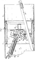
- the improved machine shown by way of example in FIGS. 1, 2, 3, 4 and 5 is intended for the production of underground galleries, of diameter which can vary between 1.80 and 6 meters.
- This machine essentially comprises, on the one hand, a shield made up of two parts, a front cutting kit 1 and a rear assembly skirt 2, on the other hand, a slaughtering device 3 carried by the cutting kit 1.
- the cutting kit 1 is in the form of a cylindrical steel tube provided with a cap 1a at its front part; at its rear part, it is provided with an outer centering ring 4 which is welded to said kit so that its thickness protrudes outside the kit 1, as shown in FIG. 5.
- traction pads such as 5, for example six in number, are welded internally to the rear of the cutting kit 1 and distributed around the periphery thereof, in the vicinity of its junction with the ring 4.
- annular support 6 on which are articulated several hydraulic cylinders such as 7 (for example six in number), distributed over the shielded perimeter .
- the body of each of these jacks is articulated on the support 6 by a conventional yoke.
- assembly skirt 2 is in the form of a cylindrical steel tube, the diameter of which is slightly larger than that of the kit 1 is of the order of that of the outer ring 4 welded to the back of said kit.
- an internal centering ring 3 is welded, the thickness of which protrudes inside said skirt as shown in FIG. 5.
- the ring 8 is fitted into the ring 4, with a functional play between them, adapted to allow a relative pivoting of the cutting kit with respect to the assembly skirt around any axis orthogonal to the axis of these elements.
- the rings 4 and 8 which overlap over a variable longitudinal distance as a function of the relative position of the skirt and the case, provide guiding and relative centering of these elements, avoiding any risk of transverse shift.
- each coupling lug 9 is provided with 'a light 9a, of longitudinal dimension much greater than that of a traction pad 5 and of transverse dimension slightly greater than that of the latter.
- Each of the studs 5 penetrates into a lumen 9a of a tab, so that all of these members constitute a floating attachment subjecting the skirt 2 and the kit 1, d to each other with a determined clearance.
- the skirt 2 guides a thrust ring 10 which is slidably mounted therein.
- a thrust ring 10 which is slidably mounted therein.
- On this ring are coupled, in a conventional manner in themselves, the movable rods of the hydraulic cylinders 7.
- These cylinders are equipped with a hydraulic distribution system allowing them to be supplied and to be controlled independently so as to be able to individually adjust their elongation and adjust thus the relative angular position of the kit 1 relative to the skirt 2.
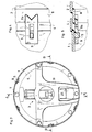
- the slaughtering device 3 carried by the sharp kit 1 comprises a frame 11 having three tripod-shaped extensions, by which it is fixed inside the cutting kit 1, towards the rear portion thereof.
- This frame forms around the axis of the kit a substantially vertical platform 11a, said frame and its platform being hollowed out in the central region of your kit in order to delimit a hollow central volume.
- a rotating frame 12 is mounted at the front of the frame 11 on the vertical platform 11a by means of a crown of bearings of known type, (symbolized at 13 in Figures 1 and 2); this crown of horizontal axis coinciding with the axis of the kit can be of the crossed roller type, its external cage being secured to the platform 11a and its internal cage to the chassis 12.
- the latter has teeth 14 engaged with a pinion 15 which is articulated on the platform 11a and driven in rotation by a hydraulic motor 16 carried at the rear by said platform 11a.
- the rotating frame 12 can thus be rotated 360 ° about a horizontal axis substantially coinciding with the axis of the sharp case.
- a felling arm 18 On this rotating chassis is articulated a felling arm 18, by an axis 17 parallel to the plane of the platform 11 a and located in the vicinity thereof, this articulation axis being eccentric relative to the fictitious center of the platform.
- the felling arm 18 has a rear extension 18a which is housed in the hollow part of the frame 11.
- the movable rod of an actuating cylinder 20 is coupled by an axis 19.
- This cylinder is tilted back as shown in Figure 1 and its body is coupled to a front extension 12a of the rotating frame, at a coupling point 21 located opposite the articulation point 17 of the arm, relative to the axis of the sharp case.
- the articulation point 17 of the arm and the coupling points 19 and 21 of the maneuvering cylinder are thus arranged in a triangle and the arrangement described above of these elements makes it possible both to guarantee good efficiency of the maneuvering cylinder which that is the position of the arm 18 and considerably reduce the space requirement at the front of the platform so as to clear the work area and allow the entire surface of this area to be swept by the arm (despite the division of the shield into two parts, which conditions a significant reduction in the longitudinal dimension of the cutting bag in which the slaughter device is housed).
- the felling arm 18 is advantageously telescopic and comprises two members 18b, 18c mounted to slide relative to one another and a hydraulic cylinder 22 located inside the latter and coupled to them in order to move the member 18b relative to the member 18c in the direction of a retraction or a longitudinal extension.
- the member 18b is equipped at its end with a bucket 23 which is associated with conventional hydraulic maneuvering means, comprising a hydraulic cylinder 24 and transmission rods 25, in order to allow the bucket to be disposed both in position butte only in retro position.
- conventional hydraulic maneuvering means comprising a hydraulic cylinder 24 and transmission rods 25, in order to allow the bucket to be disposed both in position butte only in retro position.
- the various cylinders integral with the rotary chassis 12 (cylinders 20, 22 and 24) are supplied with pressurized oil by a hydraulic rotary joint of the conventional type 26.
- the above-described felling device is capable of effectively digging both loose and harder soils; by the play of the sweeping of the arm and the 360 ° rotation, the bucket can be brought to work indifferently in hillock or in retro, the telescopic nature of the arm allowing a good penetration of the bucket forward.
- Such a slaughter device is adapted to the structure in two distinct parts of the shield and is free from the defects of conventional strawberry devices.
- Figures 6 to 10 illustrate the operation of the machine to produce a curved gallery.
- the machine is assumed in the configuration of FIG. 6.
- the axis X of the cutting kit 1 forms an angle a with the axis Y of the assembly skirt 2, this angle being a function of the curvature of the gallery to achieve.
- the jacks 7 are in the retracted state, those situated outside the curve having greater elongations adapted to the variable distances which separate the coupling points of the various jacks on the front support 6 and on the sliding ring 10 The latter is in its most forward position, pressing against the last coverings which have been put in place in the skirt (segments V).
- kit 1 and skirt 2 are in the position shown diagrammatically in FIG. 7. Shims of different lengths, as shown diagrammatically in broken lines at 27, can be put in place to block the skirt and the sharp kit in the appropriate angular configuration, defined by the differential elongation of the cylinders 7.
- These removable wedges can in particular be manually placed against the traction studs 5 in the slots of the coupling lugs 9. The set of wedges thus put in place allows, during the shield's progression movements, to keep precisely the value of the angle a between the X and Y axes of the case and the skirt.
- the jacks 7 are operated independently in the direction of extension to move the shield forward. (figure 8). This movement is obtained by pressing the pushing ring 10 on the segments V which keep this ring stationary: under the push of the jacks 7, the cutting bag 1 is therefore caused to slide forward in the new length hollowed out and the assembly skirt 2 follows, the progression movement being transmitted to it by the traction pads 5 engaged with the lugs 9 as well as by the jacks 7 which link the cutting kit and the assembly skirt.
- the jacks 7 are retracted by maneuvering them independently so as to preserve their differential elongation (FIG. 9): the sliding ring is then brought back towards the front of the assembly skirt 2.
- Such a machine in which the cutting kit 1 and the assembly skirt 2 are capable of forming an angle reaching up to 4 ° makes it possible without difficulty to produce treats having curvatures reaching up to 15 times their diameter: three people are enough to serve it and the average progress can be around 5 meters per 8 hour shift.
Landscapes
- Engineering & Computer Science (AREA)
- Mining & Mineral Resources (AREA)
- Environmental & Geological Engineering (AREA)
- Life Sciences & Earth Sciences (AREA)
- General Life Sciences & Earth Sciences (AREA)
- Geochemistry & Mineralogy (AREA)
- Geology (AREA)
- Excavating Of Shafts Or Tunnels (AREA)
- Control Of Electric Motors In General (AREA)
- Separation By Low-Temperature Treatments (AREA)
Priority Applications (1)
| Application Number | Priority Date | Filing Date | Title |
|---|---|---|---|
| AT83200603T ATE14777T1 (de) | 1982-06-02 | 1983-04-28 | Maschine zum unterirdischen streckenvortrieb. |
Applications Claiming Priority (2)
| Application Number | Priority Date | Filing Date | Title |
|---|---|---|---|
| FR8209835 | 1982-06-02 | ||
| FR8209835A FR2528108A1 (fr) | 1982-06-02 | 1982-06-02 | Machine perfectionnee a bouclier pour le creusement de galeries souterraines |
Publications (3)
| Publication Number | Publication Date |
|---|---|
| EP0095795A1 EP0095795A1 (fr) | 1983-12-07 |
| EP0095795B1 EP0095795B1 (fr) | 1985-08-07 |
| EP0095795B2 true EP0095795B2 (fr) | 1991-07-24 |
Family
ID=9274683
Family Applications (1)
| Application Number | Title | Priority Date | Filing Date |
|---|---|---|---|
| EP83200603A Expired - Lifetime EP0095795B2 (fr) | 1982-06-02 | 1983-04-28 | Machine perfectionnée pour la réalisation de galeries souterraines |
Country Status (5)
| Country | Link |
|---|---|
| US (1) | US4508390A (OSRAM) |
| EP (1) | EP0095795B2 (OSRAM) |
| AT (1) | ATE14777T1 (OSRAM) |
| DE (1) | DE3360516D1 (OSRAM) |
| FR (1) | FR2528108A1 (OSRAM) |
Families Citing this family (14)
| Publication number | Priority date | Publication date | Assignee | Title |
|---|---|---|---|---|
| DE3342903C2 (de) * | 1983-11-26 | 1985-10-10 | Hochtief Ag Vorm. Gebr. Helfmann, 4300 Essen | Entkoppelungseinrichtung zum Entkoppeln der Bewegung des Vorlaufschildes und der Stirnschalung für eine Vortriebsmaschine |
| JPS61172993A (ja) * | 1985-01-29 | 1986-08-04 | 株式会社 イセキ開発工機 | シ−ルドトンネル掘進装置 |
| FR2589516B1 (fr) * | 1985-11-06 | 1988-05-20 | Bessac Creusement Soutenement | Procede et machine a bouclier pour le creusement de galeries souterraines, notamment dans des sols aquiferes a faible cohesion |
| JPH086551B2 (ja) * | 1989-07-19 | 1996-01-24 | 株式会社イセキ開発工機 | シールド型トンネル機械の方向修正装置 |
| DE3732261A1 (de) * | 1987-09-25 | 1989-04-06 | Bilfinger Berger Bau | Verfahren zur herstellung eines tunnels und schildvortriebsmaschine zur durchfuehrung des verfahrens |
| US4915453A (en) * | 1988-04-18 | 1990-04-10 | Fikse Tyman H | Floating shoe tunnel boring machine and boring process |
| IT1241160B (it) * | 1990-04-02 | 1993-12-29 | Carlo Grandori | Fresa a doppio scudo telescopico perfezionata. |
| US5221160A (en) * | 1990-04-26 | 1993-06-22 | Shimizuo Construction Co. | Subterranean connecting method for construction of shield tunnel and connecting apparatus therefor |
| FR2851009B1 (fr) * | 2003-02-10 | 2005-04-01 | Andre Boniface | Tunnelier a percussion apte a la realisation de tunnels a geometrie polygonale dans des sols tres durs |
| US7651170B2 (en) * | 2003-07-18 | 2010-01-26 | Rodney John Davies | Bore head for microbore operation |
| JP6249519B2 (ja) * | 2013-11-27 | 2017-12-20 | 株式会社奥村組 | シールド掘進機およびシールド掘進方法 |
| JP6425057B2 (ja) * | 2014-03-10 | 2018-11-21 | 清水建設株式会社 | 中折れ型トンネル掘削機の制御方法 |
| JP6498624B2 (ja) * | 2016-03-18 | 2019-04-10 | 公益財団法人鉄道総合技術研究所 | 掘削工法模擬装置 |
| JP6573142B2 (ja) * | 2018-07-24 | 2019-09-11 | 清水建設株式会社 | 中折れ型トンネル掘削機の制御方法 |
Family Cites Families (14)
| Publication number | Priority date | Publication date | Assignee | Title |
|---|---|---|---|---|
| FR1388527A (fr) * | 1964-04-15 | 1965-02-05 | Nii Osnovany I Podzemnikh Soor | Appareil pour le percement de tunnels |
| US3556599A (en) * | 1968-12-10 | 1971-01-19 | Tyman H Fikse | Method of tunneling and tunneling shield with a drag loader |
| DE2240967B2 (de) * | 1972-08-21 | 1976-06-10 | Weiss, Benedikt, 4200 Oberhausen | Verfahren und vorrichtung zum kurvenfoermigen vortrieb von stollen oder tunneln aus vorgefertigten betonrohren |
| DE2339702B2 (de) * | 1973-08-06 | 1975-07-10 | Gerhard Dipl.-Ing. 2090 Winsen Paproth | Vortriebsschild zum Auffahren röhrenförmiger unterirdischer Bauwerke mit Nennweiten unter 4 m |
| US3919851A (en) * | 1974-06-17 | 1975-11-18 | M & P Pipe Jacking Corp | Apparatus for the excavation and lining of subterranean tunnels |
| US4027903A (en) * | 1975-02-06 | 1977-06-07 | E. I. Du Pont De Nemours And Company | Water-degradable coupling member |
| US3966256A (en) * | 1975-04-11 | 1976-06-29 | The Robbins Company | Tunneling equipment |
| DE2545041A1 (de) * | 1975-10-08 | 1977-04-21 | Peiner Masch Schrauben | Vorrichtung zum lenken eines tunnelrohres |
| DE2621391A1 (de) * | 1976-05-14 | 1977-11-24 | Gewerk Eisenhuette Westfalia | Presstation, insbesondere zwischenpresstation, fuer einen rohrvorpressbetrieb |
| DE2736398C2 (de) * | 1977-08-12 | 1985-11-21 | Gewerkschaft Eisenhütte Westfalia, 4670 Lünen | Steuervorrichtung für einen Messerschild |
| DE2741637A1 (de) * | 1977-09-15 | 1979-03-22 | Goeppner Kaiserslautern Eisen | Vorrichtung zum vortrieb von tunnel- und stollenroehren |
| US4190294A (en) * | 1978-08-17 | 1980-02-26 | The Robbins Company | Excavator for use in a tunneling shield |
| US4203626A (en) * | 1979-02-21 | 1980-05-20 | Zokor Corporation | Articulated boom-dipper-bucket assembly for a tunnel boring machine |
| DE2952744C2 (de) * | 1979-12-29 | 1985-01-10 | Bade & Theelen Gmbh, 3160 Lehrte | In der Richtung lenkbarer Schildmantel einer Vortriebsmaschine |
-
1982
- 1982-06-02 FR FR8209835A patent/FR2528108A1/fr active Granted
-
1983
- 1983-04-28 AT AT83200603T patent/ATE14777T1/de active
- 1983-04-28 DE DE8383200603T patent/DE3360516D1/de not_active Expired
- 1983-04-28 EP EP83200603A patent/EP0095795B2/fr not_active Expired - Lifetime
- 1983-06-01 US US06/500,413 patent/US4508390A/en not_active Expired - Lifetime
Also Published As
| Publication number | Publication date |
|---|---|
| EP0095795B1 (fr) | 1985-08-07 |
| FR2528108B1 (OSRAM) | 1985-03-08 |
| ATE14777T1 (de) | 1985-08-15 |
| US4508390A (en) | 1985-04-02 |
| EP0095795A1 (fr) | 1983-12-07 |
| FR2528108A1 (fr) | 1983-12-09 |
| DE3360516D1 (en) | 1985-09-12 |
Similar Documents
| Publication | Publication Date | Title |
|---|---|---|
| EP0095795B2 (fr) | Machine perfectionnée pour la réalisation de galeries souterraines | |
| EP0017593B1 (fr) | Engin pour le curage des étangs, marais ou canaux | |
| FR2595107A1 (fr) | Vehicule de type pelleteuse a pivotement complet a rayon reduit pour faciliter les operations dans un site resserre | |
| EP0212316B1 (fr) | Colonne de forage pour forage à déviations, procédé d'utilisation de cette colonne et dispositif déviateur utilisé dans cette colonne | |
| EP0021987B1 (fr) | Machine pour le creusement des galeries souterraines | |
| FR3041024A1 (fr) | Machine de forage munie d'un dispositif d'ancrage permettant un deplacement horizontal du module de forage en position ancree | |
| FR2493370A1 (fr) | Bras articule pour engin d'excavation | |
| EP3241985A1 (fr) | Tunnelier | |
| EP1632638B1 (fr) | Foreuse hydraulique pour travaux en espace réduit | |
| FR2466604A1 (fr) | Machine de forage pour realiser des trous dans le sol | |
| FR2624197A1 (fr) | Procede et dispositif pour nettoyer une tariere, et machine de forage par tariere | |
| FR3050758B1 (fr) | Tunnelier | |
| FR2781118A1 (fr) | Equipement d'ensileuse | |
| EP0631032B1 (fr) | Tunnelier à creusement frontal pleine section | |
| FR2512102A1 (fr) | Cylindre de coupe comprenant un dispositif de pulverisation | |
| EP2206876B1 (fr) | Tête de forage pour machine de forage | |
| FR2506830A1 (fr) | Tariere pendulaire | |
| FR2539157A1 (fr) | Trancheuse a fleche | |
| FR2461806A1 (fr) | Machine de creusement comportant un bras muni d'un outil d'abattage et orientable | |
| EP0696673B1 (fr) | Machine de havage pour le prédécoupage de la voûte d'une galerie | |
| FR2624899A1 (fr) | Machine pour le creusage de rigoles sur le bord des routes, pour l'evacuation de l'eau | |
| SU1263765A1 (ru) | Рабочий орган многоковшового траншейного экскаватора | |
| FR2478190A1 (fr) | Materiel pour l'execution d'un puits, comprenant une plate-forme de travail pour effectuer des operations de percements | |
| EP3012219A1 (fr) | Dispositif de terrassement adaptable sur le tablier d'un chariot telescopique | |
| EP2112277A2 (fr) | Engin de terrassement et godet de chargement pour un tel engin de terrassement |
Legal Events
| Date | Code | Title | Description |
|---|---|---|---|
| PUAI | Public reference made under article 153(3) epc to a published international application that has entered the european phase |
Free format text: ORIGINAL CODE: 0009012 |
|
| AK | Designated contracting states |
Designated state(s): AT BE CH DE GB IT LI LU NL SE |
|
| 17P | Request for examination filed |
Effective date: 19840118 |
|
| ITF | It: translation for a ep patent filed | ||
| GRAA | (expected) grant |
Free format text: ORIGINAL CODE: 0009210 |
|
| AK | Designated contracting states |
Designated state(s): AT BE CH DE GB IT LI LU NL SE |
|
| PG25 | Lapsed in a contracting state [announced via postgrant information from national office to epo] |
Ref country code: NL Effective date: 19850807 Ref country code: AT Effective date: 19850807 |
|
| REF | Corresponds to: |
Ref document number: 14777 Country of ref document: AT Date of ref document: 19850815 Kind code of ref document: T |
|
| PG25 | Lapsed in a contracting state [announced via postgrant information from national office to epo] |
Ref country code: SE Effective date: 19850830 |
|
| REF | Corresponds to: |
Ref document number: 3360516 Country of ref document: DE Date of ref document: 19850912 |
|
| NLV1 | Nl: lapsed or annulled due to failure to fulfill the requirements of art. 29p and 29m of the patents act | ||
| PG25 | Lapsed in a contracting state [announced via postgrant information from national office to epo] |
Ref country code: LU Free format text: LAPSE BECAUSE OF NON-PAYMENT OF DUE FEES Effective date: 19860430 |
|
| PLBI | Opposition filed |
Free format text: ORIGINAL CODE: 0009260 |
|
| 26 | Opposition filed |
Opponent name: GEWERKSCHAFT EISENHUETTE WESTFALIAGMBH Effective date: 19860507 |
|
| PG25 | Lapsed in a contracting state [announced via postgrant information from national office to epo] |
Ref country code: LI Effective date: 19870430 Ref country code: CH Effective date: 19870430 |
|
| GBPC | Gb: european patent ceased through non-payment of renewal fee | ||
| REG | Reference to a national code |
Ref country code: CH Ref legal event code: PL |
|
| PLAB | Opposition data, opponent's data or that of the opponent's representative modified |
Free format text: ORIGINAL CODE: 0009299OPPO |
|
| PG25 | Lapsed in a contracting state [announced via postgrant information from national office to epo] |
Ref country code: GB Effective date: 19881122 |
|
| R26 | Opposition filed (corrected) |
Opponent name: GEWERKSCHAFT EISENHUETTE WESTFALIA GMBH Effective date: 19860507 |
|
| PUAH | Patent maintained in amended form |
Free format text: ORIGINAL CODE: 0009272 |
|
| STAA | Information on the status of an ep patent application or granted ep patent |
Free format text: STATUS: PATENT MAINTAINED AS AMENDED |
|
| 27A | Patent maintained in amended form |
Effective date: 19910724 |
|
| AK | Designated contracting states |
Kind code of ref document: B2 Designated state(s): AT BE CH DE GB IT LI LU NL SE |
|
| APAC | Appeal dossier modified |
Free format text: ORIGINAL CODE: EPIDOS NOAPO |
|
| APAC | Appeal dossier modified |
Free format text: ORIGINAL CODE: EPIDOS NOAPO |
|
| PGFP | Annual fee paid to national office [announced via postgrant information from national office to epo] |
Ref country code: BE Payment date: 20020524 Year of fee payment: 20 |
|
| PGFP | Annual fee paid to national office [announced via postgrant information from national office to epo] |
Ref country code: DE Payment date: 20020529 Year of fee payment: 20 |
|
| BE20 | Be: patent expired |
Owner name: *FONCAGES ET FORAGES BESSAC S.A. Effective date: 20030428 |
|
| APAH | Appeal reference modified |
Free format text: ORIGINAL CODE: EPIDOSCREFNO |