EP0095795B1 - Machine perfectionnée pour la réalisation de galeries souterraines - Google Patents
Machine perfectionnée pour la réalisation de galeries souterraines Download PDFInfo
- Publication number
- EP0095795B1 EP0095795B1 EP83200603A EP83200603A EP0095795B1 EP 0095795 B1 EP0095795 B1 EP 0095795B1 EP 83200603 A EP83200603 A EP 83200603A EP 83200603 A EP83200603 A EP 83200603A EP 0095795 B1 EP0095795 B1 EP 0095795B1
- Authority
- EP
- European Patent Office
- Prior art keywords
- pipe
- skirt
- machine according
- drive
- shield
- Prior art date
- Legal status (The legal status is an assumption and is not a legal conclusion. Google has not performed a legal analysis and makes no representation as to the accuracy of the status listed.)
- Expired
Links
- 230000008878 coupling Effects 0.000 claims description 14
- 238000010168 coupling process Methods 0.000 claims description 14
- 238000005859 coupling reaction Methods 0.000 claims description 14
- 230000000149 penetrating effect Effects 0.000 claims description 2
- 239000011796 hollow space material Substances 0.000 claims 2
- 238000005520 cutting process Methods 0.000 description 32
- 238000003307 slaughter Methods 0.000 description 11
- 239000002689 soil Substances 0.000 description 3
- 241000220223 Fragaria Species 0.000 description 2
- 229910000831 Steel Inorganic materials 0.000 description 2
- 230000007547 defect Effects 0.000 description 2
- 238000010586 diagram Methods 0.000 description 2
- 238000004519 manufacturing process Methods 0.000 description 2
- 230000035515 penetration Effects 0.000 description 2
- 238000003825 pressing Methods 0.000 description 2
- 238000005096 rolling process Methods 0.000 description 2
- 239000010959 steel Substances 0.000 description 2
- 235000016623 Fragaria vesca Nutrition 0.000 description 1
- 235000011363 Fragaria x ananassa Nutrition 0.000 description 1
- 240000008042 Zea mays Species 0.000 description 1
- 230000005540 biological transmission Effects 0.000 description 1
- 239000011248 coating agent Substances 0.000 description 1
- 238000000576 coating method Methods 0.000 description 1
- 238000009826 distribution Methods 0.000 description 1
- 238000009434 installation Methods 0.000 description 1
- 235000021012 strawberries Nutrition 0.000 description 1
- 238000010408 sweeping Methods 0.000 description 1
Images


Classifications
-
- E—FIXED CONSTRUCTIONS
- E21—EARTH OR ROCK DRILLING; MINING
- E21D—SHAFTS; TUNNELS; GALLERIES; LARGE UNDERGROUND CHAMBERS
- E21D9/00—Tunnels or galleries, with or without linings; Methods or apparatus for making thereof; Layout of tunnels or galleries
- E21D9/06—Making by using a driving shield, i.e. advanced by pushing means bearing against the already placed lining
- E21D9/0621—Shield advancing devices
-
- E—FIXED CONSTRUCTIONS
- E21—EARTH OR ROCK DRILLING; MINING
- E21D—SHAFTS; TUNNELS; GALLERIES; LARGE UNDERGROUND CHAMBERS
- E21D9/00—Tunnels or galleries, with or without linings; Methods or apparatus for making thereof; Layout of tunnels or galleries
- E21D9/06—Making by using a driving shield, i.e. advanced by pushing means bearing against the already placed lining
- E21D9/08—Making by using a driving shield, i.e. advanced by pushing means bearing against the already placed lining with additional boring or cutting means other than the conventional cutting edge of the shield
- E21D9/0875—Making by using a driving shield, i.e. advanced by pushing means bearing against the already placed lining with additional boring or cutting means other than the conventional cutting edge of the shield with a movable support arm carrying cutting tools for attacking the front face, e.g. a bucket
-
- Y—GENERAL TAGGING OF NEW TECHNOLOGICAL DEVELOPMENTS; GENERAL TAGGING OF CROSS-SECTIONAL TECHNOLOGIES SPANNING OVER SEVERAL SECTIONS OF THE IPC; TECHNICAL SUBJECTS COVERED BY FORMER USPC CROSS-REFERENCE ART COLLECTIONS [XRACs] AND DIGESTS
- Y10—TECHNICAL SUBJECTS COVERED BY FORMER USPC
- Y10T—TECHNICAL SUBJECTS COVERED BY FORMER US CLASSIFICATION
- Y10T403/00—Joints and connections
- Y10T403/70—Interfitted members
- Y10T403/7075—Interfitted members including discrete retainer
- Y10T403/7077—Interfitted members including discrete retainer for telescoping members
Definitions
- the invention relates to an improved machine for producing underground galleries; it aims at a machine making it possible to dig an underground hose and to progressively equip it, as the machine advances, with covering elements supporting the earth such as pipes or segments.
- Such machines are already known which are essentially composed of a hydraulic shield and a slaughter device housed inside the shield.
- the slaughtering device generally constituted by a cutter carried by an arm suspended in the upper part of the shield, makes it possible to dig and split the earth at the front of the shield, this earth being eliminated towards the rear by a conveyor; the hydraulic shield which includes a thrust ring on which a hydraulic thrust system is coupled, allows the shield to advance after completion of the appropriate front earthwork; to generate this progression, the thrust ring is supported on the pipes or segments already installed at the rear of the machine and the hydraulic thrust system hitched at its other end to the shield exerts an effort on the latter advancement (US-A-4,190,294, US-A-4,203,626).
- the curves are very difficult to achieve with this type of machine and require earthworks outside the profile of large sections and therefore a relatively large staff; moreover, the curves produced are with very large radii (the radii of curvature reached being generally greater than approximately 100 times the diameter of the gallery).
- the curves produced are with very large radii (the radii of curvature reached being generally greater than approximately 100 times the diameter of the gallery).
- it sometimes turns out to be impossible to make curves with known machines and professionals are forced to resort to entirely manual earthworks.
- these machines are ill-suited to digging loose ground which tends to "stuff the cutter with strawberries and absorb very large powers.
- the present invention proposes to remedy the defects of the known machines mentioned above, by providing an improved machine, designed to operate according to the same general principle as the known machines.
- An essential objective of the invention is in particular to authorize the production of much more pronounced curves, without having to perform earthworks outside of the profiles; the invention aims in particular to allow curves to be produced, the radii of which can be easily adjusted to a minimum value of the order of 15 times the diameter of the structure.
- Another objective is to provide a machine adapted to work in any terrain and in particular in soft ground as well in straight lines as in curved lines.
- An objective of the invention is thus to provide a universal machine which can, without difficulty, dig galleries in soils with layers of different natures.
- the machine covered by the invention is of the type known from US-A-4 190 294 and indicated in the preamble of claim 1; in accordance with the present invention, said machine is characterized in that said cutting bag and said assembly skirt are linked together by a floating attachment suitable for securing them to one another, on the one hand, in the direction longitudinal, on the other hand, in rotation about their longitudinal axis, while allowing a small amplitude pivoting of one relative to the other about an axis orthogonal to their longitudinal axis, so as to allow them orient one relative to the other in an angular configuration such that their longitudinal axes form an adjustable angle ⁇ .
- front and rear refer to the direction of progression of the machine; in addition, the terms” horizontal and “vertical which are used further on, assume the machine in working position, the axes longitudinal of the cutting bag and the assembly skirt being horizontal).
- the floating attachment between the cutting kit and the assembly skirt is adapted so as to allow said kit and said skirt an adjustable relative pivoting up to a value of approximately 4 °.
- the aforementioned floating attachment may in particular comprise a plurality of coupling lugs and traction studs, distributed around the shield and secured one to the front of the assembly skirt, the other to the rear of the cutting kit. , each traction stud penetrating into a lumen of a coupling leg with a clearance adapted to allow the aforementioned relative pivoting between said cutting kit and said assembly skirt.
- the cutting kit comprises, secured to its rear part, an external centering ring in which is fitted an internal centering ring secured to the front of the assembly skirt, said rings being dimensioned so as to be spaced from a functional clearance adapted to allow the aforementioned relative pivoting between the cutting bag and the assembly skirt.
- the hydraulic pushing device of the shield advantageously consists of several hydraulic jacks with independent controls, distributed around the shield, each jack being coupled, at the front, on an annular support integral with the cutting kit and, at the rear, on the thrust ring sliding in the assembly skirt.
- the front part of the shield (cutting kit) which supports the slaughter device can be oriented in a chosen direction so as to form an adjustable angle with respect to the rear part (assembly skirt), which allows the installation of coating elements.
- the deflection of the cutting kit is obtained by independently controlling the thrust jacks during the shield progression maneuvers: the jacks located on the outside of the curve to be produced are made to undergo an elongation greater than those located on the inside, the elongation ratios defining the steering angle a.
- the slaughtering device can thus work in an angular direction offset from the previous direction, while allowing, on the one hand, a traditional type of work in line with the profile of the cutting kit, on the other hand , a conventional positioning of the covering elements in the assembly skirt.
- this arrangement allows the arm to easily sweep the entire section of the cutting face (in front of the cutting bag) by the combined play of the 360 ° rotation of the rotating frame and arm maneuvers. with respect to said rotating frame.
- the tool can be brought to work in all positions; under these conditions, the arm is advantageously equipped with a bucket capable of working in mound or retro, which allows digging without difficulty as well as soft ground than hard ground.
- the felling arm is telescopic and is equipped with a hydraulic cylinder allowing its retraction or its extension .
- the improved machine shown by way of example in FIGS. 1, 2, 3, 4 and 5 is intended for the production of underground galleries, of diameter which can vary between 1.80 and 6 meters.
- This machine essentially comprises, on the one hand, a shield made up of two parts, a front cutting kit 1 and a rear assembly skirt 2, on the other hand, a slaughtering device 3 carried by the cutting kit 1.
- the cutting kit 1 is in the form of a cylindrical steel tube provided with an upper cap 1a at its front part; at its rear part, it is provided with an outer centering ring 4 which is welded to said kit so that its thickness protrudes outside the kit 1, as shown in FIG. 5.
- traction pads such as 5, for example six in number, are welded internally to the rear of the cutting kit 1 and distributed around the periphery thereof, in the vicinity of its junction with the ring 4.
- an annular support 6 on which are articulated several hydraulic cylinders such as 7 (for example six in number), distributed around the periphery of the shield.
- the body of each of these jacks is articulated on the support 6 by a conventional yoke.
- assembly skirt 2 is in the form of a cylindrical steel tube, the diameter of which is slightly larger than that of the kit 1 is of the order of that of the outer ring 4 welded to the back of said kit.
- an internal centering ring 8 is welded, the thickness of which projects inside the said skirt, as shown in FIG. Figure 5.
- the ring 8 is fitted into the ring 4, with a functional clearance between them, adapted to allow relative pivoting of the cutting bag relative to the assembly skirt around any axis orthogonal to the axis of these elements.
- the rings 4 and 8 which overlap over a variable longitudinal distance as a function of the relative position of the skirt and the case, provide guiding and relative centering of these elements, avoiding any risk of transverse shift.
- each coupling lug 9 is provided a light 9a, of longitudinal dimension much greater than that of a traction pad 5 and of transverse dimension slightly greater than that of the latter.
- Each of the studs 5 penetrates into a lumen 9a of a tab, so that all of these members constitute a floating attachment subjecting one to the other with a determined clearance the skirt 2 and the kit 1, d firstly, in the longitudinal direction, while allowing these elements to pivot so that their longitudinal axes form a given angle, this angle being able to go up to a maximum value of approximately 4 °.
- the skirt 2 guides a thrust ring 10 which is slidably mounted therein.
- a thrust ring 10 which is slidably mounted therein.
- On this ring are coupled, in a conventional manner in themselves, the movable rods of the hydraulic cylinders 7.
- These cylinders are equipped with a hydraulic distribution system allowing them to be supplied and to be controlled independently so as to be able to individually adjust their elongation and adjust thus the relative angular position of the kit 1 relative to the skirt 2.
- the slaughtering device 3 carried by the sharp kit 1 comprises a frame 11 having three tripod-shaped extensions, by which it is fixed inside the cutting kit 1, towards the rear portion thereof.
- This frame forms around the axis of the kit a substantially vertical platform 11a, said frame and its platform being hollowed out in the central region of the kit in order to delimit a hollow central volume.
- a rotating chassis 12 is mounted at the front of the frame 11 on the vertical platform 11a by means of a crown of bearings of known type, (symbolized at 13 in Figures 1 and 2); this crown of horizontal axis coinciding with the axis of the kit can be of the type with crossed rollers, its external cage being fixed on the platform 11a and its internal cage on the chassis 12.
- the latter has a toothing 14 in taken with a pinion 15 which is articulated on the platform 11a and driven in rotation by a hydraulic motor 16 carried at the rear by said platform 11a.
- the rotating frame 12 can thus be rotated 360 ° about a horizontal axis substantially coinciding with the axis of the sharp kit 1.
- a felling arm 18 On this rotating frame is articulated a felling arm 18, by an axis 17 parallel to the plane of the platform 11a and located in the vicinity thereof, this axis of articulation being eccentric with respect to the fictitious center of the platform.
- the felling arm 18 has a rear extension 18a which is housed in the hollow part of the frame 11.
- the movable rod of an actuating cylinder 20 is coupled by an axis 19.
- This cylinder is tilted back as shown in Figure 1 and its body is coupled to a front extension 12a of the rotating frame, at a coupling point 21 located opposite the articulation point 17 of the arm, relative to the axis of the sharp case.
- the articulation point 17 of the arm and the coupling points 19 and 21 of the maneuvering cylinder are thus arranged in a triangle and the arrangement described above of these elements makes it possible both to guarantee good efficiency of the maneuvering cylinder which that is the position of the arm 18 and considerably reduce the space requirement at the front of the platform so as to clear the work area and allow the entire surface of this area to be swept by the arm (despite the division of the shield into two parts, which conditions a significant reduction in the longitudinal dimension of the cutting bag in which the slaughter device is housed).
- the felling arm 18 is advantageously telescopic and comprises two members 18b, 18c mounted to slide relative to one another and a hydraulic cylinder 22 located inside the latter and coupled to them in order to move the member 18b relative to the member 18c in the direction of a retraction or a longitudinal extension.
- the member 18b is equipped at its end with a bucket 23 which is associated with conventional hydraulic maneuvering means, comprising a hydraulic cylinder 24 and transmission rods 25, in order to allow the bucket to be disposed both in position butte only in retro position.
- conventional hydraulic maneuvering means comprising a hydraulic cylinder 24 and transmission rods 25, in order to allow the bucket to be disposed both in position butte only in retro position.
- the various cylinders integral with the rotary chassis 12 (cylinders 20, 22 and 24) are supplied with pressurized oil by a hydraulic rotary joint of the conventional type 26.
- the above-described felling device is capable of effectively digging both loose and harder soils; by the play of the sweeping of the arm and the 360 ° rotation, the bucket can be brought to work indifferently in hillock or in retro, the telescopic nature of the arm allowing a good penetration of the bucket forward.
- Such a slaughter device is adapted to the structure in two distinct parts of the shield and is free from the defects of conventional strawberry devices.
- the earth detached by the device is removed rearward, in the traditional way, by a conveyor which has been shown diagrammatically at 27 in FIGS. 1, 2 and 3; this conveyor passes through an opening provided in the lower leg of the frame 11.
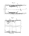
- Figures 6 to 10 illustrate the operation of the machine to produce a curved gallery.
- the machine is assumed in the configuration of FIG. 6.
- the axis X of the cutting kit 1 forms an angle a with the axis Y of the assembly skirt 2, this angle being a function of the curvature of the gallery to achieve.
- the jacks 7 are in the retracted state, those situated outside the curve having greater elongations adapted to the variable distances which separate the coupling points of the various jacks on the front support 6 and on the sliding ring 10 The latter is in its most forward position, pressing against the last coverings which have been put in place in the skirt (segments V).
- kit 1 and skirt 2 are in the position shown diagrammatically in FIG. 7. Shims of different lengths, as shown diagrammatically in broken lines at 27, can be put in place to block the skirt and the sharp kit in the appropriate angular configuration, defined by the differential elongation of the cylinders 7.
- These removable wedges can in particular be manually placed against the traction studs 5 in the slots of the coupling lugs 9. The set of wedges thus put in place allows, during the shield's progression movements, to keep precisely the value of the angle a between the X and Y axes of the case and the skirt.
- the jacks 7 are operated independently in the direction of the extension to move the shield forward. (figure 8). This movement is obtained by pressing the thrust ring 10 on the segments V which keep this ring stationary: under the thrust of the jacks 7, the cutting bag 1 is therefore caused to slide forward in the new length hollowed out and the assembly skirt 2 follows, the progression movement being transmitted to it by the traction studs 5 engaged with the lugs 9 as well as by the jacks 7 which link the cutting kit and the assembly skirt.
- the jacks 7 are retracted by maneuvering them independently so as to preserve their differential elongation (FIG. 9): the sliding ring is then brought back towards the front of the assembly skirt 2.
- Such a machine in which the cutting kit 1 and the assembly skirt 2 are capable of forming an angle reaching up to 4 ° makes it possible without difficulty to produce galleries having curvatures reaching up to 15 times their diameter; three people are enough to serve it and the average advancement can be around 5 meters per 8 hour shift.
Landscapes
- Engineering & Computer Science (AREA)
- Mining & Mineral Resources (AREA)
- Environmental & Geological Engineering (AREA)
- Life Sciences & Earth Sciences (AREA)
- General Life Sciences & Earth Sciences (AREA)
- Geochemistry & Mineralogy (AREA)
- Geology (AREA)
- Excavating Of Shafts Or Tunnels (AREA)
- Control Of Electric Motors In General (AREA)
- Separation By Low-Temperature Treatments (AREA)
Description
- L'invention concerne une machine perfectionnée pour la réalisation de galeries souterraines ; elle vise une machine permettant de creuser un boyau souterrain et de l'équiper progressivement, au fur et à mesure de l'avancement de la machine, d'éléments de revêtement soutenant les terres tels que tuyaux ou voussoirs.
- On connaît déjà de telles machines qui sont essentiellement composées d'un bouclier hydraulique et d'un dispositif d'abattage logé à l'intérieur du bouclier. Le dispositif d'abattage, généralement constitué par une fraise portée par un bras suspendu en partie haute du bouclier, permet de creuser et de fractionner la terre à l'avant du bouclier, cette terre étant éliminée vers l'arrière par un transporteur ; le bouclier hydraulique qui comprend un anneau de poussée sur lequel est attelé un système hydraulique de poussée, permet de faire progresser le bouclier après réalisation du terrassement avant approprié ; pour engendrer cette progression, l'anneau de poussée prend appui sur les tuyaux ou voussoirs déjà mis en place à l'arrière de la machine et le système hydraulique de poussée attelé à son autre extrémité sur le bouclier exerce sur ce dernier un effort d'avancement (US-A-4 190 294, US-A-4 203 626).
- De telles machines qui sont depuis longtemps bien connues des professionnels présentent plusieurs défauts auxquels on n'a pas su remédier jusqu'à présent.
- En premier lieu, les courbes sont très délicates à réaliser avec ce type de machine et nécessitent des terrassements hors profil de grandes sections et donc un personnel relativement important ; de plus, les courbes réalisées sont à très grands rayons (les rayons de courbure atteints étant généralement supérieurs à environ 100 fois le diamètre de la galerie). Au surplus, dans certains terrains très meubles, il s'avère parfois impossible de réaliser des courbes avec les machines connues et les professionnels sont obligés de recourir à des terrassements entièrement manuels. En outre, même en ligne droite, ces machines sont mal adaptées au creusement de terrains meubles qui ont tendance à « bourrer le dispositif d'abattage à fraise et à absorber des puissances très importantes.
- La présente invention se propose de remédier aux défauts des machines connues sus-évoquées, en fournissant une machine perfectionnée, conçue pour fonctionner suivant le même principe général que les machines connues.
- Un objectif essentiel de l'invention est en particulier d'autoriser la réalisation de courbes beaucoup plus prononcées et ce, sans avoir à effectuer des terrassements hors profils ; l'invention vise notamment à permettre de réaliser des courbes dont les rayons puissent être aisément ajustés jusqu'à une valeur minimum de l'ordre de 15 fois le diamètre de l'ouvrage.
- Un autre objectif est de fournir une machine adaptée pour travailler en tout terrain et notamment en terrain meuble aussi bien en lignes droites qu'en lignes courbes.
- Un objectif de l'invention est ainsi de fournir une machine universelle qui puisse, sans difficultés, creuser des galeries dans des terrains présentant des couches de natures différentes.
- A cet effet, la machine visée par l'invention est du type connu du US-A-4 190 294 et indiqué dans le préambule de la revendication 1 ; conformément à la présente invention, ladite machine est caractérisée en ce que ladite trousse coupante et ladite jupe d'assemblage sont liées entre elles par une fixation flottante adaptée pour les assujettir l'une à l'autre, d'une part, dans le sens longitudinal, d'autre part, en rotation autour de leur axe longitudinal, tout en autorisant un pivotement de faible amplitude de l'une par rapport à l'autre autour d'un axe orthogonal à leur axe longitudinal, de façon à permettre de les orienter l'une par rapport à l'autre dans une configuration angulaire telle que leurs axes longitudinaux forment un angle a ajustable.
- (II est à noter que les termes « avant » et « arrière se réfèrent au sens de progression de la machine ; en outre, les termes « horizontal et « vertical qui sont utilisés plus loin, supposent la machine en position de travail, les axes longitudinaux de la trousse coupante et de la jupe d'assemblage étant horizontaux).
- Selon un mode de réalisation préféré, la fixation flottante entre la trousse coupante et la jupe d'assemblage est adaptée de façon à permettre à ladite trousse et à ladite jupe un pivotement relatif ajustable jusqu'à une valeur de 4° environ.
- La fixation flottante précitée peut en particulier comprendre une pluralité de pattes d'accouplement et de plots de traction, répartis autour du bouclier et assujettis les uns à l'avant de la jupe d'assemblage, les autres à l'arrière de la trousse coupante, chaque plot de traction pénétrant dans une lumière d'une.patte d'accouplement avec un débattement adapté pour permettre le pivotement relatif précité entre ladite trousse coupante et ladite jupe d'assemblage.
- De plus, selon une autre caractéristique de l'invention, la trousse coupante comprend, solidarisée à sa partie arrière, une bague de centrage externe dans laquelle est emboîtée une bague de centrage interne solidarisée à l'avant de la jupe d'assemblage, lesdites bagues étant dimensionnées de façon à être espacées d'un jeu fonctionnel adapté pour autoriser le pivotement relatif précité entre la trousse coupante et la jupe d'assemblage.
- Le dispositif hydraulique de poussée du bouclier est avantageusement constitué par plusieurs vérins hydrauliques à commandes indépendantes, répartis autour du bouclier, chaque vérin étant attelé, à l'avant, sur un support annulaire solidaire de la trousse coupante et, à l'arrière, sur l'anneau de poussée coulissant dans la jupe d'assemblage.
- Ainsi, dans la machine conforme à l'invention, la partie avant du bouclier (trousse coupante) qui supporte le dispositif d'abattage peut être orientée selon une direction choisie de façon à former un angle ajustable par rapport à la partie arrière (jupe d'assemblage), laquelle permet la mise en place des éléments de revêtement. Le braquage de la trousse coupante est obtenu en commandant indépendamment les vérins de poussée au cours des manœuvres de progession du bouclier : les vérins situés du côté extérieur de la courbe à réaliser sont amenés à subir un allongement supérieur à ceux situés du côté intérieur, les rapports d'allongement définissant l'angle a de braquage. Le dispositif d'abattage peut ainsi travailler dans une direction angulaire décalée par rapport à la direction précédente, et ce, tout en autorisant, d'une part, un travail de type traditionnel au droit du profil de la trousse coupante, d'autre part, une mise en place classique des éléments de revêtement dans la jupe d'assemblage.
- Les essais ont démontré que l'obtention d'un angle de 4° entre la trousse coupante et la jupe d'assemblage, permet de réaliser des courbes de rayons s'abaissant jusqu'à environ 15 fois le diamètre du bouclier.
- Par ailleurs, selon d'autres caractéristiques de la machine perfectionnée conforme à l'invention, le dispositif d'abattage comprend comme il est déjà connu en principe de US-A-4 190 294 :
- un bâti fixe assujetti à l'intérieur de la trousse coupante et formant autour de l'axe de ladite trousse une plateforme sensiblement verticale,
- une couronne à roulement portée par ladite plateforme de façon que son axe coïncide sensiblement avec l'axe de la trousse coupante,
- un châssis tournant porté par la couronne à roulement précitée de façon à pouvoir pivoter sur 360°, sensiblement autour de l'axe de la trousse coupante,
- des moyens d'entraînement en rotation du châssis tournant,
- un bras d'abattage articulé sur le châssis tournant et doté à son extrémité d'un outil de travail, et un vérin hydraulique de manoeuvre dudit bras, attelé sur ledit bras et sur le châssis tournant de sorte que le point d'articulation du bras sur le châssis, le point d'attelage du vérin sur le châssis et le point d'attelage du vérin sur le bras ne soient jamais alignés.
- Comme on comprendra mieux plus loin, cette disposition permet au bras de balayer aisément la totalité de la section du front de taille (en avant de la trousse coupante) par le jeu combiné de la rotation sur 360° du bâti tournant et des manoeuvres du bras par rapport audit bâti tournant. De plus, l'outil peut être amené à travailler dans toutes les positions ; dans ces conditions, le bras est avantageusement équipé d'un godet apte à travailler en butte ou en rétro, qui permet de creuser sans difficulté aussi bien des terrains meubles que des terrains durs.
- En outre, selon une autre caractéristique de l'invention qui facilite la pénétration du godet dans les terres à l'avant de la trousse coupante, le bras d'abattage est télescopique et est équipé d'un vérin hydraulique permettant sa rétraction ou son extension.
- L'invention exposée ci-dessus dans sa forme générale sera mieux comprise à la lecture de la description qui suit et à l'examen des dessins annexés qui en présentent à titre non limitatif, un mode de réalisation sur ces dessins qui font partie intégrante de la présente description :
- la figure 1 est une coupe axiale par un plan vertical AA d'une machine conforme à l'invention,
- la figure 2 en est une coupe par un plan horizontal BB, le dispositif d'abattage n'étant pas coupé mais vu de dessus,
- la figure 3 est une coupe partielle par un plan transversal CC de ladite machine,
- les figures 4 et 5 sont des vues de détail d'un des éléments de la fixation flottante, respectivement vu de face et en coupe,
- les figures 6, 8, 9 et 10 sont des schémas explicatifs du fonctionnement de la machine, cependant que la figure 7 est un schéma montrant partiellement la fixation flottante dans la position de la figure 6 (il est à noter que, sur ces figures, l'angle entre la trousse coupante et la jupe d'assemblage a été exagéré pour mieux illustrer l'invention).
- La machine perfectionnée représentée à titre d'exemple aux figures 1, 2, 3, 4 et 5 est destinée à la réalisation de galeries souterraines, de diamètre pouvant varier entre 1,80 et 6 mètres. Cette machine comprend essentiellement, d'une part, un bouclier composé de deux pièces, une trousse coupante avant 1 et une jupe d'assemblage arrière 2, d'autre part, un dispositif d'abattage 3 porté par la trousse coupante 1.
- La trousse coupante 1 se présente sous la forme d'un tube cylindrique en acier pourvu d'une casquette supérieure 1a à sa partie avant ; à sa partie arrière, elle est dotée d'une bague de centrage externe 4 qui est soudée sur ladite trousse de façon que son épaisseur vienne en saillie à l'extérieur de la trousse 1, comme le montre la figure 5.
- De plus, plusieurs plots de traction tels que 5, par exemple au nombre de six, sont soudés intérieurement à l'arrière de la trousse coupante 1 et répartis sur le pourtour de celle-ci, au voisinage de sa jonction avec la bague 4.
- En outre, sur une portion intermédiaire de la trousse coupante 1 est soudée à l'intérieur de celle-ci un support annulaire 6 sur lequel sont articulés plusieurs vérins hydrauliques tels que 7 (par exemple au nombre de six), répartis sur le pourtour du bouclier. Le corps de chacun de ces vérins est articulé sur le support 6 par une chape classique.
- Par ailleurs, la jupe d'assemblage 2 se présente sous la forme d'un tube cylindrique en acier, dont le diamètre légèrement plus grand que celui de la trousse 1 est de l'ordre de celui de la bague externe 4 soudée à l'arrière de ladite trousse.
- A l'avant de la jupe 2, est soudée une bague de centrage interne 8 dont l'épaisseur vient en saillie à l'intérieur de ladite jupe comme le montre la figure 5. La bague 8 est emboîtée dans la bague 4, avec un jeu fonctionnel entre celles-ci, adapté pour autoriser un pivotement relatif de la trousse coupante par rapport à la jupe d'assemblage autour d'un axe quelconque orthogonal à l'axe de ces éléments. Les bagues 4 et 8 qui se recouvrent sur une distance longitudinale variable fonction de la position relative de la jupe et de la trousse, réalisent un guidage et un centrage relatif de ces éléments, évitant tout risque de décalage transversal.
- De plus, plusieurs pattes d'accouplement telles 9, en l'exemple au nombre de six, sont soudées intérieurement à l'avant de la bague de centrage 8, au niveau des plots de traction 5. Chaque patte d'accouplement 9 est dotée d'une lumière 9a, de dimension longitudinale très supérieure à celle d'un plot de traction 5 et de dimension transversale légèrement supérieure à celle de ce dernier. Chacun des plots 5 pénètre dans une lumière 9a d'une patte, de sorte que l'ensemble de ces organes constitue une fixation flottante assujetti- sant l'une à l'autre avec un débattement déterminé la jupe 2 et la trousse 1, d'une part, dans le sens longitudinal, tout en autorisant un pivotement de ces éléments de sorte que leurs axes longitudinaux forment un angle donné, cet angle pouvant aller jusqu'à une valeur maximum d'environ 4°.
- Par ailleurs, la jupe 2 guide un anneau de poussée 10 qui est monté coulissant dans celle-ci. Sur cet anneau sont attelés, de façon classique en soi, les tiges mobiles des vérins hydrauliques 7. Ces vérins sont équipés d'un système de distribution hydraulique permettant de les alimenter et de les commander indépendamment de façon à pouvoir régler individuellement leur allongement et ajuster ainsi la position angulaire relative de la trousse 1 par rapport à la jupe 2.
- Le dispositif d'abattage 3 porté par la trousse tranchante 1 comprend un bâti 11 possédant trois extensions en forme de tripode, par lesquelles il est fixé à l'intérieur de la trousse coupante 1, vers la portion arrière de celle-ci. Ce bâti forme autour de l'axe de la trousse une plateforme sensiblement verticale 11a, ledit bâti et sa plateforme étant évidés dans la région centrale de la trousse en vue de délimiter un volume central creux.
- Un châssis tournant 12 est monté à l'avant du bâti 11 sur la plateforme verticale 11 a par l'entremise d'une couronne à roulements de type connu, (symbolisée en 13 aux figures 1 et 2) ; cette couronne d'axe horizontal coïncidant avec l'axe de la trousse peut être du type à galets croisés, sa cage externe étant assujettie sur la plateforme 11a et sa cage interne sur le châssis 12. Cette dernière est dotée d'une denture 14 en prise avec un pignon 15 qui est articulé sur la plateforme 11 a et entraîné en rotation par un moteur hydraulique 16 porté à l'arrière par ladite plateforme 11a.
- Le châssis tournant 12 peut ainsi être entraîné en rotation sur 360° autour d'un axe horizontal coïncidant sensiblement avec l'axe de la trousse tranchante 1. Sur ce châssis tournant est articulé un bras d'abattage 18, par un axe 17 parallèle au plan de la plateforme 11a et situé au voisinage de celui-ci, cet axe d'articulation étant excentré par rapport au centre fictif de la plateforme. De plus, le bras d'abattage 18 comporte un prolongement arrière 18a qui vient se loger dans la partie creuse du bâti 11. Sur ce prolongement, est attelé par un axe 19 la tige mobile d'un vérin de manoeuvre 20. Ce vérin est incliné vers l'arrière comme le montre la figure 1 et son corps est attelé sur une extension avant 12a du châssis tournant, en un point d'attelage 21 situé à l'opposé du point d'articulation 17 du bras, par rapport à l'axe de la trousse tranchante.
- Le point d'articulation 17 du bras et les points d'attelages 19 et 21 du vérin de manoeuvre sont ainsi agencés en triangle et la disposition ci-dessus décrite de ces éléments permet à la fois de garantir une bonne efficacité du vérin de manoeuvre quelle que soit la position du bras 18 et de réduire considérablement l'encombrement à l'avant de la plateforme de façon à dégager l'aire de travail et à autoriser un balayage de toute la surface de cette aire par le bras (et ce, malgré la division du bouclier en deux pièces, qui conditionne une réduction notable de la dimension longitudinale de la trousse coupante dans laquelle est logé le dispositif d'abattage).
- Par ailleurs, le bras d'abattage 18 est avantageusement prévu télescopique et comprend deux membrures 18b, 18c montées coulissantes l'une par rapport à l'autre et un vérin hydraulique 22 situé à l'intérieur de ces dernières et attelé à celles-ci en vue de mouvoir la membrure 18b par rapport à la membrure 18c dans le sens d'une rétraction ou d'une extension longitudinale.
- La membrure 18b est équipée à son extrémité d'un godet 23 qui est associé à des moyens hydrauliques de manoeuvre classiques, comprenant un vérin hydraulique 24 et des bielles de transmission 25, en vue de permettre au godet d'être disposé aussi bien en position butte qu'en position rétro.
- Les différents vérins solidaires du châssis tournant 12 (vérins 20, 22 et 24) sont alimentés en huile sous pression par un joint tournant hydraulique de type classique 26.
- Le dispositif d'abattage ci-dessus décrit est apte à creuser efficacement aussi bien les terrains meubles que les terrains plus durs ; par le jeu du balayage du bras et de la rotation à 360°, le godet peut être amené à travailler indifféremment en butte ou en rétro, la nature télescopique du bras autorisant une bonne pénétration du godet vers l'avant.
- Un tel dispositif d'abattage est adapté à la structure en deux pièces distinctes du bouclier et est dépourvu des défauts des dispositifs classiques à fraise.
- La terre détachée par le dispositif est éliminée vers l'arrière, de façon traditionnelle, par un convoyeur qui a été schématisé en 27 aux figures 1, 2 et 3 ; ce convoyeur passe à travers une ouverture prévue dans le pied inférieur du bâti 11.
- Les figures 6 à 10 illustrent le fonctionnement de la machine pour réaliser une galerie courbe.
- Au début du cycle de fonctionnement, la machine est supposée dans la configuration de la figure 6. L'axe X de la trousse coupante 1 forme un angle a avec l'axe Y de la jupe d'assemblage 2, cet angle étant fonction de la courbure de la galerie à réaliser. Les vérins 7 sont à l'état rétracté, ceux situés à l'extérieur de la courbe ayant des allongements plus importants adaptés aux distances variables qui séparent les points d'attelage des divers vérins sur le support avant 6 et sur l'anneau coulissant 10. Ce dernier se trouve dans sa position la plus en avant, en appui contre les derniers revêtements qui ont été mis en place dans la jupe (voussoirs V).
- La fixation flottante entre trousse 1 et jupe 2 se trouve dans la position schématisée à la figure 7. Des cales de différentes longueurs, telles que schématisées en traits discontinus en 27, peuvent être mises en place pour bloquer la jupe et la trousse tranchante dans la configuration angulaire appropriée, définie par l'allongement différentiel des vérins 7. Ces cales amovibles peuvent en particulier être disposées manuellement contre les plots de traction 5 dans les lumières des pattes d'accouplement 9. L'ensemble des cales ainsi mises en place permet, au cours des mouvements de progression du bouclier, de conserver de façon précise la valeur de l'angle a entre les axes X et Y de la trousse et de la jupe.
- Lorsque le dispositif d'abattage (non schématisé à ces figures) a creusé une nouvelle longueur de boyau, les vérins 7 sont manoeuvrés indépendamment dans le sens de l'extension pour mouvoir le bouclier vers l'avant. (figure 8). Ce mouvement est obtenu grâce à l'appui de l'anneau de poussée 10 sur les voussoirs V qui maintiennent cet anneau immobile : sous la poussée des vérins 7, la trousse coupante 1 est donc amenée à glisser vers l'avant dans la nouvelle longueur creusée et la jupe d'assemblage 2 suit, le mouvement de progression lui étant transmis par les plots de traction 5 en prise avec les pattes 9 ainsi que par les vérins 7 qui lient la trousse coupante et la jupe d'assemblage.
- Lorsque la trousse coupante 1 est parvenue à l'extrémité de la longueur creusée, les vérins 7 sont rétractés en les manoeuvrant indépendamment de façon à préserver leur allongement différentiel (figure 9) : l'anneau coulissant est alors ramené vers l'avant de la jupe d'assemblage 2.
- Il suffit alors de monter, de façon traditionnelle, de nouveaux voussoirs (V') dans la jupe d'assemblage 2 et un nouveau cycle peut commencer (Figure 10).
- Une telle machine dans laquelle la trousse coupante 1 et la jupe d'assemblage 2 sont aptes à former un angle atteignant jusqu'à 4° permet de réaliser sans difficulté des galeries ayant des courbures atteignant jusqu'à 15 fois leur diamètre ; trois personnes suffisent pour la desservir et l'avancement moyen peut être de l'ordre de 5 mètres par poste de 8 heures.
Claims (12)
Priority Applications (1)
| Application Number | Priority Date | Filing Date | Title |
|---|---|---|---|
| AT83200603T ATE14777T1 (de) | 1982-06-02 | 1983-04-28 | Maschine zum unterirdischen streckenvortrieb. |
Applications Claiming Priority (2)
| Application Number | Priority Date | Filing Date | Title |
|---|---|---|---|
| FR8209835 | 1982-06-02 | ||
| FR8209835A FR2528108A1 (fr) | 1982-06-02 | 1982-06-02 | Machine perfectionnee a bouclier pour le creusement de galeries souterraines |
Publications (3)
| Publication Number | Publication Date |
|---|---|
| EP0095795A1 EP0095795A1 (fr) | 1983-12-07 |
| EP0095795B1 true EP0095795B1 (fr) | 1985-08-07 |
| EP0095795B2 EP0095795B2 (fr) | 1991-07-24 |
Family
ID=9274683
Family Applications (1)
| Application Number | Title | Priority Date | Filing Date |
|---|---|---|---|
| EP83200603A Expired - Lifetime EP0095795B2 (fr) | 1982-06-02 | 1983-04-28 | Machine perfectionnée pour la réalisation de galeries souterraines |
Country Status (5)
| Country | Link |
|---|---|
| US (1) | US4508390A (fr) |
| EP (1) | EP0095795B2 (fr) |
| AT (1) | ATE14777T1 (fr) |
| DE (1) | DE3360516D1 (fr) |
| FR (1) | FR2528108A1 (fr) |
Families Citing this family (14)
| Publication number | Priority date | Publication date | Assignee | Title |
|---|---|---|---|---|
| DE3342903C2 (de) * | 1983-11-26 | 1985-10-10 | Hochtief Ag Vorm. Gebr. Helfmann, 4300 Essen | Entkoppelungseinrichtung zum Entkoppeln der Bewegung des Vorlaufschildes und der Stirnschalung für eine Vortriebsmaschine |
| JPS61172993A (ja) * | 1985-01-29 | 1986-08-04 | 株式会社 イセキ開発工機 | シ−ルドトンネル掘進装置 |
| FR2589516B1 (fr) * | 1985-11-06 | 1988-05-20 | Bessac Creusement Soutenement | Procede et machine a bouclier pour le creusement de galeries souterraines, notamment dans des sols aquiferes a faible cohesion |
| JPH086551B2 (ja) * | 1989-07-19 | 1996-01-24 | 株式会社イセキ開発工機 | シールド型トンネル機械の方向修正装置 |
| DE3732261A1 (de) * | 1987-09-25 | 1989-04-06 | Bilfinger Berger Bau | Verfahren zur herstellung eines tunnels und schildvortriebsmaschine zur durchfuehrung des verfahrens |
| US4915453A (en) * | 1988-04-18 | 1990-04-10 | Fikse Tyman H | Floating shoe tunnel boring machine and boring process |
| IT1241160B (it) * | 1990-04-02 | 1993-12-29 | Carlo Grandori | Fresa a doppio scudo telescopico perfezionata. |
| US5221160A (en) * | 1990-04-26 | 1993-06-22 | Shimizuo Construction Co. | Subterranean connecting method for construction of shield tunnel and connecting apparatus therefor |
| FR2851009B1 (fr) * | 2003-02-10 | 2005-04-01 | Andre Boniface | Tunnelier a percussion apte a la realisation de tunnels a geometrie polygonale dans des sols tres durs |
| US7651170B2 (en) * | 2003-07-18 | 2010-01-26 | Rodney John Davies | Bore head for microbore operation |
| JP6249519B2 (ja) * | 2013-11-27 | 2017-12-20 | 株式会社奥村組 | シールド掘進機およびシールド掘進方法 |
| JP6425057B2 (ja) * | 2014-03-10 | 2018-11-21 | 清水建設株式会社 | 中折れ型トンネル掘削機の制御方法 |
| JP6498624B2 (ja) * | 2016-03-18 | 2019-04-10 | 公益財団法人鉄道総合技術研究所 | 掘削工法模擬装置 |
| JP6573142B2 (ja) * | 2018-07-24 | 2019-09-11 | 清水建設株式会社 | 中折れ型トンネル掘削機の制御方法 |
Family Cites Families (14)
| Publication number | Priority date | Publication date | Assignee | Title |
|---|---|---|---|---|
| FR1388527A (fr) * | 1964-04-15 | 1965-02-05 | Nii Osnovany I Podzemnikh Soor | Appareil pour le percement de tunnels |
| US3556599A (en) * | 1968-12-10 | 1971-01-19 | Tyman H Fikse | Method of tunneling and tunneling shield with a drag loader |
| DE2240967B2 (de) * | 1972-08-21 | 1976-06-10 | Weiss, Benedikt, 4200 Oberhausen | Verfahren und vorrichtung zum kurvenfoermigen vortrieb von stollen oder tunneln aus vorgefertigten betonrohren |
| DE2339702B2 (de) * | 1973-08-06 | 1975-07-10 | Gerhard Dipl.-Ing. 2090 Winsen Paproth | Vortriebsschild zum Auffahren röhrenförmiger unterirdischer Bauwerke mit Nennweiten unter 4 m |
| US3919851A (en) * | 1974-06-17 | 1975-11-18 | M & P Pipe Jacking Corp | Apparatus for the excavation and lining of subterranean tunnels |
| US4027903A (en) * | 1975-02-06 | 1977-06-07 | E. I. Du Pont De Nemours And Company | Water-degradable coupling member |
| US3966256A (en) * | 1975-04-11 | 1976-06-29 | The Robbins Company | Tunneling equipment |
| DE2545041A1 (de) * | 1975-10-08 | 1977-04-21 | Peiner Masch Schrauben | Vorrichtung zum lenken eines tunnelrohres |
| DE2621391A1 (de) * | 1976-05-14 | 1977-11-24 | Gewerk Eisenhuette Westfalia | Presstation, insbesondere zwischenpresstation, fuer einen rohrvorpressbetrieb |
| DE2736398C2 (de) * | 1977-08-12 | 1985-11-21 | Gewerkschaft Eisenhütte Westfalia, 4670 Lünen | Steuervorrichtung für einen Messerschild |
| DE2741637A1 (de) * | 1977-09-15 | 1979-03-22 | Goeppner Kaiserslautern Eisen | Vorrichtung zum vortrieb von tunnel- und stollenroehren |
| US4190294A (en) * | 1978-08-17 | 1980-02-26 | The Robbins Company | Excavator for use in a tunneling shield |
| US4203626A (en) * | 1979-02-21 | 1980-05-20 | Zokor Corporation | Articulated boom-dipper-bucket assembly for a tunnel boring machine |
| DE2952744C2 (de) * | 1979-12-29 | 1985-01-10 | Bade & Theelen Gmbh, 3160 Lehrte | In der Richtung lenkbarer Schildmantel einer Vortriebsmaschine |
-
1982
- 1982-06-02 FR FR8209835A patent/FR2528108A1/fr active Granted
-
1983
- 1983-04-28 AT AT83200603T patent/ATE14777T1/de active
- 1983-04-28 DE DE8383200603T patent/DE3360516D1/de not_active Expired
- 1983-04-28 EP EP83200603A patent/EP0095795B2/fr not_active Expired - Lifetime
- 1983-06-01 US US06/500,413 patent/US4508390A/en not_active Expired - Lifetime
Also Published As
| Publication number | Publication date |
|---|---|
| ATE14777T1 (de) | 1985-08-15 |
| EP0095795B2 (fr) | 1991-07-24 |
| US4508390A (en) | 1985-04-02 |
| FR2528108B1 (fr) | 1985-03-08 |
| EP0095795A1 (fr) | 1983-12-07 |
| DE3360516D1 (en) | 1985-09-12 |
| FR2528108A1 (fr) | 1983-12-09 |
Similar Documents
| Publication | Publication Date | Title |
|---|---|---|
| EP0095795B1 (fr) | Machine perfectionnée pour la réalisation de galeries souterraines | |
| EP0017593B1 (fr) | Engin pour le curage des étangs, marais ou canaux | |
| EP1533470A1 (fr) | Tête de foration et de boulonnage pour machine de boulonnage | |
| FR2463258A1 (fr) | Perforatrice guidee par affut ou par mat | |
| FR2888859A1 (fr) | Installation de realisation de paroi enterree par melange du sol avec un liant et procede de correction de trajectoire de la tete de forage d'une telle installation | |
| EP1632638B1 (fr) | Foreuse hydraulique pour travaux en espace réduit | |
| FR2595107A1 (fr) | Vehicule de type pelleteuse a pivotement complet a rayon reduit pour faciliter les operations dans un site resserre | |
| FR2944300A1 (fr) | Engin motorise pour creuser une tranchee dans le sol et poser, dans celle-ci, des objets allonges | |
| EP0021987A1 (fr) | Machine pour le creusement des galeries souterraines | |
| FR2493370A1 (fr) | Bras articule pour engin d'excavation | |
| CH622058A5 (en) | Machine for digging galleries or tunnels | |
| EP3241985A1 (fr) | Tunnelier | |
| FR2816166A1 (fr) | Machine robotisee de taille d'arbustes ou d'arbres tels que des arbres fruitiers | |
| FR2466604A1 (fr) | Machine de forage pour realiser des trous dans le sol | |
| FR3050758B1 (fr) | Tunnelier | |
| FR2506830A1 (fr) | Tariere pendulaire | |
| EP0114146B1 (fr) | Machine de forage polyvalente dotée de moyens de remontée rapide du train de tiges | |
| EP0631032B1 (fr) | Tunnelier à creusement frontal pleine section | |
| EP2206876B1 (fr) | Tête de forage pour machine de forage | |
| FR2539157A1 (fr) | Trancheuse a fleche | |
| FR2663980A1 (fr) | Colonne perforatrice verticale. | |
| FR2512102A1 (fr) | Cylindre de coupe comprenant un dispositif de pulverisation | |
| FR2624197A1 (fr) | Procede et dispositif pour nettoyer une tariere, et machine de forage par tariere | |
| EP0696673B1 (fr) | Machine de havage pour le prédécoupage de la voûte d'une galerie | |
| FR2624899A1 (fr) | Machine pour le creusage de rigoles sur le bord des routes, pour l'evacuation de l'eau |
Legal Events
| Date | Code | Title | Description |
|---|---|---|---|
| PUAI | Public reference made under article 153(3) epc to a published international application that has entered the european phase |
Free format text: ORIGINAL CODE: 0009012 |
|
| AK | Designated contracting states |
Designated state(s): AT BE CH DE GB IT LI LU NL SE |
|
| 17P | Request for examination filed |
Effective date: 19840118 |
|
| ITF | It: translation for a ep patent filed |
Owner name: ORGANIZZAZIONE D'AGOSTINI |
|
| GRAA | (expected) grant |
Free format text: ORIGINAL CODE: 0009210 |
|
| AK | Designated contracting states |
Designated state(s): AT BE CH DE GB IT LI LU NL SE |
|
| PG25 | Lapsed in a contracting state [announced via postgrant information from national office to epo] |
Ref country code: NL Effective date: 19850807 Ref country code: AT Effective date: 19850807 |
|
| REF | Corresponds to: |
Ref document number: 14777 Country of ref document: AT Date of ref document: 19850815 Kind code of ref document: T |
|
| PG25 | Lapsed in a contracting state [announced via postgrant information from national office to epo] |
Ref country code: SE Effective date: 19850830 |
|
| REF | Corresponds to: |
Ref document number: 3360516 Country of ref document: DE Date of ref document: 19850912 |
|
| NLV1 | Nl: lapsed or annulled due to failure to fulfill the requirements of art. 29p and 29m of the patents act | ||
| PG25 | Lapsed in a contracting state [announced via postgrant information from national office to epo] |
Ref country code: LU Free format text: LAPSE BECAUSE OF NON-PAYMENT OF DUE FEES Effective date: 19860430 |
|
| PLBI | Opposition filed |
Free format text: ORIGINAL CODE: 0009260 |
|
| 26 | Opposition filed |
Opponent name: GEWERKSCHAFT EISENHUETTE WESTFALIAGMBH Effective date: 19860507 |
|
| PG25 | Lapsed in a contracting state [announced via postgrant information from national office to epo] |
Ref country code: LI Effective date: 19870430 Ref country code: CH Effective date: 19870430 |
|
| GBPC | Gb: european patent ceased through non-payment of renewal fee | ||
| REG | Reference to a national code |
Ref country code: CH Ref legal event code: PL |
|
| PLAB | Opposition data, opponent's data or that of the opponent's representative modified |
Free format text: ORIGINAL CODE: 0009299OPPO |
|
| PG25 | Lapsed in a contracting state [announced via postgrant information from national office to epo] |
Ref country code: GB Effective date: 19881122 |
|
| R26 | Opposition filed (corrected) |
Opponent name: GEWERKSCHAFT EISENHUETTE WESTFALIA GMBH Effective date: 19860507 |
|
| PUAH | Patent maintained in amended form |
Free format text: ORIGINAL CODE: 0009272 |
|
| STAA | Information on the status of an ep patent application or granted ep patent |
Free format text: STATUS: PATENT MAINTAINED AS AMENDED |
|
| 27A | Patent maintained in amended form |
Effective date: 19910724 |
|
| AK | Designated contracting states |
Kind code of ref document: B2 Designated state(s): AT BE CH DE GB IT LI LU NL SE |
|
| APAC | Appeal dossier modified |
Free format text: ORIGINAL CODE: EPIDOS NOAPO |
|
| APAC | Appeal dossier modified |
Free format text: ORIGINAL CODE: EPIDOS NOAPO |
|
| PGFP | Annual fee paid to national office [announced via postgrant information from national office to epo] |
Ref country code: BE Payment date: 20020524 Year of fee payment: 20 |
|
| PGFP | Annual fee paid to national office [announced via postgrant information from national office to epo] |
Ref country code: DE Payment date: 20020529 Year of fee payment: 20 |
|
| BE20 | Be: patent expired |
Owner name: *FONCAGES ET FORAGES BESSAC S.A. Effective date: 20030428 |
|
| APAH | Appeal reference modified |
Free format text: ORIGINAL CODE: EPIDOSCREFNO |