EP0094534A1 - Rauchdetektor nach dem Strahlungs-Extinktions-Prinzip - Google Patents
Rauchdetektor nach dem Strahlungs-Extinktions-Prinzip Download PDFInfo
- Publication number
- EP0094534A1 EP0094534A1 EP83104219A EP83104219A EP0094534A1 EP 0094534 A1 EP0094534 A1 EP 0094534A1 EP 83104219 A EP83104219 A EP 83104219A EP 83104219 A EP83104219 A EP 83104219A EP 0094534 A1 EP0094534 A1 EP 0094534A1
- Authority
- EP
- European Patent Office
- Prior art keywords
- smoke detector
- detector according
- radiation
- pulses
- reference voltage
- Prior art date
- Legal status (The legal status is an assumption and is not a legal conclusion. Google has not performed a legal analysis and makes no representation as to the accuracy of the status listed.)
- Granted
Links
Images

Classifications
-
- G—PHYSICS
- G08—SIGNALLING
- G08B—SIGNALLING OR CALLING SYSTEMS; ORDER TELEGRAPHS; ALARM SYSTEMS
- G08B17/00—Fire alarms; Alarms responsive to explosion
- G08B17/10—Actuation by presence of smoke or gases, e.g. automatic alarm devices for analysing flowing fluid materials by the use of optical means
- G08B17/103—Actuation by presence of smoke or gases, e.g. automatic alarm devices for analysing flowing fluid materials by the use of optical means using a light emitting and receiving device
-
- G—PHYSICS
- G08—SIGNALLING
- G08B—SIGNALLING OR CALLING SYSTEMS; ORDER TELEGRAPHS; ALARM SYSTEMS
- G08B29/00—Checking or monitoring of signalling or alarm systems; Prevention or correction of operating errors, e.g. preventing unauthorised operation
- G08B29/02—Monitoring continuously signalling or alarm systems
- G08B29/04—Monitoring of the detection circuits
- G08B29/043—Monitoring of the detection circuits of fire detection circuits
Definitions
- the invention relates to a smoke detector with a pulsed radiation source which emits a bundled beam into an area freely accessible to the ambient air, a radiation receiver arranged in the beam, the downstream input amplifier of which generates receive pulses which are proportional to the received radiation intensity, and an evaluation circuit which has a reference voltage associated with it the receiving pulses is compared, has a supplying element, an alarm stage which triggers an alarm signal for longer than a certain period of time when the received pulses weaken below a predetermined alarm threshold, and a fault mare which, in the event of a weakening of the received pulses triggering an alarm signal, more rapid weakening of the received pulses below a fault threshold less than the alarm threshold triggers a fault signal.
- Such a smoke detector is known, for example, from DE-OS 2,822,547.
- the radiation source and radiation receiver are accommodated in two different housings, which are attached to the walls of the room to be monitored at different distances depending on the place of use.
- a fixed alarm threshold is specified. However, this corresponds to very different smoke densities when the distance between the radiation source and receiver is different.
- the invention is based on the object of providing a smoke detector whose sensitivity does not depend, or only insignificantly, on the distance between the radiation source and the receiver. Furthermore, changes in the operating state due to contamination, aging and temperature fluctuations are to be rendered ineffective.
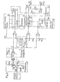
- FIGS 1 and 2 show circuit examples of preferred embodiments.
- the radiation source 3 in this case a light or infrared radiation emitting diode (LED), is activated by the pulse generator 1 via a driver stage 2.
- the current is preferably regulated with the aid of the reference radiation receiver 4 in such a way that the radiation intensity of the pulses assumes a fixed value.
- T22, R21 and R23 switch the current through LED 3, which is supplied by the capacitor C21.
- C21 is recharged between the pulses via R24.
- T21 and R22 regulate the radiation intensity in connection with the reference radiation receiver 4.
- the radiation pulses falling on the radiation receiver 5 are amplified by the input amplifier 6 and fed to three comparison circuits 7, 8, 9.
- a two-stage transistor amplifier T61, T62 whose operating point is determined by the resistors R61, R62, and R64, is sufficient as the input amplifier.
- the differential resistance of the diode D61 together with the feedback resistor R 63 and the resistor R62 determine the gain.
- the quiescent current through the diode D61 and thus its differential resistance is determined by the voltage U v and the resistor R65. In this way, the gain of the input amplifier 6 can be controlled.
- the entire amplifier is separated by coupling capacitors C61 and C63.
- the output of the input amplifier 6 is connected to the positive input of the comparison circuit 9.
- the voltage U s (interference threshold), which is obtained from the reference voltage U ref with the voltage divider R1, R2, 14, is present at the negative input.
- a correlation pulse appears at the output of the comparison circuit 9, which is passed on to the clock inputs C of the counters 10 and 15.
- the capacitance C161 is also discharged with the correlation pulse in the fault circuit 16 with the aid of R161 and T161. If there are no correlation pulses, ie if the output pulses of the input amplifier no longer reach the interference threshold U s , the capacitance C161 is charged via the resistor R162 and an error signal 19 is emitted by the logic circuit 17.
- the comparison circuit 7 compares the signal at the output of the input amplifier 6 (receive pulses) with the reference voltage U ref . Its output controls the counting direction U / D of the up-down counter 11.
- the digital value Q 0 ... Q l of the counter is converted in the digital-to-analog converter 12 into an analog voltage, from which a non-linear amplifier 13 the control voltage U v for the amplification of the input amplifier 6 is generated.
- the counter reading is increased or decreased by one in accordance with the value of the output of the comparison circuit 7.
- the gain of the input amplifier 6 is changed so that the difference between the level of the Receive pulses and the reference voltage becomes practically zero.
- the binary counter 10 divides the frequency of the correlation pulses by a certain factor and uses them to generate the clock pulses of the up-down counter 11.
- the tracking becomes slow enough to not or only insignificantly compensate for changes in the reception pulses due to the increase in smoke density, but nevertheless due to changes slow dusting, aging and temperature fluctuations. If the up-down counter 11 reaches its lower or upper limit (zero or 2 l + 1 - 1), further tracking is no longer possible.
- a fault signal can be derived from the negated carry-out output C out , which assumes the value zero at the counter limits. This value is processed by the logic circuit 17 and a fault signal 19 is generated.
- Another comparison circuit 8 compares the received pulses E (output of the input amplifier) with the alarm threshold U A. The output of this comparison circuit controls the reset input of the alarm delay counter 15. If the received pulses fall below the alarm threshold U A , the alarm delay counter 15 is no longer reset and the correlation pulses increase the counter reading. After a certain number of pulses, an alarm signal 18 is emitted, on the other hand, due to the logic circuit 17, only if a fault signal 19 is not also present at the same time.
- the state of the up-down counter 11 corresponds to a determined gain of the input amplifier 6, and thus a certain intensity of radiation at the radiation receiver 5.
- This radiation intensity is again a good M ass for the distance between the radiation source 3 and receiver 5, as they are inversely proportional to the Square of this distance.
- the counter reading Q o ... Q Q is therefore characteristic of a specific distance between the radiation source and receiver.
- the digitally controllable resistor 14 is from the counter stand controlled and thus the ratio of alarm threshold to reference voltage is adjusted to the different distances. The functional dependence of this ratio on the distance is now preferably chosen such that the alarm threshold always corresponds to the same smoke density. This is possible by a suitable definition of the transfer function of the non-linear amplifier 13.
- FIG. 2 shows a further circuit of a smoke detector according to the invention.
- the pulse generator 1 controls the radiation source 3 via the driver stage 2.
- T22 and R21 switch the current through the radiation source 3, which is supplied by the capacitance C21, which in turn is charged between the pulses via the resistor R24.
- the current through the radiation source is regulated to a specific value with the aid of the zener diode D21 and the resistor R23.
- the radiation pulses falling on the radiation receiver 5 are amplified by the input amplifier 6 and fed to the three comparison circuits 7, 8, 9.
- This amplifier 6 consists of an operational amplifier A61 and the variable feedback resistor R63, with which the gain can be set to a suitable value when the smoke detector is started up.
- the coupling capacitance C61 separates DC components.
- the processing of the outputs of the comparison circuits 7, 8, 9 takes place in the same way as in FIG. 1. Reference is made to their description.
- the output of the digital-to-analog converter 12, on the other hand, is not used to control the input amplifier, but rather represents the reference voltage U ref directly.
- the (slow) change in the counter reading of the up-down counter 11, the reference voltage U ref is adjusted so that the difference between the level of the received pulses and the reference voltage becomes practically zero.
- the ratio of the alarm threshold to the reference voltage can be set by the variable resistor 14.
- a switch 141 is provided, which changes the resistance value of the resistor 14 by connecting the resistors R141 or R142 in parallel to R143.
- a continuously variable resistor eg potentiometer
- the smoke detectors described have a significantly improved stability even over longer periods of time. Slow changes due to dust, aging of the components and temperature fluctuations are automatically compensated for by a tracking mechanism, without the risk of an incorrect alarm triggering and without loss of sensitivity. They are also characterized by a better defined sensitivity, in that the ratio of the alarm threshold to the reference voltage is adapted to the distance between the radiation source and receiver.
Landscapes
- Physics & Mathematics (AREA)
- General Physics & Mathematics (AREA)
- Engineering & Computer Science (AREA)
- Computer Security & Cryptography (AREA)
- Chemical & Material Sciences (AREA)
- Analytical Chemistry (AREA)
- Business, Economics & Management (AREA)
- Emergency Management (AREA)
- Fire-Detection Mechanisms (AREA)
- Investigating Or Analysing Materials By Optical Means (AREA)
Abstract
Description
- Die Erfindung betrifft einen Rauchdetektor mit einer impulsweise betriebenen Strahlungsquelle, welche einen gebündelten Strahl in ein der Umgebungsluft frei zugängliches Gebiet aussendet, einem im Strahl angeordneten Strahlungsempfänger, dessen nachgeschalteter Eingangsverstärker der empfangenen Strahlungsintensität proportionale Empfangsimpulse erzeugt und einer Auswerteschaltung, welche ein eine Referenzspannung, die mit den Empfangsimpulsen verglichen wird, lieferndes Element aufweist, eine Alarmstufe, die bei Abschwächung der Empfangsimpulse unter eine vorgegebene Alarmschwelle länger als eine bestimmte Zeitdauer ein Alarmsignal auslöst, aufweist und eine Störungsstute, die bei einer gegenüber der ein Alarmsignal auslösenden Abschwächung der Empfangsimpulse schnelleren Abschwächung der Empfangsimpulse unter eine Störungsschwelle kleiner als die Alarmschwelle ein Störungssignal auslöst, aufweist.
- Ein solcher Rauchdetektor ist beispielsweise aus der DE-OS 2'822'547 bekannt. Bei dem dort beschriebenen Rauchmelder sind - wie bei diesen sogenannten "Linienextinktionsmeldern" üblich - Strahlungsquelle und Strahlungsempfänger in zwei verschiedenen Gehäusen untergebracht, welche je nach Einsatzort mit verschiedenem Abstand an den Wänden des zu überwachenden Raumes befestigt werden. Es ist eine feste Alarmschwelle vorgegeben. Diese entspricht aber bei unterschiedlichem Abstand zwischen Strahlungsquelle und -empfänger ganz unterschiedlichen Rauchdichten.
- Der Erfindung liegt die Aufgabe zu Grunde, einen Rauchdetektor zu schaffen, dessen Empfindlichkeit nicht oder nur unerheblich vom Abstand zwischen Strahlungsquelle und Empfänger abhängt. Weiter sollen Veränderungen des Betriebszustandes durch Verschmutzung, Alterung und Temperaturschwankungen unwirksam gemacht werden.
- Diese Aufgabe wird bei einem Rauchdetektor der eingangs erwähnten Gattung erfindungsgemäss durch die im kennzeichnenden Teil des Patentanspruches 1 definierten Merkmale gelöst. Bevorzugte Ausführungsformen und weitere Ausgestaltungen der Erfindung sind in den abhängigen Ansprüchen definiert.
- Die Erfindung wird im folgenden an Hand der Zeichnungen näher erläutert.
- Die Figuren 1 und 2 zeigen Schaltungsbeispiele bevorzugter Ausführungsformen.
- In Figur 1 wird die Strahlugsquelle 3, in diesem Falle eine Licht oder infrarote Strahlung emittierende Diode (LED), über eine Treiberstufe 2 vom Pulsgenerator 1 angesteurt. Vorzugsweise wird der Strom mit Hilfe des Referenzstrahlungsempfängers 4 so geregelt, dass die Strahlungsintensität der Impulse einen festen Wert annimmt. T22, R21 und R23 schalten den Strom durch die LED 3, welcher von der Kapazität C21 geliefert wird. C21 wird zwischen den Pulsen über R24 wieder aufgeladen. T21 und R22 regeln in Verbindung mit dem Referenzstrahlungsempfänger 4 die Strahlungsintensität.
- Die auf den Strahlungsempfänger 5 fallenden Strahlungsimpulse werden vom Eingangsverstärker 6 verstärkt und drei Vergleichsschaltungen 7, 8, 9 zugeführt. Als Eingangsverstärker genügt ein zweistufiger Transistorverstärker T61, T62, dessen Arbeitspunkt durch die Widerstände R61, R62, und R64 bestimmt wird. Der differentielle Widerstand der Diode D61 zusammen mit dem Rückkopplungswiderstand R 63 und dem Widerstand R62 bestimmen die Verstärkung. Der Ruhestrom durch die Diode D61 und damit ihr differentieller Widerstand, wird durch die Spannung Uv und den Widerstand R65 bestimmt. Auf diese Art kann die Verstärkung des Eingangsverstärkers 6 gesteuert werden. Der ganze Verstärker ist durch Kopplungskapazitäten C61 und C63 abgetrennt.
- Der Ausgang des Eingangsverstärkers 6 wird an den positiven Eingang der Vergleichsschaltung 9 gelegt. Am negativen Eingang liegt die Spannung Us (Störungsschwelle), welche mit dem Spannungsteiler R1, R2, 14 aus der Referenzspannung Uref gewonnen wird. Am Ausgang der Vergleichsschaltung 9 erscheint bei Anwesenheit eines Strahlungsimpulses ein Korrelationsimpuls, welcher an die Clock-Eingänge C der Zähler 10 und 15 weitergegeben wird. Ebenfalls mit dem Korrelationsimpuls wird in der Störungsschaltung 16 mit Hilfe von R161 und T161 die Kapazität C161 entladen. Bei Ausbleiben von Korrelationsimpulsen, d.h. falls die Ausgangsimpulse des Eingangsverstärkers die Störungsschwelle Us nicht mehr erreichen, wird die Kapazität C161 über den Widerstand R162 aufgeladen und durch die Logikschaltung 17 ein Störungssignal 19 abgegeben.
- Die Vergleichsschaltung 7 vergleicht das Signal am Ausgang des Eingangsverstärkers 6 (Empfangsimpulse) mit der Referenzspannung Uref. Ihr Ausgang steuert die Zählrichtung U/D des Vorwärts-Rückwärts-Zählers 11. Der Digitalwert Q0 ... Qℓ des Zählers wird im Digital-Analog-Wandler 12 in eine analoge Spannung umgewandelt, aus welcher mit einem nicht-linearen Verstärker 13 die Steuerspannung Uv für die Verstärkung des Eingangsverstärkers 6 erzeugt wird. Bei jedem Clock-Impuls des Zählers 11 wird entsprechend dem Wert des Ausganges der Vergleichsschaltung 7 der Zählerstand um Eins erhöht oder erniedrigt. Dadurch wird die Verstärkung des Eingangsverstärkers 6 so verändert, dass die Differenz zwischen der Höhe der Empfangsimpulse und der Referenzspannung praktisch null wird. Der Binärzähler 10 dividiert die Frequenz der Korrelationsimpulse durch einen bestimmten Faktor und erzeugt daraus die Clock-Impulse des Vorwärts-Rückwärts-Zählers 11. So wird die Nachführung genügend langsam, um Aenderungen der Empfangsimpulse zufolge Rauchdichteanstiegs nicht oder nur unwesentlich auszugleichen, wohl aber Aenderungen zufolge langsamer Verstaubung, Alterung und Temperaturschwankungen. Stösst der Vorwärts-Rückwärts-Zähler 11 an seine untere oder obere Grenze (Null oder 2ℓ+1 - 1) ist eine weitere Nachführung nicht mehr möglich. Ein Störungssignal kann vom negierten Carry-Out-Ausgang Cout abgeleitet werden, welcher an den Zählergrenzen den Wert Null annimmt. Durch die Logikschaltung 17 wird dieser Wert verarbeitet und ein Störungssignal 19 erzeugt.
- Eine weitere Vergleichsschaltung 8 vergleicht die Empfangsimpulse E (Ausgang des Eingangsverstärkers) mit der Alarmschwelle UA. Der Ausgang dieser Vergleichsschaltung steuert den Reset-Eingang des Alarmverzögerungszählers 15. Falls die Empfangsimpulse die Alarmschwelle UA unterschreiten, wird der Alarmverzögerungszähler 15 nicht mehr zurückgestellt und die Korrelationsimpulse erhöhen den Zählerstand. Nach einer bestimmten Anzahl Pulse wird ein Alarmsignal 18 abgegeben, aufgrund der Logikschaltung 17 hingegen nur falls nicht gleichzeitig auch ein Störungssignal 19 vorhanden ist.
- Der Stand des Vorwärts-Rückwärts-Zählers 11 entspricht einer bestimmten Verstärkung des Eingangsverstärkers 6 und damit einer bestimmten Strahlungsintensität am Strahlungsempfänger 5. Diese Strahlungsintensität ist wiederum ein gutes Mass für den Abstand zwischen Strahlungsquelle 3 und -empfänger 5, da sie sich umgekehrt proportional zum Quadrat dieses Abstandes verhält. Der Zählerstand Qo ... QQ ist daher charakteristisch für eine bestimmte Distanz zwischen Strahlungsquelle und -empfänger. Der digital steuerbare Widerstand 14 wird vom Zählerstand gesteuert und somit wird das Verhältnis von Alarmschwelle zu Referenzspannung den verschiedenen Distanzen angepasst. Die funktionelle Abhängigkeit dieses Verhältnisses von der Distanz wird nun vorzugsweise so gewählt, dass die Alarmschwelle immer der gleichen Rauchdichte entspricht. Dies ist durch eine geeignete Festlegung der Uebertragungsfunktion des nicht-linearen Verstärkers 13 möglich.
- Figur 2 zeigt eine weitere Schaltung eines Rauchmelders gemäss der Erfindung. Der Pulsgenerator 1 steuert über die Treiberstufe 2 die Strahlungsquelle 3. T22 und R21 schalten den Strom durch die Strahlungsquelle 3, welcher von der Kapazität C21 geliefert wird, welche ihrerseits über den Widerstand R24 zwischen den Pulsen aufgeladen wird. Bei dieser Ausführungsform der Treiberstufe 2 wird, im Gegensatz zur in Figur 1 dargestellten, der Strom durch die Strahlungsquelle mit Hilfe der Zenerüiode D21 und dem Widerstand R23 auf einen bestimmten Wert geregelt.
- Die auf den Strahlungsempfänger 5 fallenden Strahlungsimpulse werden vom Eingangsverstärker 6 verstärkt und den drei Vergleichsschaltungen 7, 8, 9 zugeführt. Dieser Verstärker 6 besteht aus einem Operationsverstärker A61 und dem veränderbaren Rückkopplungswiderstand R63, mit welchem die Verstärkung bei Inbetriebnahme des Rauchmelders auf einen geeigneten Wert eingestellt werden kann. Die Kopplungskapazität C61 trennt Gleichstromkomponenten ab.
- Die Verarbeitung der Ausgänge der Vergleichsschaltungen 7, 8, 9 erfolgt auf dieselbe Weise wie in Figur 1. Es sei auf ihre Beschreibung verwiesen. Der Ausgang des Digital-Analog-Wandlers 12 hingegen wird nicht zur Steuerung des Eingangsverstärkers benutzt, sondern stellt direkt die Referenzspannung Uref dar. Durch die (langsame) Veränderung des Zählerstandes des Vorwärts-Rückwärts-Zählers 11 wird die Referenzspannung Uref so nachgeführt, dass die Differenz zwischen der Höhe der Empfangsimpulse und Referenzspannung praktisch null wird. Das Verhältnis von Alarmschwelle zu Referenzspannung kann durch den veränderbaren Widerstand 14 eingestellt werden. In diesem Falle ist ein Schalter 141 vorgesehen, welcher durch Parallelschaltung der Widerstände R141 oder R142 zu R143 den Widerstandswert des Widerstandes 14 verändert. Es ist aber auch möglich, diese Einrichtung durch einen kontinuierlich veränderbaren Widerstand (z.B. Potentiometer) zu ersetzen.
- Die beschriebenen Rauchmelder weisen eine wesentlich verbesserte Stabilität auch über längere Zeiträume auf. Langsame Aenderungen durch Verstaubung, Alterung der Komponenten und Temperaturschwankungen werden durch einen Nachführmechanismus automatisch kompensiert, ohne die Gefahr einer fehlerhaften Alarmauslösung und ohne Empfindlichkeitsverlust. Weiter zeichnen sie sich durch eine besser definierte Empfindlichkeit aus, indem das Verhältnis von Alarmschwelle zu Referenzspannung der Distanz zwischen Strahlungsquelle und -empfänger angepasst wird.
Claims (13)
Applications Claiming Priority (2)
| Application Number | Priority Date | Filing Date | Title |
|---|---|---|---|
| CH297382 | 1982-05-13 | ||
| CH2973/82 | 1982-05-13 |
Publications (2)
| Publication Number | Publication Date |
|---|---|
| EP0094534A1 true EP0094534A1 (de) | 1983-11-23 |
| EP0094534B1 EP0094534B1 (de) | 1987-01-14 |
Family
ID=4245793
Family Applications (1)
| Application Number | Title | Priority Date | Filing Date |
|---|---|---|---|
| EP83104219A Expired EP0094534B1 (de) | 1982-05-13 | 1983-04-29 | Rauchdetektor nach dem Strahlungs-Extinktions-Prinzip |
Country Status (8)
| Country | Link |
|---|---|
| US (1) | US4559453A (de) |
| EP (1) | EP0094534B1 (de) |
| JP (1) | JPS58214997A (de) |
| CA (1) | CA1208335A (de) |
| DE (1) | DE3369213D1 (de) |
| ES (1) | ES8404535A1 (de) |
| NO (1) | NO159967C (de) |
| ZA (1) | ZA833436B (de) |
Cited By (6)
| Publication number | Priority date | Publication date | Assignee | Title |
|---|---|---|---|---|
| GB2158278A (en) * | 1984-03-05 | 1985-11-06 | Hochiki Co | Photoelectric smoke sensor |
| EP0596500A1 (de) * | 1992-11-04 | 1994-05-11 | Nohmi Bosai Ltd. | Rauchdetektierungsvorrichtung für Feueralarm |
| AU654438B2 (en) * | 1992-05-25 | 1994-11-03 | Nohmi Bosai Ltd | Fire detector |
| WO2013014561A1 (de) * | 2011-07-22 | 2013-01-31 | Shustrov Sergei Vladimirovich | Pulsbetriebener rauchdetektor mit digitaler steuereinheit |
| CN113538837A (zh) * | 2021-07-08 | 2021-10-22 | 深圳市豪恩安全科技有限公司 | 光电感烟探测方法、探测装置及计算机可读存储介质 |
| CN113990023A (zh) * | 2021-10-26 | 2022-01-28 | 无锡商业职业技术学院 | 一种用于光电式烟雾探测器的自校准、补偿电路和方法 |
Families Citing this family (16)
| Publication number | Priority date | Publication date | Assignee | Title |
|---|---|---|---|---|
| FI854809A (fi) * | 1984-12-18 | 1986-06-19 | Hochiki Co | Branddetektor som baserar sig pao minskat ljus. |
| US5144286A (en) * | 1990-08-06 | 1992-09-01 | Allen-Bradley Company, Inc. | Photosensitive switch with circuit for indicating malfunction |
| US5502434A (en) * | 1992-05-29 | 1996-03-26 | Hockiki Kabushiki Kaisha | Smoke sensor |
| US5543777A (en) * | 1993-07-12 | 1996-08-06 | Detection Systems, Inc. | Smoke detector with individual sensitivity calibration and monitoring |
| US5552765A (en) * | 1993-07-12 | 1996-09-03 | Detection Systems, Inc. | Smoke detector with individually stored range of acceptable sensitivity |
| JPH09270085A (ja) * | 1996-04-01 | 1997-10-14 | Hamamatsu Photonics Kk | 発煙検知装置 |
| GB2319604A (en) * | 1996-11-25 | 1998-05-27 | Kidde Fire Protection Ltd | Smoke and particle detector |
| US6504750B1 (en) * | 2001-08-27 | 2003-01-07 | Micron Technology, Inc. | Resistive memory element sensing using averaging |
| US6826102B2 (en) * | 2002-05-16 | 2004-11-30 | Micron Technology, Inc. | Noise resistant small signal sensing circuit for a memory device |
| US6813208B2 (en) * | 2002-07-09 | 2004-11-02 | Micron Technology, Inc. | System and method for sensing data stored in a resistive memory element using one bit of a digital count |
| AU2003268142A1 (en) * | 2002-08-23 | 2004-03-11 | General Electric Company | Rapidly responding, false detection immune alarm signal producing smoke detector |
| KR100778153B1 (ko) | 2006-11-14 | 2007-11-22 | 주식회사 가스트론 | 수신반까지의 전선의 길이에 적응하여 출력전류를 일정하게조절하는 회로를 가진 가스누설 감지기 |
| US8742937B2 (en) * | 2007-07-19 | 2014-06-03 | Hochiki Corporation | Alarm unit |
| WO2012008627A1 (ko) | 2010-07-13 | 2012-01-19 | 볼보 컨스트럭션 이큅먼트 에이비 | 건설기계의 선회 제어 장치 및 그 방법 |
| GB2537940B (en) | 2015-05-01 | 2018-02-14 | Thorn Security | Fire detector drift compensation |
| EP3704679A1 (de) * | 2017-10-30 | 2020-09-09 | Carrier Corporation | Kompensator in einer detektorvorrichtung |
Citations (3)
| Publication number | Priority date | Publication date | Assignee | Title |
|---|---|---|---|---|
| DE2822547A1 (de) * | 1977-05-23 | 1978-12-07 | Hochiki Co | Vorrichtung zur ueberpruefung des schwebstoffgehalts der atmosphaere, insbesondere zur verwendung als rauchmelder |
| US4185278A (en) * | 1977-09-22 | 1980-01-22 | HF Systems, Incorporated | Obscuration type smoke detector |
| GB2059128A (en) * | 1979-08-24 | 1981-04-15 | Hochiki Co | Photoelectric smoke sensors |
Family Cites Families (5)
| Publication number | Priority date | Publication date | Assignee | Title |
|---|---|---|---|---|
| US4011458A (en) * | 1975-10-09 | 1977-03-08 | Pyrotector, Incorporated | Photoelectric detector with light source intensity regulation |
| JPS5829558B2 (ja) * | 1977-05-23 | 1983-06-23 | ホーチキ株式会社 | 減光式感知器 |
| GB2044504B (en) * | 1979-03-17 | 1983-04-20 | Hochiki Co | Count discriminating fire detector |
| JPS56133548A (en) * | 1980-03-25 | 1981-10-19 | Shigeo Kobayashi | Fan device for air exhaust |
| JPS5722541A (en) * | 1980-07-15 | 1982-02-05 | Matsushita Electric Works Ltd | Light reduction type smoke sensor |
-
1983
- 1983-04-29 DE DE8383104219T patent/DE3369213D1/de not_active Expired
- 1983-04-29 EP EP83104219A patent/EP0094534B1/de not_active Expired
- 1983-05-04 CA CA000427475A patent/CA1208335A/en not_active Expired
- 1983-05-05 US US06/491,707 patent/US4559453A/en not_active Expired - Fee Related
- 1983-05-11 NO NO831682A patent/NO159967C/no unknown
- 1983-05-13 JP JP58082849A patent/JPS58214997A/ja active Granted
- 1983-05-13 ZA ZA833436A patent/ZA833436B/xx unknown
- 1983-05-13 ES ES522683A patent/ES8404535A1/es not_active Expired
Patent Citations (3)
| Publication number | Priority date | Publication date | Assignee | Title |
|---|---|---|---|---|
| DE2822547A1 (de) * | 1977-05-23 | 1978-12-07 | Hochiki Co | Vorrichtung zur ueberpruefung des schwebstoffgehalts der atmosphaere, insbesondere zur verwendung als rauchmelder |
| US4185278A (en) * | 1977-09-22 | 1980-01-22 | HF Systems, Incorporated | Obscuration type smoke detector |
| GB2059128A (en) * | 1979-08-24 | 1981-04-15 | Hochiki Co | Photoelectric smoke sensors |
Non-Patent Citations (1)
| Title |
|---|
| PATENTS ABSTRACTS OF JAPAN, Band 3, Nr. 34, 22. März 1979, Seite 127 E 99 & JP - A - 54 12878 (MATSUSHITA DENKO K.K.) 30.01.1979 * |
Cited By (9)
| Publication number | Priority date | Publication date | Assignee | Title |
|---|---|---|---|---|
| GB2158278A (en) * | 1984-03-05 | 1985-11-06 | Hochiki Co | Photoelectric smoke sensor |
| AT388059B (de) * | 1984-03-05 | 1989-04-25 | Hochiki Co | Photoelektrischer rauchsensor |
| AU654438B2 (en) * | 1992-05-25 | 1994-11-03 | Nohmi Bosai Ltd | Fire detector |
| EP0596500A1 (de) * | 1992-11-04 | 1994-05-11 | Nohmi Bosai Ltd. | Rauchdetektierungsvorrichtung für Feueralarm |
| WO2013014561A1 (de) * | 2011-07-22 | 2013-01-31 | Shustrov Sergei Vladimirovich | Pulsbetriebener rauchdetektor mit digitaler steuereinheit |
| EA026448B1 (ru) * | 2011-07-22 | 2017-04-28 | Сергей Владимирович Шустров | Импульсно работающий детектор дыма с цифровым управляющим модулем |
| CN113538837A (zh) * | 2021-07-08 | 2021-10-22 | 深圳市豪恩安全科技有限公司 | 光电感烟探测方法、探测装置及计算机可读存储介质 |
| CN113538837B (zh) * | 2021-07-08 | 2022-09-13 | 深圳市豪恩安全科技有限公司 | 光电感烟探测方法、探测装置及计算机可读存储介质 |
| CN113990023A (zh) * | 2021-10-26 | 2022-01-28 | 无锡商业职业技术学院 | 一种用于光电式烟雾探测器的自校准、补偿电路和方法 |
Also Published As
| Publication number | Publication date |
|---|---|
| US4559453A (en) | 1985-12-17 |
| NO831682L (no) | 1983-11-14 |
| CA1208335A (en) | 1986-07-22 |
| JPS58214997A (ja) | 1983-12-14 |
| DE3369213D1 (en) | 1987-02-19 |
| NO159967B (no) | 1988-11-14 |
| EP0094534B1 (de) | 1987-01-14 |
| ES522683A0 (es) | 1984-04-16 |
| JPH0441395B2 (de) | 1992-07-08 |
| ZA833436B (en) | 1984-01-25 |
| NO159967C (no) | 1989-02-22 |
| ES8404535A1 (es) | 1984-04-16 |
Similar Documents
| Publication | Publication Date | Title |
|---|---|---|
| EP0094534B1 (de) | Rauchdetektor nach dem Strahlungs-Extinktions-Prinzip | |
| DE3328256C2 (de) | Verfahren und Anordnung zur automatischen Stabilisierung eines Szintillationsdetektors | |
| EP0218011B1 (de) | Schaltungsanordnung für einen Infrarot-Raumüberwachungs-Detektor | |
| DE4310168A1 (de) | Schaltung zum Alarm-Stummschalten von photoelektrischen Rauchdetektoren | |
| DE2526171A1 (de) | Vorrichtung zur raumsicherung | |
| DE2032438B2 (de) | Vorrichtung zur regelung des vorspannstromes fuer einen photodetektor | |
| DE2822547A1 (de) | Vorrichtung zur ueberpruefung des schwebstoffgehalts der atmosphaere, insbesondere zur verwendung als rauchmelder | |
| DE3931038A1 (de) | Lichtschranke | |
| DE2722982B1 (de) | Schaltungsanordnung fuer eine nach dem Doppler-Prinzip arbeitende Ultraschall-Einbruchssicherungsanlage | |
| DE2462876C2 (de) | Rauchdetektor | |
| EP0292804B1 (de) | Schaltungsanordnung zur potentialfreien Erfassung von binären Signalen | |
| EP0079010A1 (de) | Rauchdetektor | |
| DE2738198A1 (de) | Vorrichtung zur erfassung der aenderung einer gewaehlten bedingung | |
| DE2750388A1 (de) | Mikrowellen-nachweisvorrichtung mit einem gleichzeitig als detektor arbeitenden gunn-oszillator | |
| EP0098552B1 (de) | Verfahren und Einrichtung zur automatischen Abfrage des Meldermesswerts und der Melderkennung in einer Gefahrenmeldeanlage | |
| DE10049994A1 (de) | Schaltungsanordnung zum Überwachen und/oder zum Einstellen von Versorgungsspannungen | |
| DE3536701C2 (de) | Vorrichtung zur Überwachung der Funktion einer Sirene | |
| EP0039080B1 (de) | Sender für impulsförmige Hochfrequenzsignale | |
| CH674074A5 (de) | ||
| DE3131490A1 (de) | Naeherungsschalter | |
| DE3136629C2 (de) | ||
| EP0267302B1 (de) | Schaltungseinrichtung für eine Meldeeinrichtung zur Raumüberwachung | |
| DE2914266C2 (de) | Photoelektrische Einrichtung zum Erzeugen eines einer Nutzlichtänderung entsprechenden elektrischen Ausgangssignales | |
| DE3803034C2 (de) | ||
| DE3404151C2 (de) |
Legal Events
| Date | Code | Title | Description |
|---|---|---|---|
| PUAI | Public reference made under article 153(3) epc to a published international application that has entered the european phase |
Free format text: ORIGINAL CODE: 0009012 |
|
| 17P | Request for examination filed |
Effective date: 19830429 |
|
| AK | Designated contracting states |
Designated state(s): BE CH DE FR GB IT LI NL SE |
|
| ITF | It: translation for a ep patent filed |
Owner name: VETTOR GALLETTI DI SAN CATALDO |
|
| GRAA | (expected) grant |
Free format text: ORIGINAL CODE: 0009210 |
|
| AK | Designated contracting states |
Kind code of ref document: B1 Designated state(s): BE CH DE FR GB IT LI NL SE |
|
| REF | Corresponds to: |
Ref document number: 3369213 Country of ref document: DE Date of ref document: 19870219 |
|
| ET | Fr: translation filed | ||
| PGFP | Annual fee paid to national office [announced via postgrant information from national office to epo] |
Ref country code: NL Payment date: 19870430 Year of fee payment: 5 |
|
| PLBE | No opposition filed within time limit |
Free format text: ORIGINAL CODE: 0009261 |
|
| STAA | Information on the status of an ep patent application or granted ep patent |
Free format text: STATUS: NO OPPOSITION FILED WITHIN TIME LIMIT |
|
| 26N | No opposition filed | ||
| BERE | Be: lapsed |
Owner name: CERBERUS A.G. Effective date: 19880430 |
|
| PG25 | Lapsed in a contracting state [announced via postgrant information from national office to epo] |
Ref country code: NL Effective date: 19881101 |
|
| NLV4 | Nl: lapsed or anulled due to non-payment of the annual fee | ||
| PG25 | Lapsed in a contracting state [announced via postgrant information from national office to epo] |
Ref country code: BE Effective date: 19890430 |
|
| PGFP | Annual fee paid to national office [announced via postgrant information from national office to epo] |
Ref country code: FR Payment date: 19940309 Year of fee payment: 12 |
|
| PGFP | Annual fee paid to national office [announced via postgrant information from national office to epo] |
Ref country code: SE Payment date: 19940315 Year of fee payment: 12 |
|
| PGFP | Annual fee paid to national office [announced via postgrant information from national office to epo] |
Ref country code: GB Payment date: 19940316 Year of fee payment: 12 |
|
| PGFP | Annual fee paid to national office [announced via postgrant information from national office to epo] |
Ref country code: DE Payment date: 19940406 Year of fee payment: 12 |
|
| PGFP | Annual fee paid to national office [announced via postgrant information from national office to epo] |
Ref country code: CH Payment date: 19940617 Year of fee payment: 12 |
|
| EAL | Se: european patent in force in sweden |
Ref document number: 83104219.7 |
|
| PG25 | Lapsed in a contracting state [announced via postgrant information from national office to epo] |
Ref country code: GB Effective date: 19950429 |
|
| PG25 | Lapsed in a contracting state [announced via postgrant information from national office to epo] |
Ref country code: SE Effective date: 19950430 Ref country code: LI Effective date: 19950430 Ref country code: CH Effective date: 19950430 |
|
| REG | Reference to a national code |
Ref country code: CH Ref legal event code: PL |
|
| PG25 | Lapsed in a contracting state [announced via postgrant information from national office to epo] |
Ref country code: FR Effective date: 19951229 |
|
| GBPC | Gb: european patent ceased through non-payment of renewal fee |
Effective date: 19950429 |
|
| PG25 | Lapsed in a contracting state [announced via postgrant information from national office to epo] |
Ref country code: DE Effective date: 19960103 |
|
| EUG | Se: european patent has lapsed |
Ref document number: 83104219.7 |
|
| REG | Reference to a national code |
Ref country code: FR Ref legal event code: ST |