EP0094311B1 - Vorrichtung zum Trocknen von ausgelegtem Material - Google Patents
Vorrichtung zum Trocknen von ausgelegtem Material Download PDFInfo
- Publication number
- EP0094311B1 EP0094311B1 EP83400921A EP83400921A EP0094311B1 EP 0094311 B1 EP0094311 B1 EP 0094311B1 EP 83400921 A EP83400921 A EP 83400921A EP 83400921 A EP83400921 A EP 83400921A EP 0094311 B1 EP0094311 B1 EP 0094311B1
- Authority
- EP
- European Patent Office
- Prior art keywords
- area
- drying
- upstream
- downstream
- areas
- Prior art date
- Legal status (The legal status is an assumption and is not a legal conclusion. Google has not performed a legal analysis and makes no representation as to the accuracy of the status listed.)
- Expired
Links
- 239000000463 material Substances 0.000 title claims abstract description 77
- 238000001035 drying Methods 0.000 title claims abstract description 71
- 238000011144 upstream manufacturing Methods 0.000 claims abstract description 47
- 239000007789 gas Substances 0.000 claims abstract description 27
- 238000000034 method Methods 0.000 claims abstract description 10
- 241000289669 Erinaceus europaeus Species 0.000 description 19
- 238000009434 installation Methods 0.000 description 15
- 239000004459 forage Substances 0.000 description 4
- 230000001174 ascending effect Effects 0.000 description 2
- 238000011084 recovery Methods 0.000 description 2
- 241000196324 Embryophyta Species 0.000 description 1
- 238000007599 discharging Methods 0.000 description 1
- 230000010355 oscillation Effects 0.000 description 1
- 239000003973 paint Substances 0.000 description 1
- 239000011505 plaster Substances 0.000 description 1
- 230000000717 retained effect Effects 0.000 description 1
- 238000004904 shortening Methods 0.000 description 1
Images
Classifications
-
- F—MECHANICAL ENGINEERING; LIGHTING; HEATING; WEAPONS; BLASTING
- F26—DRYING
- F26B—DRYING SOLID MATERIALS OR OBJECTS BY REMOVING LIQUID THEREFROM
- F26B19/00—Machines or apparatus for drying solid materials or objects not covered by groups F26B9/00 - F26B17/00
-
- F—MECHANICAL ENGINEERING; LIGHTING; HEATING; WEAPONS; BLASTING
- F26—DRYING
- F26B—DRYING SOLID MATERIALS OR OBJECTS BY REMOVING LIQUID THEREFROM
- F26B17/00—Machines or apparatus for drying materials in loose, plastic, or fluidised form, e.g. granules, staple fibres, with progressive movement
-
- F—MECHANICAL ENGINEERING; LIGHTING; HEATING; WEAPONS; BLASTING
- F26—DRYING
- F26B—DRYING SOLID MATERIALS OR OBJECTS BY REMOVING LIQUID THEREFROM
- F26B25/00—Details of general application not covered by group F26B21/00 or F26B23/00
- F26B25/001—Handling, e.g. loading or unloading arrangements
- F26B25/002—Handling, e.g. loading or unloading arrangements for bulk goods
-
- F—MECHANICAL ENGINEERING; LIGHTING; HEATING; WEAPONS; BLASTING
- F26—DRYING
- F26B—DRYING SOLID MATERIALS OR OBJECTS BY REMOVING LIQUID THEREFROM
- F26B3/00—Drying solid materials or objects by processes involving the application of heat
- F26B3/02—Drying solid materials or objects by processes involving the application of heat by convection, i.e. heat being conveyed from a heat source to the materials or objects to be dried by a gas or vapour, e.g. air
- F26B3/06—Drying solid materials or objects by processes involving the application of heat by convection, i.e. heat being conveyed from a heat source to the materials or objects to be dried by a gas or vapour, e.g. air the gas or vapour flowing through the materials or objects to be dried
Definitions
- the present invention relates to the drying of spreadable materials in a bed, in particular fodder, with a large flow of air. It more specifically aims to reduce the cost of equipment by allowing the installation of drying in low installations in which the drying beds are coplanar.
- the conventional installation consists in using perforated conveyor belts circulating in opposite directions, the material to be dried being brought to the upstream end of a conveyor belt and transferred to the downstream end thereof on the upstream end of the carpet flowing in the opposite direction, the gas flow passing through the conveyor belt and the bed of material which it carries.
- the conveyor belts are superimposed and the material falls from the highest conveyor belt onto the conveyor immediately below the downstream end of each conveyor belt.
- the degree of dryness of the material increases as it goes down in the stages. The material is in movement during the entire drying process, the transport equipment is complex and expensive and this movement does not improve the efficiency of the exchange of moisture between the material and the drying gas.
- DE-A-3 006 126 describes a device of this type in which, in order to be able to have beds of material to be dried on the two strands of the chain, the latter consists of flaps which are released at the end of the chain close to a deflection roller to drop the material carried by the flap which opens on the other strand of the same chain or on the upper strand of the chain placed below.
- DE-A-2 209 013 Also known from DE-A-2 209 013 is an installation in which the material is spread on an upper drying area constituted by shutters and after a first drying stage it falls on the drying area situated below and thus immediately from area to area, all of the drying areas being traversed by an ascending stream of drying air.
- US-A-2050477 describes a similar installation, the superimposed areas each consisting of a plurality of oscillating plates with which cooperate scanning means which cause, during each oscillation, to drop the material carried on a plate of the area located in below.
- the object of the present invention is to propose an installation for drying spreadable materials in gas-permeable beds, according to the counter-current method, which greatly reduces the investments necessary for the implementation of the previously known methods in which the material to be dried is circulated, continuously or step by step, during the drying period, in a zigzag course parallel to the largest dimension of the surface of the bed and perpendicular to the direction of flow of the gas flow drying.
- the installation for drying materials spreadable in gas-permeable beds according to the counter-current method according to the invention which comprises a plurality of perforated drying areas arranged parallel to each other and in series along the circulation path drying gas so that they pass successively through the gas flow, with means for bringing the material subjected to drying to the upstream area which is furthest downstream in the gas flow, and means for transferring it from area to area, up to the most downstream area which is furthest upstream in the gas flow from where means evacuate it in the dry state
- the perforated drying areas are fixed and coplanar and in that the installation includes means for bringing the material subjected to drying to the upstream area most downstream in the gas flow, means which move above said area in the greatest direction of the areas and deposit the material to be dried in successive sections of said upstream drying area and means for transfer from area to area which take the material in a section from the upstream area and transfer it to a section of the downstream area from which the material has been removed to be transferred to the area further downstream or to be evacuated
- the transfer of the material from the upstream area to the downstream area can be achieved by a first movable chassis along the length of the upstream area and carrying a pickup device picking up across the width of the upstream area in front of the chassis and a spreading device spreading the material to be dried over the width of the upstream area behind the frame and a second frame movable along the length of the downstream area and carrying a pickup device picking up across the width of the area downstream in front of the second chassis and a spreading device spreading the material collected by the collecting device of the upstream area over the width of the downstream area behind the second chassis and means for transporting the material collected by the device of collecting the first chassis to the spreading device of the second chassis.
- the two frames can be joined in the form of a carriage spanning the two areas and carrying the means of transport arranged transversely. It is also possible to provide two independent carriages moving in opposite directions over the areas while occupying homologous positions, the means of transport being constituted by conveyors parallel to the areas with a means of transfer from the upstream area to the downstream area located at the end of the upstream area.
- the material can be brought to the device for spreading the upstream area and evacuated from the device for collecting the downstream area by skips carried by the movable frame of the upstream area and the movable frame of the downstream area respectively. It is also possible to provide conveyors arranged parallel to the drying areas.
- the duration of transport of a load representing only a very small part of the total duration of the drying, handling and transport of the material to be dried are provided by a single carriage moving on rails above the various drying areas, this carriage comprising a loading platform, recovery means capable of taking up the fodder on a surface for loading it on this platform and means for spreading the loading of fodder being on this platform.
- the two drying areas constituted by a perforated sheet or a mesh AV and AM are arranged side by side and only the parts of these areas where the transfer of the material to be dried is in progress have been schematized .
- the AM area is the upstream area on which the fresh material is and the AV area is the downstream area on which drying ends.
- the gas flow G in practice air which, for example, is heated by passing over the hot exchanger of a heat pump, is brought under the AV area and ascends upwards the bed of material already rid of part of its humidity carried by this area then it crosses in an ascending manner, as shown schematically by the arrows G, the bed of more humid material carried by the upstream area AM to be taken up below this area.
- RAM designates the reservoir for supplying the material to be dried and REV designates the reservoir for discharging the dry material, an example of which will be described in more detail below but which could also be continuous conveyors such as conveyor belts transporting the material in the direction of arrow F.
- These tanks as well as the means of distribution and recovery on the areas and of transfer from area to area which will be described schematically below circulate in the direction of the arrows F.
- the material to be dried brought into the RAM tank is distributed over the section a 1 to constitute the bed A 1 behind the device.
- the bed of material A 2 already half dried and which is on the upstream area AM in front of the device is taken up in section a 2 located in front of a 1 to be transferred to section a 3 of the area of AV drying to constitute the bed of material A 3 behind the device and the bed of material A 4 at the final dryness which is on the downstream area AV in front of the device is taken up to be loaded into the REV drain tank.
- the RAM supply tank is loaded with material to be dried at the upstream end of the drying areas and the dry material is removed from the REV tank downstream from the drying areas.
- the details of the device may vary depending on the nature of the material to be dried and a device suitable for drying the fodder will be described more particularly below.
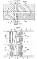
- the AM-AV drying areas each consist of a perforated sheet 1 carried by longitudinal beams forming rails 2 of circulation for the carriage and extended downwards by aprons to constitute supply and return air tunnels for drying.
- the sheets 1 are reinforced by crosspieces 3.
- the carriage frame and the rollers on the rails 2 as well as the drive means are not shown to simplify the drawings.
- the frame carries, by bearings 4-5, two parallel axes 6 and 7.
- the two axes are driven in the same direction shown by arrows in the figures.
- the front axis 6 carries a hedgehog whose teeth 8 come to tangent the surface of the perforated sheet 1 so as to pick up the forage lying in bed on the area and to project it, with the help of a guide plate 9 and deflecting teeth 10, on a conveyor belt 11 disposed transversely to the carriage and the upper strand of which flows from the area AM towards the area AV as represented by the arrow F 1 .
- a sheet 12 across the width of the AM area prevents the material from being projected beyond the conveyor.
- the rear axis 7 carries a hedgehog equalizing the bed, the teeth 13 of which are spaced from the sheet 1 of the thickness of the bed.
- a chute 14 Behind the sheet 12 and in front of the hedgehog 13 opens a chute 14 whose rear edge is extended by deflecting teeth 15 interposed between the teeth of the hedgehog 13.
- the chute 14 is located at the base of an enclosure 16 forming a reserve of spreadable fodder for a start of drying on the upstream area AM.
- a conveyor belt 17 At the bottom of the enclosure and over its entire width is mounted a conveyor belt 17 provided with teeth 17a which paint the base of the load and bring the material to the opening of the chute 14, the material being deflected towards the chute by deflecting teeth 18.
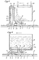
- the axis 6 carries the return cylinder 19 of a lifting belt 20 provided with projecting teeth 21.
- a deflecting plate 22 cooperates with the lifting belt 20 to prevent the dried material being found on the AV area and taken up by the teeth 21 of the lifting belt, falls back on said area.
- the material is projected by centrifugal force when the belt passes over the upper return cylinder 24 and it falls into an enclosure 25 intended to collect the dry material.
- Teeth 26 which engage between the teeth 21 of the lifting belt release the material which could stuff between said teeth.
- At the top of the tank 25 is mounted an endless belt 27 which can be driven in the direction of the arrow or lowered by jacks 28. The purpose of this conveyor belt is to spread the pile of material over the entire surface of the tank 25 and compact the material to reduce its volume.
- the shaft 7 carries a hedgehog whose teeth 30 pass over the upper surface of the sheet 1 at a distance equal to the thickness of the bed. Deflecting teeth 31 prevent the material from stuffing around the hedgehog 30.
- the enclosure 25 is empty and the enclosure 16 is loaded with material, for example fodder to be dried.
- material for example fodder to be dried.
- the truck is started.
- the fodder beds which were on the areas are picked up by the lifting belt 20-21 for the dry fodder located on the downstream area AV and by the hedgehog 8 for the semi-dried fodder found on the upstream area AM .
- the dry fodder raised by the lifting belt 20-21 is poured into the enclosure 25.
- the semi-dry fodder picked up by the hedgehog 8 is projected onto the conveyor belt 11 which brings it above the downstream area AV on which it is spread by the sheet 29 and the hedgehog 30, this area having been freed from the dry fodder treated during the preceding half-period by the lifting belt 20-21.
- the fodder to be dried being in the enclosure 16 is spread by the chute 14 and the hedgehog 13 on the upstream drying area AM which has been freed from the half-dried fodder during the preceding half-drying period by the hedgehog 8.
- the homologous sections are symmetrical with respect to a point P located between the areas equidistant from their ends. Namely, the fodder to be dried being supplied with M and the dry fodder discharged at S, the fodder supplied with M is deposited in a section a, 'which was released during the previous cycle and the semi-dried fodder is collected in the section a 2 'close to a i ' to be spread in section a 3 'released during the previous cycle, the dry fodder in section a; neighbor being picked up to be evacuated in S.
- the above embodiment of the method can be implemented with a trans device single carrier, pick-up and spreader, for example of the type described with reference to FIGS. 6 and 7, which moves on rails forming a circuit above the drying areas and the loading and unloading devices S.
- the meaning of forward movement is the direction of arrow C, FIG. 5.
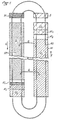
- the carriage comprises bogies 41 with rollers 42 some of which are motors which carry the frame 43. Under this frame hangs a transport platform 44 at a end of which is mounted the drum 45 of a pick-up 46 whose teeth pass between bars 47.
- the platform 44 is suspended from the frame, at the end corresponding to the pick-up, by fixed points 48 created by bars 49, fixed points around which levers 50 are articulated, one of the arms of which rotates the axis 51 of the pick-up while the other arm is actuated by a jack 52 acting between its end 53 and the frame 43 At its other end, platform 44 is suspended from the end 54 of a jack 55 articulated at 56 on the frame 43.
- the platform 44 can thus be raised, lowered and tilted longitudinally.
- a spreading hedgehog 57 is suspended by an oscillating bar 58 from the frame 43, the position of the hedgehog relative to the neighboring edge of the platform being adjustable by means of a jack 59.
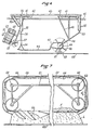
- the spreading and the equalization of the batch are ensured by a spreader designated as a whole by the reference 60 in FIG. 7.
- This spreader comprises a frame 61 secured to the arm 58 which carries four axes 62 on which pinions 63 are mounted, at least one of which is driven from the hedgehog axis 57; these sprockets guide two endless chains 64.
- On said endless chains are mounted regularly spaced axes 65 which carry flaps 66 directed towards the rear and capable of coming into abutment on the rear axis 65.
- the assembly is surrounded by a casing 67 which surrounds the two vertical strands and the upper strand of the chain, this casing being closed on its vertical face opposite to the hedgehog 57.
- the endless chains of the spreader device rotate in the direction of the arrow H so that the axis of articulation of the flaps 66 is located in front.
- the hedgehog 57 projects the fodder which is brought against it by sliding on the platform 44 suitably inclined by extension of the jack 52 and adjustment of the jack 59, above the lower strand of the chains without end 64 in the housing 67. If there is no bed formed on the perforated plate 68 on which the bed L is formed or if the thickness of the bed is small as illustrated in the left part of the figure 7, the flaps 66 hang freely and the projected fodder passes freely between them. When, on the other hand, the fodder bed rises, the flaps 66 gradually rise and brake then stop the passage of the fodder which is retained in bed F above the flaps. Detectors of any known type detect the raising position of all the flaps 66, which corresponds to a bed L formed over the entire width of the drying area 68, and control the advancement of the device.
- the device of FIG. 6 raised by lengthening the jack 52 and shortening the jack 55 so that it can circulate freely above the beds, is brought to station M where it receives, on the platform 44, a load of fodder corresponding to the quantity spread over an area a '.
- the device is then brought above the area a ' i , the pick-up 46 being, in the site plan adopted, in front of the device and the spreader device in the rear.
- the carriage In line with the downstream end of the area a ' i , the carriage is stopped, the spreading device is placed in a position of cooperation with the end of the platform 44 and the fodder is sent by the hedgehog 57 into the spreader 60.
- the carriage moves rearwards with respect to arrow C (Fig. 5) to spread its load over the entire area a ' 1 .
- the pick-up 47 is then brought to the right of the edge of the area a ′ 2 on which the partially dried fodder is located.
- the end of the platform 44 carrying the pick-up is lowered, this lowering being limited by stop rollers 69.
- the pick-up is then started and the device advances to scan the area at ' 2 and load the forage on this area onto platform 44.
- the load can be equalized by tilting, using the jacks, the loading platform.
- the loaded forage is then spread on section a ' 3 as described above for section a' 1 and the completely dry forage in section a ' 4 is loaded on platform 44 and unloaded in S to be evacuated.
- the device described with reference to Figures 6 and 7 can also be used in the case of a number of drying areas greater than two.
Landscapes
- Engineering & Computer Science (AREA)
- Mechanical Engineering (AREA)
- General Engineering & Computer Science (AREA)
- Life Sciences & Earth Sciences (AREA)
- Microbiology (AREA)
- Drying Of Solid Materials (AREA)
- Processing Of Solid Wastes (AREA)
- Steroid Compounds (AREA)
- Fodder In General (AREA)
- Apparatuses For Bulk Treatment Of Fruits And Vegetables And Apparatuses For Preparing Feeds (AREA)
Claims (5)
Priority Applications (1)
| Application Number | Priority Date | Filing Date | Title |
|---|---|---|---|
| AT83400921T ATE19300T1 (de) | 1982-05-10 | 1983-05-06 | Vorrichtung zum trocknen von ausgelegtem material. |
Applications Claiming Priority (2)
| Application Number | Priority Date | Filing Date | Title |
|---|---|---|---|
| FR8208063A FR2526531B1 (fr) | 1982-05-10 | 1982-05-10 | Procede de sechage de matieres etalables en lit, notamment de fourrages et installation pour sa mise en oeuvre |
| FR8208063 | 1982-05-10 |
Publications (2)
| Publication Number | Publication Date |
|---|---|
| EP0094311A1 EP0094311A1 (de) | 1983-11-16 |
| EP0094311B1 true EP0094311B1 (de) | 1986-04-16 |
Family
ID=9273867
Family Applications (1)
| Application Number | Title | Priority Date | Filing Date |
|---|---|---|---|
| EP83400921A Expired EP0094311B1 (de) | 1982-05-10 | 1983-05-06 | Vorrichtung zum Trocknen von ausgelegtem Material |
Country Status (7)
| Country | Link |
|---|---|
| EP (1) | EP0094311B1 (de) |
| JP (1) | JPS5941770A (de) |
| AT (1) | ATE19300T1 (de) |
| CS (1) | CS251076B2 (de) |
| DE (1) | DE3363022D1 (de) |
| FR (1) | FR2526531B1 (de) |
| OA (1) | OA07424A (de) |
Families Citing this family (3)
| Publication number | Priority date | Publication date | Assignee | Title |
|---|---|---|---|---|
| GR1003348B (el) * | 1999-03-15 | 2000-03-29 | Μοναδα αφυδατωσης χυδην προιοντων | |
| CZ19179U1 (cs) | 2008-10-23 | 2008-12-16 | Tarpo Spol. S R.O. | Zarízení pro kontinuální sušení cásticových materiálu |
| CN115978919B (zh) * | 2022-12-30 | 2023-07-21 | 山东省国宠宠物食品有限责任公司 | 宠物饲料真空烘焙设备 |
Family Cites Families (5)
| Publication number | Priority date | Publication date | Assignee | Title |
|---|---|---|---|---|
| US2050477A (en) * | 1935-03-15 | 1936-08-11 | Weisselberg Arnold | Method and apparatus for spreading divided material for treatment or other purposes |
| GB900384A (en) * | 1959-07-14 | 1962-07-04 | John Thompson Ind Const Ltd | Improvements in or relating to apparatus for the continuous treatment of finely divided materials |
| DE2209013A1 (de) * | 1972-02-25 | 1973-08-30 | Wolf Stahlbau Kg | Hordentrockner |
| FR2336970A1 (fr) * | 1975-12-30 | 1977-07-29 | Neu Sa | Silo de traitement a stockage echelonne |
| DE3006126A1 (de) * | 1980-02-19 | 1981-09-03 | Heinz 6116 Eppertshausen Lindner | Etagentrockner |
-
1982
- 1982-05-10 FR FR8208063A patent/FR2526531B1/fr not_active Expired
-
1983
- 1983-05-04 CS CS833149A patent/CS251076B2/cs unknown
- 1983-05-06 DE DE8383400921T patent/DE3363022D1/de not_active Expired
- 1983-05-06 AT AT83400921T patent/ATE19300T1/de not_active IP Right Cessation
- 1983-05-06 EP EP83400921A patent/EP0094311B1/de not_active Expired
- 1983-05-10 OA OA57995A patent/OA07424A/xx unknown
- 1983-05-10 JP JP58080271A patent/JPS5941770A/ja active Pending
Also Published As
| Publication number | Publication date |
|---|---|
| CS314983A2 (en) | 1985-09-17 |
| EP0094311A1 (de) | 1983-11-16 |
| FR2526531A1 (fr) | 1983-11-10 |
| CS251076B2 (en) | 1987-06-11 |
| JPS5941770A (ja) | 1984-03-08 |
| FR2526531B1 (fr) | 1987-03-20 |
| ATE19300T1 (de) | 1986-05-15 |
| DE3363022D1 (en) | 1986-05-22 |
| OA07424A (fr) | 1984-11-30 |
Similar Documents
| Publication | Publication Date | Title |
|---|---|---|
| EP0709343B1 (de) | Kontinuierlichen Ofen zum Heizen von Glasscheiben auf Biege- und/oder Härtungstemperatur | |
| EP0425397A1 (de) | Verfahren zur Behandlung mittels Vermi-Kompostierung und Vorrichtung zur Durchführung des Verfahrens | |
| EP0094311B1 (de) | Vorrichtung zum Trocknen von ausgelegtem Material | |
| FR2924202A1 (fr) | Installation et procede de stockage et d'alimentation d'un four rotatif | |
| CA2361697C (fr) | Enceinte et installation de sechage de dejections d'animaux | |
| EP0080063B1 (de) | Verfahren und Vorrichtung zum Stapeln von ineinandergreifenden Gussrohren | |
| EP0291464A1 (de) | Verfahren und Vorrichtung zum Richten und/oder Ordnen von Produkten | |
| CN210753872U (zh) | 一种水力清洗水果分选装置 | |
| FR2695988A1 (fr) | Procédé et dispositif de séchage de produits divisés, en vrac. | |
| EP0311530B1 (de) | Reissmaschine grosser Weite, insbesondere für die Textilindustrie | |
| FR2695737A1 (fr) | Appareil de post-traitement de plaques d'impression photopolymérisables. | |
| FR2517295A1 (fr) | Procede et installation pour la cuisson de matieres ceramiques | |
| EP0121650B1 (de) | Trockenanlage für Garnstränge mit drehbaren Tragstäben | |
| JPH05208709A (ja) | 木綿、化学繊維などからなる繊維俵を準備する方法及び装置 | |
| FR2934470A1 (fr) | Dispositif d'effeuillaison et de classement des feuilles de pieds de tabac | |
| EP0081886B1 (de) | Verfahren zum automatischen Beschicken von Schüttgut verarbeitenden Maschinen und Einrichtung zur Durchführung des Verfahrens | |
| JP2002084972A (ja) | 製茶用揚上コンベヤ | |
| EP0732558B1 (de) | Vorrichtung zum Bewegen und Umlaufen von Produkten in einem Trockner | |
| FR2654810A1 (fr) | Dispositif de chargement et/ou de dechargement des etageres d'une cuve de lyophilisation. | |
| JPH07216663A (ja) | 木綿、化学繊維などからなる繊維俵を繊維俵取り出し機械に沿って1列に準備する方法及び装置 | |
| BE1001791A6 (fr) | Systemes de manipulation pour produits alimentaires. | |
| US1777972A (en) | Chemical loop drier | |
| FR2786991A1 (fr) | Dispositif d'effeuillage de pieds de tabac, de presentation ordonnee des feuilles et de broyage des tiges | |
| FR2601559A1 (fr) | Procede pour le transport de pates alimentaires et produits analogues, en particulier a l'interieur d'un sechoir, et appareil pour la mise en oeuvre de ce procede. | |
| US538413A (en) | Apparatus for loading or stacking lumber |
Legal Events
| Date | Code | Title | Description |
|---|---|---|---|
| PUAI | Public reference made under article 153(3) epc to a published international application that has entered the european phase |
Free format text: ORIGINAL CODE: 0009012 |
|
| AK | Designated contracting states |
Designated state(s): AT BE CH DE GB IT LI LU NL SE |
|
| 17P | Request for examination filed |
Effective date: 19840427 |
|
| GRAA | (expected) grant |
Free format text: ORIGINAL CODE: 0009210 |
|
| AK | Designated contracting states |
Kind code of ref document: B1 Designated state(s): AT BE CH DE GB IT LI LU NL SE |
|
| PG25 | Lapsed in a contracting state [announced via postgrant information from national office to epo] |
Ref country code: NL Effective date: 19860416 Ref country code: IT Free format text: LAPSE BECAUSE OF FAILURE TO SUBMIT A TRANSLATION OF THE DESCRIPTION OR TO PAY THE FEE WITHIN THE PRESCRIBED TIME-LIMIT;WARNING: LAPSES OF ITALIAN PATENTS WITH EFFECTIVE DATE BEFORE 2007 MAY HAVE OCCURRED AT ANY TIME BEFORE 2007. THE CORRECT EFFECTIVE DATE MAY BE DIFFERENT FROM THE ONE RECORDED. Effective date: 19860416 Ref country code: AT Effective date: 19860416 |
|
| REF | Corresponds to: |
Ref document number: 19300 Country of ref document: AT Date of ref document: 19860515 Kind code of ref document: T |
|
| PG25 | Lapsed in a contracting state [announced via postgrant information from national office to epo] |
Ref country code: SE Effective date: 19860430 |
|
| REF | Corresponds to: |
Ref document number: 3363022 Country of ref document: DE Date of ref document: 19860522 |
|
| PG25 | Lapsed in a contracting state [announced via postgrant information from national office to epo] |
Ref country code: LU Free format text: LAPSE BECAUSE OF NON-PAYMENT OF DUE FEES Effective date: 19860531 Ref country code: LI Effective date: 19860531 Ref country code: CH Effective date: 19860531 |
|
| NLV1 | Nl: lapsed or annulled due to failure to fulfill the requirements of art. 29p and 29m of the patents act | ||
| REG | Reference to a national code |
Ref country code: CH Ref legal event code: PL |
|
| PLBE | No opposition filed within time limit |
Free format text: ORIGINAL CODE: 0009261 |
|
| STAA | Information on the status of an ep patent application or granted ep patent |
Free format text: STATUS: NO OPPOSITION FILED WITHIN TIME LIMIT |
|
| 26N | No opposition filed | ||
| PGFP | Annual fee paid to national office [announced via postgrant information from national office to epo] |
Ref country code: DE Payment date: 19900504 Year of fee payment: 8 |
|
| PGFP | Annual fee paid to national office [announced via postgrant information from national office to epo] |
Ref country code: GB Payment date: 19900508 Year of fee payment: 8 |
|
| PGFP | Annual fee paid to national office [announced via postgrant information from national office to epo] |
Ref country code: BE Payment date: 19900518 Year of fee payment: 8 |
|
| PG25 | Lapsed in a contracting state [announced via postgrant information from national office to epo] |
Ref country code: GB Effective date: 19910506 |
|
| PG25 | Lapsed in a contracting state [announced via postgrant information from national office to epo] |
Ref country code: BE Effective date: 19910531 |
|
| BERE | Be: lapsed |
Owner name: CENTRE NATIONAL DU MACHINISME AGRICOLE DU GENIE R Effective date: 19910531 |
|
| GBPC | Gb: european patent ceased through non-payment of renewal fee | ||
| PG25 | Lapsed in a contracting state [announced via postgrant information from national office to epo] |
Ref country code: DE Effective date: 19920303 |