EP0094311B1 - Apparatus for drying spread materials - Google Patents
Apparatus for drying spread materials Download PDFInfo
- Publication number
- EP0094311B1 EP0094311B1 EP83400921A EP83400921A EP0094311B1 EP 0094311 B1 EP0094311 B1 EP 0094311B1 EP 83400921 A EP83400921 A EP 83400921A EP 83400921 A EP83400921 A EP 83400921A EP 0094311 B1 EP0094311 B1 EP 0094311B1
- Authority
- EP
- European Patent Office
- Prior art keywords
- area
- drying
- upstream
- downstream
- areas
- Prior art date
- Legal status (The legal status is an assumption and is not a legal conclusion. Google has not performed a legal analysis and makes no representation as to the accuracy of the status listed.)
- Expired
Links
Images
Classifications
-
- F—MECHANICAL ENGINEERING; LIGHTING; HEATING; WEAPONS; BLASTING
- F26—DRYING
- F26B—DRYING SOLID MATERIALS OR OBJECTS BY REMOVING LIQUID THEREFROM
- F26B19/00—Machines or apparatus for drying solid materials or objects not covered by groups F26B9/00 - F26B17/00
-
- F—MECHANICAL ENGINEERING; LIGHTING; HEATING; WEAPONS; BLASTING
- F26—DRYING
- F26B—DRYING SOLID MATERIALS OR OBJECTS BY REMOVING LIQUID THEREFROM
- F26B17/00—Machines or apparatus for drying materials in loose, plastic, or fluidised form, e.g. granules, staple fibres, with progressive movement
-
- F—MECHANICAL ENGINEERING; LIGHTING; HEATING; WEAPONS; BLASTING
- F26—DRYING
- F26B—DRYING SOLID MATERIALS OR OBJECTS BY REMOVING LIQUID THEREFROM
- F26B25/00—Details of general application not covered by group F26B21/00 or F26B23/00
- F26B25/001—Handling, e.g. loading or unloading arrangements
- F26B25/002—Handling, e.g. loading or unloading arrangements for bulk goods
-
- F—MECHANICAL ENGINEERING; LIGHTING; HEATING; WEAPONS; BLASTING
- F26—DRYING
- F26B—DRYING SOLID MATERIALS OR OBJECTS BY REMOVING LIQUID THEREFROM
- F26B3/00—Drying solid materials or objects by processes involving the application of heat
- F26B3/02—Drying solid materials or objects by processes involving the application of heat by convection, i.e. heat being conveyed from a heat source to the materials or objects to be dried by a gas or vapour, e.g. air
- F26B3/06—Drying solid materials or objects by processes involving the application of heat by convection, i.e. heat being conveyed from a heat source to the materials or objects to be dried by a gas or vapour, e.g. air the gas or vapour flowing through the materials or objects to be dried
Definitions
- the present invention relates to the drying of spreadable materials in a bed, in particular fodder, with a large flow of air. It more specifically aims to reduce the cost of equipment by allowing the installation of drying in low installations in which the drying beds are coplanar.
- the conventional installation consists in using perforated conveyor belts circulating in opposite directions, the material to be dried being brought to the upstream end of a conveyor belt and transferred to the downstream end thereof on the upstream end of the carpet flowing in the opposite direction, the gas flow passing through the conveyor belt and the bed of material which it carries.
- the conveyor belts are superimposed and the material falls from the highest conveyor belt onto the conveyor immediately below the downstream end of each conveyor belt.
- the degree of dryness of the material increases as it goes down in the stages. The material is in movement during the entire drying process, the transport equipment is complex and expensive and this movement does not improve the efficiency of the exchange of moisture between the material and the drying gas.
- DE-A-3 006 126 describes a device of this type in which, in order to be able to have beds of material to be dried on the two strands of the chain, the latter consists of flaps which are released at the end of the chain close to a deflection roller to drop the material carried by the flap which opens on the other strand of the same chain or on the upper strand of the chain placed below.
- DE-A-2 209 013 Also known from DE-A-2 209 013 is an installation in which the material is spread on an upper drying area constituted by shutters and after a first drying stage it falls on the drying area situated below and thus immediately from area to area, all of the drying areas being traversed by an ascending stream of drying air.
- US-A-2050477 describes a similar installation, the superimposed areas each consisting of a plurality of oscillating plates with which cooperate scanning means which cause, during each oscillation, to drop the material carried on a plate of the area located in below.
- the object of the present invention is to propose an installation for drying spreadable materials in gas-permeable beds, according to the counter-current method, which greatly reduces the investments necessary for the implementation of the previously known methods in which the material to be dried is circulated, continuously or step by step, during the drying period, in a zigzag course parallel to the largest dimension of the surface of the bed and perpendicular to the direction of flow of the gas flow drying.
- the installation for drying materials spreadable in gas-permeable beds according to the counter-current method according to the invention which comprises a plurality of perforated drying areas arranged parallel to each other and in series along the circulation path drying gas so that they pass successively through the gas flow, with means for bringing the material subjected to drying to the upstream area which is furthest downstream in the gas flow, and means for transferring it from area to area, up to the most downstream area which is furthest upstream in the gas flow from where means evacuate it in the dry state
- the perforated drying areas are fixed and coplanar and in that the installation includes means for bringing the material subjected to drying to the upstream area most downstream in the gas flow, means which move above said area in the greatest direction of the areas and deposit the material to be dried in successive sections of said upstream drying area and means for transfer from area to area which take the material in a section from the upstream area and transfer it to a section of the downstream area from which the material has been removed to be transferred to the area further downstream or to be evacuated
- the transfer of the material from the upstream area to the downstream area can be achieved by a first movable chassis along the length of the upstream area and carrying a pickup device picking up across the width of the upstream area in front of the chassis and a spreading device spreading the material to be dried over the width of the upstream area behind the frame and a second frame movable along the length of the downstream area and carrying a pickup device picking up across the width of the area downstream in front of the second chassis and a spreading device spreading the material collected by the collecting device of the upstream area over the width of the downstream area behind the second chassis and means for transporting the material collected by the device of collecting the first chassis to the spreading device of the second chassis.
- the two frames can be joined in the form of a carriage spanning the two areas and carrying the means of transport arranged transversely. It is also possible to provide two independent carriages moving in opposite directions over the areas while occupying homologous positions, the means of transport being constituted by conveyors parallel to the areas with a means of transfer from the upstream area to the downstream area located at the end of the upstream area.
- the material can be brought to the device for spreading the upstream area and evacuated from the device for collecting the downstream area by skips carried by the movable frame of the upstream area and the movable frame of the downstream area respectively. It is also possible to provide conveyors arranged parallel to the drying areas.
- the duration of transport of a load representing only a very small part of the total duration of the drying, handling and transport of the material to be dried are provided by a single carriage moving on rails above the various drying areas, this carriage comprising a loading platform, recovery means capable of taking up the fodder on a surface for loading it on this platform and means for spreading the loading of fodder being on this platform.
- the two drying areas constituted by a perforated sheet or a mesh AV and AM are arranged side by side and only the parts of these areas where the transfer of the material to be dried is in progress have been schematized .
- the AM area is the upstream area on which the fresh material is and the AV area is the downstream area on which drying ends.
- the gas flow G in practice air which, for example, is heated by passing over the hot exchanger of a heat pump, is brought under the AV area and ascends upwards the bed of material already rid of part of its humidity carried by this area then it crosses in an ascending manner, as shown schematically by the arrows G, the bed of more humid material carried by the upstream area AM to be taken up below this area.
- RAM designates the reservoir for supplying the material to be dried and REV designates the reservoir for discharging the dry material, an example of which will be described in more detail below but which could also be continuous conveyors such as conveyor belts transporting the material in the direction of arrow F.
- These tanks as well as the means of distribution and recovery on the areas and of transfer from area to area which will be described schematically below circulate in the direction of the arrows F.
- the material to be dried brought into the RAM tank is distributed over the section a 1 to constitute the bed A 1 behind the device.
- the bed of material A 2 already half dried and which is on the upstream area AM in front of the device is taken up in section a 2 located in front of a 1 to be transferred to section a 3 of the area of AV drying to constitute the bed of material A 3 behind the device and the bed of material A 4 at the final dryness which is on the downstream area AV in front of the device is taken up to be loaded into the REV drain tank.
- the RAM supply tank is loaded with material to be dried at the upstream end of the drying areas and the dry material is removed from the REV tank downstream from the drying areas.
- the details of the device may vary depending on the nature of the material to be dried and a device suitable for drying the fodder will be described more particularly below.
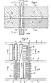
- the AM-AV drying areas each consist of a perforated sheet 1 carried by longitudinal beams forming rails 2 of circulation for the carriage and extended downwards by aprons to constitute supply and return air tunnels for drying.
- the sheets 1 are reinforced by crosspieces 3.
- the carriage frame and the rollers on the rails 2 as well as the drive means are not shown to simplify the drawings.
- the frame carries, by bearings 4-5, two parallel axes 6 and 7.
- the two axes are driven in the same direction shown by arrows in the figures.
- the front axis 6 carries a hedgehog whose teeth 8 come to tangent the surface of the perforated sheet 1 so as to pick up the forage lying in bed on the area and to project it, with the help of a guide plate 9 and deflecting teeth 10, on a conveyor belt 11 disposed transversely to the carriage and the upper strand of which flows from the area AM towards the area AV as represented by the arrow F 1 .
- a sheet 12 across the width of the AM area prevents the material from being projected beyond the conveyor.
- the rear axis 7 carries a hedgehog equalizing the bed, the teeth 13 of which are spaced from the sheet 1 of the thickness of the bed.
- a chute 14 Behind the sheet 12 and in front of the hedgehog 13 opens a chute 14 whose rear edge is extended by deflecting teeth 15 interposed between the teeth of the hedgehog 13.
- the chute 14 is located at the base of an enclosure 16 forming a reserve of spreadable fodder for a start of drying on the upstream area AM.
- a conveyor belt 17 At the bottom of the enclosure and over its entire width is mounted a conveyor belt 17 provided with teeth 17a which paint the base of the load and bring the material to the opening of the chute 14, the material being deflected towards the chute by deflecting teeth 18.
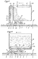
- the axis 6 carries the return cylinder 19 of a lifting belt 20 provided with projecting teeth 21.
- a deflecting plate 22 cooperates with the lifting belt 20 to prevent the dried material being found on the AV area and taken up by the teeth 21 of the lifting belt, falls back on said area.
- the material is projected by centrifugal force when the belt passes over the upper return cylinder 24 and it falls into an enclosure 25 intended to collect the dry material.
- Teeth 26 which engage between the teeth 21 of the lifting belt release the material which could stuff between said teeth.
- At the top of the tank 25 is mounted an endless belt 27 which can be driven in the direction of the arrow or lowered by jacks 28. The purpose of this conveyor belt is to spread the pile of material over the entire surface of the tank 25 and compact the material to reduce its volume.
- the shaft 7 carries a hedgehog whose teeth 30 pass over the upper surface of the sheet 1 at a distance equal to the thickness of the bed. Deflecting teeth 31 prevent the material from stuffing around the hedgehog 30.
- the enclosure 25 is empty and the enclosure 16 is loaded with material, for example fodder to be dried.
- material for example fodder to be dried.
- the truck is started.
- the fodder beds which were on the areas are picked up by the lifting belt 20-21 for the dry fodder located on the downstream area AV and by the hedgehog 8 for the semi-dried fodder found on the upstream area AM .
- the dry fodder raised by the lifting belt 20-21 is poured into the enclosure 25.
- the semi-dry fodder picked up by the hedgehog 8 is projected onto the conveyor belt 11 which brings it above the downstream area AV on which it is spread by the sheet 29 and the hedgehog 30, this area having been freed from the dry fodder treated during the preceding half-period by the lifting belt 20-21.
- the fodder to be dried being in the enclosure 16 is spread by the chute 14 and the hedgehog 13 on the upstream drying area AM which has been freed from the half-dried fodder during the preceding half-drying period by the hedgehog 8.
- the homologous sections are symmetrical with respect to a point P located between the areas equidistant from their ends. Namely, the fodder to be dried being supplied with M and the dry fodder discharged at S, the fodder supplied with M is deposited in a section a, 'which was released during the previous cycle and the semi-dried fodder is collected in the section a 2 'close to a i ' to be spread in section a 3 'released during the previous cycle, the dry fodder in section a; neighbor being picked up to be evacuated in S.
- the above embodiment of the method can be implemented with a trans device single carrier, pick-up and spreader, for example of the type described with reference to FIGS. 6 and 7, which moves on rails forming a circuit above the drying areas and the loading and unloading devices S.
- the meaning of forward movement is the direction of arrow C, FIG. 5.
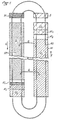
- the carriage comprises bogies 41 with rollers 42 some of which are motors which carry the frame 43. Under this frame hangs a transport platform 44 at a end of which is mounted the drum 45 of a pick-up 46 whose teeth pass between bars 47.
- the platform 44 is suspended from the frame, at the end corresponding to the pick-up, by fixed points 48 created by bars 49, fixed points around which levers 50 are articulated, one of the arms of which rotates the axis 51 of the pick-up while the other arm is actuated by a jack 52 acting between its end 53 and the frame 43 At its other end, platform 44 is suspended from the end 54 of a jack 55 articulated at 56 on the frame 43.
- the platform 44 can thus be raised, lowered and tilted longitudinally.
- a spreading hedgehog 57 is suspended by an oscillating bar 58 from the frame 43, the position of the hedgehog relative to the neighboring edge of the platform being adjustable by means of a jack 59.
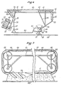
- the spreading and the equalization of the batch are ensured by a spreader designated as a whole by the reference 60 in FIG. 7.
- This spreader comprises a frame 61 secured to the arm 58 which carries four axes 62 on which pinions 63 are mounted, at least one of which is driven from the hedgehog axis 57; these sprockets guide two endless chains 64.
- On said endless chains are mounted regularly spaced axes 65 which carry flaps 66 directed towards the rear and capable of coming into abutment on the rear axis 65.
- the assembly is surrounded by a casing 67 which surrounds the two vertical strands and the upper strand of the chain, this casing being closed on its vertical face opposite to the hedgehog 57.
- the endless chains of the spreader device rotate in the direction of the arrow H so that the axis of articulation of the flaps 66 is located in front.
- the hedgehog 57 projects the fodder which is brought against it by sliding on the platform 44 suitably inclined by extension of the jack 52 and adjustment of the jack 59, above the lower strand of the chains without end 64 in the housing 67. If there is no bed formed on the perforated plate 68 on which the bed L is formed or if the thickness of the bed is small as illustrated in the left part of the figure 7, the flaps 66 hang freely and the projected fodder passes freely between them. When, on the other hand, the fodder bed rises, the flaps 66 gradually rise and brake then stop the passage of the fodder which is retained in bed F above the flaps. Detectors of any known type detect the raising position of all the flaps 66, which corresponds to a bed L formed over the entire width of the drying area 68, and control the advancement of the device.
- the device of FIG. 6 raised by lengthening the jack 52 and shortening the jack 55 so that it can circulate freely above the beds, is brought to station M where it receives, on the platform 44, a load of fodder corresponding to the quantity spread over an area a '.
- the device is then brought above the area a ' i , the pick-up 46 being, in the site plan adopted, in front of the device and the spreader device in the rear.
- the carriage In line with the downstream end of the area a ' i , the carriage is stopped, the spreading device is placed in a position of cooperation with the end of the platform 44 and the fodder is sent by the hedgehog 57 into the spreader 60.
- the carriage moves rearwards with respect to arrow C (Fig. 5) to spread its load over the entire area a ' 1 .
- the pick-up 47 is then brought to the right of the edge of the area a ′ 2 on which the partially dried fodder is located.
- the end of the platform 44 carrying the pick-up is lowered, this lowering being limited by stop rollers 69.
- the pick-up is then started and the device advances to scan the area at ' 2 and load the forage on this area onto platform 44.
- the load can be equalized by tilting, using the jacks, the loading platform.
- the loaded forage is then spread on section a ' 3 as described above for section a' 1 and the completely dry forage in section a ' 4 is loaded on platform 44 and unloaded in S to be evacuated.
- the device described with reference to Figures 6 and 7 can also be used in the case of a number of drying areas greater than two.
Landscapes
- Engineering & Computer Science (AREA)
- Mechanical Engineering (AREA)
- General Engineering & Computer Science (AREA)
- Life Sciences & Earth Sciences (AREA)
- Microbiology (AREA)
- Drying Of Solid Materials (AREA)
- Fodder In General (AREA)
- Apparatuses For Bulk Treatment Of Fruits And Vegetables And Apparatuses For Preparing Feeds (AREA)
- Processing Of Solid Wastes (AREA)
- Steroid Compounds (AREA)
Abstract
Description
La présente invention concerne le séchage de matières étalables en lit, notamment de fourrages, avec un flux d'air de débit important. Elle a plus spécialement pour objet de réduire le coût des équipements en autorisant l'installation du séchage dans des installations basses dans lesquelles les lits de séchage sont coplanaires.The present invention relates to the drying of spreadable materials in a bed, in particular fodder, with a large flow of air. It more specifically aims to reduce the cost of equipment by allowing the installation of drying in low installations in which the drying beds are coplanar.
On sait améliorer le rendement thermique d'un échangeur quelconque par le procédé dit à contre-courant. Une circulation à contre-courant des produits à sécher et des gaz de séchage réchauffés par passage sur un échangeur chaud a déjà été proposée par exemple pour des produits tels que des carreaux de plâtre dans le brevet français FR-A-2.304.045. Il s'agit toutefois dans le cas de produits massifs. Dans ce cas de produits étalables en lits tels que des produits fibreux ou granulaires ou des produits végétaux tels que les fourrages, il est bien connu que l'on obtient un séchage plus rapide si le flux d'air ou de gaz traverse la masse du produit, surtout si le produit est réparti en lits.It is known to improve the thermal efficiency of any exchanger by the so-called counter-current process. A counter-current circulation of the products to be dried and the drying gases heated by passage over a hot exchanger has already been proposed for example for products such as plaster tiles in French patent FR-A-2,304,045. However, these are massive products. In this case of products which can be spread out in beds such as fibrous or granular products or plant products such as fodder, it is well known that faster drying is obtained if the air or gas flow crosses the mass of the product, especially if the product is distributed in beds.
Pour associer les deux principes de séchage, à savoir le séchage par circulation à contre-courant et le séchage par traversée du lit de matière, on ne connaît à ce jour que le principe de la circulation du matériau disposé en lits sur des surfaces poreuses montées en série sur le trajet du flux du gaz de séchage. L'installation classique consiste à utiliser des tapis transporteurs perforés circulant en sens inverses, la matière à sécher étant amenée à l'extrémité amont d'un tapis transporteur et transférée à l'extrémité aval de celui-ci sur l'extrémité amont du tapis circulant en sens inverse, le flux gazeux traversant le tapis transporteur et le lit de matière qu'il porte. Le plus souvent les tapis transporteurs sont superposés et la matière tombe du tapis transporteur le plus élevé sur le transporteur immédiatement inférieur à l'extrémité aval de chaque tapis. Le degré de siccité de la matière croît au fur et à mesure qu'elle descend dans les étages. La matière est en déplacement pendant toute la durée du processus de séchage, le matériel de transport est complexe et coûteux et ce déplacement n'améliore pas l'efficacité de l'échange d'humidité entre la matière et le gaz de séchage.To associate the two drying principles, namely drying by counter-current circulation and drying by crossing the bed of material, we only know to date that the principle of the circulation of the material arranged in beds on porous surfaces mounted in series on the path of the drying gas flow. The conventional installation consists in using perforated conveyor belts circulating in opposite directions, the material to be dried being brought to the upstream end of a conveyor belt and transferred to the downstream end thereof on the upstream end of the carpet flowing in the opposite direction, the gas flow passing through the conveyor belt and the bed of material which it carries. Most often the conveyor belts are superimposed and the material falls from the highest conveyor belt onto the conveyor immediately below the downstream end of each conveyor belt. The degree of dryness of the material increases as it goes down in the stages. The material is in movement during the entire drying process, the transport equipment is complex and expensive and this movement does not improve the efficiency of the exchange of moisture between the material and the drying gas.
DE-A-3 006 126 décrit un dispositif de ce type dans lequel, pour pouvoir disposer des lits de matériau à sécher sur les deux brins de la chaîne, celle-ci est constituée par des volets qui sont libérés à l'extrémité de la chaîne proche d'un rouleau de renvoi pour laisser tomber le matériau porté par le volet qui s'ouvre sur l'autre brin de la même chaîne ou sur le brin supérieur de la chaîne placée en dessous.DE-A-3 006 126 describes a device of this type in which, in order to be able to have beds of material to be dried on the two strands of the chain, the latter consists of flaps which are released at the end of the chain close to a deflection roller to drop the material carried by the flap which opens on the other strand of the same chain or on the upper strand of the chain placed below.
On connaît également notamment par DE-A-2 209 013 une installation dans laquelle la matière est étalée sur une aire de séchage supérieure constituée par des volets et après un premier stade de séchage elle tombe sur l'aire de séchage située en dessous et ainsi de suite d'aire en aire, l'ensemble des aires de séchage étant traversé par un courant d'air de séchage ascendant. US-A-2050477 décrit une installation analogue, les aires superposées étant constituées chacune par une pluralité de plateaux oscillants avec lesquels coopèrent des moyens de balayage qui font, lors de chaque oscillation, tomber le matériau porté sur un plateau de l'aire située en dessous.Also known from DE-A-2 209 013 is an installation in which the material is spread on an upper drying area constituted by shutters and after a first drying stage it falls on the drying area situated below and thus immediately from area to area, all of the drying areas being traversed by an ascending stream of drying air. US-A-2050477 describes a similar installation, the superimposed areas each consisting of a plurality of oscillating plates with which cooperate scanning means which cause, during each oscillation, to drop the material carried on a plate of the area located in below.
Dès lors qu'il s'agit d'aires de séchage situées dans un même plan, on ne connaît comme installations comportant des aires de séchage fixes que des installations dans lesquelles on déplace la matière à sécher disposée en lit sur une aire perforée en utilisant un dispositif faneur qui se déplace au-dessus de l'aire de séchage, dispositif faneur qui peut être réalisé suivant le principe des rateaux faneurs ou constitué par un hérisson tournant en sens inverse de sa direction d'avancement. Dans ce type de séchoir le fourrage est, à chaque passage du dispositif faneur, déplacé selon la direction inverse de la progression de ce dispositif et retourné. Le dispositif qui pourrait être adapté à une pluralité d'aires de séchage pour réaliser un séchage à contre-courant est toutefois compliqué et aboutit à un retournement mécanique répété du fourrage, manipulation qui est consommatrice d'énergie et susceptible de provoquer une désagrégation de la matière.Since these are drying areas located in the same plane, only installations with fixed drying areas are known as installations in which the material to be dried is placed in a bed on a perforated area using a tedder device which moves above the drying area, tedder device which can be produced according to the principle of tedder rakes or constituted by a hedgehog rotating in opposite direction from its direction of advance. In this type of dryer the fodder is, with each passage of the tedder device, moved in the opposite direction of the progression of this device and returned. The device which could be adapted to a plurality of drying areas to carry out drying against the current is however complicated and results in repeated mechanical reversal of the fodder, a manipulation which consumes energy and is capable of causing disaggregation of the matter.
La présente invention a pour but de proposer une installation pour le séchage de matériaux étalables en lits perméables aux gaz, selon la méthode à contre-courant, qui réduit dans une forte mesure les investissements nécessaires pour la mise en oeuvre des procédés antérieurement connus dans lesquels on fait circuler, en continu ou pas à pas, pendant la durée du séchage, le matériau à sécher selon un parcours en zig-zag parallèlement à la plus grande dimension de la surface du lit et perpendiculairement à la direction d'écoulement du flux gazeux de séchage.The object of the present invention is to propose an installation for drying spreadable materials in gas-permeable beds, according to the counter-current method, which greatly reduces the investments necessary for the implementation of the previously known methods in which the material to be dried is circulated, continuously or step by step, during the drying period, in a zigzag course parallel to the largest dimension of the surface of the bed and perpendicular to the direction of flow of the gas flow drying.
L'installation pour le séchage de matières étalables en lits perméables aux gaz selon la méthode à contre-courant conformément à l'invention qui comporte une pluralité d'aires de séchage perforées disposées parallèlement les unes aux autres et en série selon le trajet de circulation du gaz de séchage de manière à ce qu'elles soient traversées successivement par le flux de gaz, avec des moyens pour amener la matière soumise au séchage sur l'aire amont qui se trouve la plus en aval dans le flux de gaz, et des moyens pour la transférer d'aire en aire, jusqu'à l'aire la plus en aval qui se trouve la plus en amont dans le flux de gaz d'où des moyens l'évacuent à l'état sec est caractérisée en ce que les aires de séchage perforées sont fixes et coplanaires et en ce que l'installation comporte des moyens pour amener la matière soumise au séchage sur l'aire amont la plus en aval dans le flux de gaz, moyens qui se déplacent au-dessus de ladite aire selon la plus grande direction des aires et déposent la matière à sécher dans des sections successives de ladite aire de séchage amont et des moyens pour le transfert d'aire en aire qui prélèvent la matière dans une section de l'aire amont et la transfèrent dans une section de l'aire aval dont la matière a été enlevée pour être transférée à l'aire plus en aval ou pour être évacuée.The installation for drying materials spreadable in gas-permeable beds according to the counter-current method according to the invention which comprises a plurality of perforated drying areas arranged parallel to each other and in series along the circulation path drying gas so that they pass successively through the gas flow, with means for bringing the material subjected to drying to the upstream area which is furthest downstream in the gas flow, and means for transferring it from area to area, up to the most downstream area which is furthest upstream in the gas flow from where means evacuate it in the dry state is characterized in that the perforated drying areas are fixed and coplanar and in that the installation includes means for bringing the material subjected to drying to the upstream area most downstream in the gas flow, means which move above said area in the greatest direction of the areas and deposit the material to be dried in successive sections of said upstream drying area and means for transfer from area to area which take the material in a section from the upstream area and transfer it to a section of the downstream area from which the material has been removed to be transferred to the area further downstream or to be evacuated.
Le transfert de la matière de l'aire amont à l'aire aval peut être réalisé par un premier châssis mobile selon la longueur de l'aire amont et portant un dispositif de ramassage ramassant sur la largeur de l'aire amont en avant du châssis et un dispositif d'étalement étalant la matière à sécher sur la largeur de l'aire amont en arrière du châssis et un second châssis mobile selon la longueur de l'aire aval et portant un dispositif de ramassage ramassant sur la largeur de l'aire aval en avant du second châssis et un dispositif d'étalement étalant la matière ramassée par le dispositif de ramassage de l'aire amont sur la largeur de l'aire aval en arrière du second châssis et des moyens pour transporter la matière ramassée par le dispositif de ramassage du premier châssis au dispositif d'étalement du second châssis.The transfer of the material from the upstream area to the downstream area can be achieved by a first movable chassis along the length of the upstream area and carrying a pickup device picking up across the width of the upstream area in front of the chassis and a spreading device spreading the material to be dried over the width of the upstream area behind the frame and a second frame movable along the length of the downstream area and carrying a pickup device picking up across the width of the area downstream in front of the second chassis and a spreading device spreading the material collected by the collecting device of the upstream area over the width of the downstream area behind the second chassis and means for transporting the material collected by the device of collecting the first chassis to the spreading device of the second chassis.
Dans le cas de deux aires de séchage disposées côte à côte dans un même plan et traversées par le flux gazeux l'une de bas en haut et l'autre de haut en bas pour laisser libre un tunnel supérieur recouvrant l'ensemble des deux aires, les deux châssis peuvent être réunis sous forme d'un chariot enjambant les deux aires et portant le moyen de transport disposé transversalement. Il est également possible de prévoir deux chariots indépendants se déplaçant selon des directions inverses au-dessus des aires en occupant des positions homologues, le moyen de transport étant constitué par des transporteurs parallèles aux aires avec un moyen de transfert de l'aire amont à l'aire aval situé en bout d'aire amont.In the case of two drying areas arranged side by side in the same plane and crossed by the gas flow, one from bottom to top and the other from top to bottom to leave free an upper tunnel covering all of the two areas , the two frames can be joined in the form of a carriage spanning the two areas and carrying the means of transport arranged transversely. It is also possible to provide two independent carriages moving in opposite directions over the areas while occupying homologous positions, the means of transport being constituted by conveyors parallel to the areas with a means of transfer from the upstream area to the downstream area located at the end of the upstream area.
La matière peut être amenée au dispositif d'étalement de l'aire amont et évacuée du dispositif de ramassage de l'aire aval par des bennes portées par le châssis mobile de l'aire amont et le châssis mobile de l'aire aval respectivement. Il est également possible de prévoir des transporteurs disposés parallèlement aux aires de séchage.The material can be brought to the device for spreading the upstream area and evacuated from the device for collecting the downstream area by skips carried by the movable frame of the upstream area and the movable frame of the downstream area respectively. It is also possible to provide conveyors arranged parallel to the drying areas.
Selon un autre mode de réalisation qui met à profit le fait que la matière à sécher n'est déplacée dans le procédé que par charges successives, la durée de transport d'une charge ne représentant qu'une très faible partie de la durée totale du séchage, la manutention et le transport de la matière à sécher sont assurés par un chariot unique se déplaçant sur des rails au-dessus des diverses aires de séchage, ce chariot comportant une plate-forme de chargement, des moyens de reprise susceptibles de reprendre le fourrage sur une surface pour le charger sur cette plate-forme et des moyens pour étaler le chargement de fourrage se trouvant sur cette plate-forme.According to another embodiment which takes advantage of the fact that the material to be dried is only displaced in the process by successive loads, the duration of transport of a load representing only a very small part of the total duration of the drying, handling and transport of the material to be dried are provided by a single carriage moving on rails above the various drying areas, this carriage comprising a loading platform, recovery means capable of taking up the fodder on a surface for loading it on this platform and means for spreading the loading of fodder being on this platform.
Les caractéristiques ci-dessus de la présente invention et d'autres caractéristiques de celle-ci seront mieux comprises à la lecture de la description de divers modes de réalisation possibles de la présente invention faite ci-après avec référence aux dessins ci-annexés dans lesquels :
- la figure 1 est une vue en plan schématique d'une installation de séchage à deux aires disposées côte à côte fonctionnant selon le procédé de l'invention ; N
- la figure 2 est une vue en plan schématique d'un mode de réalisation du chariot coopérant avec les aires de séchage ci-dessus ;
- la figure 3 est une vue en coupe schématique par III-III de figure 2 ;
- la figure 4 est une vue en coupe schématique par IV-IV de figure 2 ;
- la figure 5 est une vue en plan schématique d'une installation de séchage à deux aires côte à côte exploitée selon un autre mode de réalisation du procédé de l'invention ;
- la figure 6 est une vue en élévation latérale schématique d'un exemple de réalisation du chariot de manutention utilisé dans l'installation de figure 5 et
- la figure 7 est une vue en élévation à 90° de figure 6 du dispositif égalisateur du chariot de figure 6.
- Figure 1 is a schematic plan view of a drying system with two areas arranged side by side operating according to the method of the invention; NOT
- Figure 2 is a schematic plan view of an embodiment of the carriage cooperating with the above drying areas;
- Figure 3 is a schematic sectional view through III-III of Figure 2;
- Figure 4 is a schematic sectional view through IV-IV of Figure 2;
- FIG. 5 is a schematic plan view of a drying installation with two areas side by side operated according to another embodiment of the method of the invention;
- FIG. 6 is a schematic side elevation view of an exemplary embodiment of the handling trolley used in the installation of FIG. 5 and
- FIG. 7 is an elevation view at 90 ° of FIG. 6 of the leveling device of the carriage of FIG. 6.
Comme illustré schématiquement dans la figure 1, les deux aires de séchage constituées par une tôle perforée ou un treillis AV et AM sont disposées côte à côte et seules les parties de ces aires où est en cours le transfert de la matière à sécher ont été schématisées. L'aire AM est l'aire amont sur laquelle est la matière fraîche et l'aire AV est l'aire aval sur laquelle se termine le séchage. Le flux gazeux G, en pratique de l'air qui par exemple est réchauffé par passage sur l'échangeur chaud d'une pompe de chaleur, est amené sous l'aire AV et traverse de manière ascendante le lit de matière déjà débarrassée d'une partie de son humidité que porte cette aire puis il traverse de manière ascendante, comme schématisé par les flèches G, le lit de matière plus humide porté par l'aire amont AM pour être repris en dessous de cette aire.As illustrated schematically in FIG. 1, the two drying areas constituted by a perforated sheet or a mesh AV and AM are arranged side by side and only the parts of these areas where the transfer of the material to be dried is in progress have been schematized . The AM area is the upstream area on which the fresh material is and the AV area is the downstream area on which drying ends. The gas flow G, in practice air which, for example, is heated by passing over the hot exchanger of a heat pump, is brought under the AV area and ascends upwards the bed of material already rid of part of its humidity carried by this area then it crosses in an ascending manner, as shown schematically by the arrows G, the bed of more humid material carried by the upstream area AM to be taken up below this area.
RAM désigne le réservoir d'amenée de la matière à sécher et REV désigne le réservoir d'évacuation de la matière sèche dont un exemple sera décrit plus en détail ci-après mais qui pourraient être également des transporteurs continus tels que des tapis roulants transportant la matière dans le sens de la flèche F. Ces réservoirs ainsi que les moyens de distribution et de reprise sur les aires et de transfert d'aire à aire qui seront décrits schématiquement ci-après circulent dans le sens des flèches F. La matière à sécher amenée dans le réservoir RAM est répartie sur la section a1 pour constituer le lit A1 en arrière du dispositif. Le lit de matière A2 déjà à demi séchée et qui se trouve sur l'aire amont AM en avant du dispositif est repris sur la section a2 située en avant de a1 pour être transféré dans la section a3 de l'aire de séchage AV pour constituer le lit de matière A3 en arrière du dispositif et le lit de matière A4 à la siccité finale qui se trouve sur l'aire aval AV en avant du dispositif est repris pour être chargé dans le réservoir d'évacuation REV. Le réservoir d'amenée RAM est chargé en matière à sécher à l'extrémité amont des aires de séchage et la matière sèche est évacuée du réservoir REV à l'aval des aires de séchage. Les détails du dispositif peuvent varier selon la nature de la matière à sécher et on décrira plus particulièrement ci-après un dispositif adapté au séchage du fourrage.RAM designates the reservoir for supplying the material to be dried and REV designates the reservoir for discharging the dry material, an example of which will be described in more detail below but which could also be continuous conveyors such as conveyor belts transporting the material in the direction of arrow F. These tanks as well as the means of distribution and recovery on the areas and of transfer from area to area which will be described schematically below circulate in the direction of the arrows F. The material to be dried brought into the RAM tank is distributed over the section a 1 to constitute the bed A 1 behind the device. The bed of material A 2 already half dried and which is on the upstream area AM in front of the device is taken up in section a 2 located in front of a 1 to be transferred to section a 3 of the area of AV drying to constitute the bed of material A 3 behind the device and the bed of material A 4 at the final dryness which is on the downstream area AV in front of the device is taken up to be loaded into the REV drain tank. The RAM supply tank is loaded with material to be dried at the upstream end of the drying areas and the dry material is removed from the REV tank downstream from the drying areas. The details of the device may vary depending on the nature of the material to be dried and a device suitable for drying the fodder will be described more particularly below.
Les aires de séchage AM-AV sont constituées chacune par une tôle perforée 1 portée par des poutres longitudinales formant rails 2 de circulation pour le chariot et prolongées vers le bas par des tabliers pour constituer des tunnels de soufflage et de reprise de l'air de séchage. Les tôles 1 sont renforcées par des traverses 3.The AM-AV drying areas each consist of a perforated
Le bâti du chariot et les galets de roulement sur les rails 2 ainsi que les moyens d'entraînement ne sont pas représentés pour simplifier les dessins. Le bâti porte, par des paliers 4-5, deux axes parallèles 6 et 7. Les deux axes sont entraînés dans le même sens représenté par des flèches sur les figures.The carriage frame and the rollers on the
Au-dessus de l'aire amont AM, l'axe avant 6 porte un hérisson dont les dents 8 viennent tangenter la surface de la tôle perforée 1 de manière à ramasser le fourrage se trouvant en lit sur l'aire et à le projeter, avec l'aide d'une tôle de guidage 9 et de dents déflectrices 10, sur un tapis transporteur 11 disposé transversalement au chariot et dont le brin supérieur circule de l'aire AM vers l'aire AV comme représenté par la flèche F1. Une tôle 12 sur la largeur de l'aire AM empêche la matière d'être projetée au-delà du transporteur. Au-dessus de l'aire amont l'axe arrière 7 porte un hérisson égalisateur de lit dont les dents 13 sont espacées de la tôle 1 de l'épaisseur du lit. En arrière de la tôle 12 et en avant du hérisson 13 débouche une goulotte 14 dont le bord arrière se prolonge par des dents déflectrices 15 intercalées entre les dents du hérisson 13. La goulotte 14 est située à la base d'une enceinte 16 formant réserve de fourrage à étaler pour un début de séchage sur l'aire amont AM. Au fond de l'enceinte et sur toute sa largeur est monté un tapis transporteur 17 muni de dents 17a qui peignent la base de la charge et amènent la matière à l'ouverture de la goulotte 14, la matière étant déviée vers la goulotte par des dents déflectrices 18.Above the upstream area AM, the
Au-dessus de l'aire aval, l'axe 6 porte le cylindre de renvoi 19 d'un tapis élévateur 20 muni de dents en saillie 21. Une tôle déflectrice 22 coopère avec le tapis élévateur 20 pour empêcher que la matière séchée se trouvant sur l'aire AV et reprise par les dents 21 du tapis élévateur, retombe sur ladite aire. La matière est au contraire projetée par la force centrifuge au moment du passage du tapis sur le cylindre de renvoi supérieur 24 et elle tombe dans une enceinte 25 destinée à récolter la matière sèche. Des dents 26 qui s'engagent entre les dents 21 du tapis élévateur dégagent la matière qui pourrait bourrer entre lesdites dents. Au sommet de la cuve 25 est monté un tapis sans fin 27 qui peut être entraîné dans le sens de la flèche ou descendu par des vérins 28. Ce tapis transporteur a pour but d'étaler le tas de matière sur toute la surface de la cuve 25 et de tasser la matière pour réduire son volume.Above the downstream area, the
Au-dessus de la partie du brin supérieur du tapis transporteur 11 qui se trouve au-dessus de l'aire aval AV est disposée une tôle verticale en biais 29 qui repousse vers l'arrière la matière envoyée sur ce tapis par le hérisson 8 de l'aire amont AM de manière à répartir à peu près celle-ci sur la tôle perforée 1 de l'aire aval. Pour égaliser le lit, l'arbre 7 porte un hérisson dont les dents 30 passent au-dessus de la surface supérieure de la tôle 1 à une distance égale à l'épaisseur du lit. Des dents déflectrices 31 empêchent la matière de bourrer autour du hérisson 30.Above the part of the upper strand of the
Le fonctionnement du dispositif ci-dessus décrit avec référence aux figures 2 à 4 est le suivant.The operation of the device described above with reference to Figures 2 to 4 is as follows.
A l'extrémité amont des aires de séchage, à savoir vers la droite des figures, l'enceinte 25 est vide et l'enceinte 16 est chargée de matière par exemple de fourrage à sécher. A la fin d'une demi-période de séchage d'une durée égale à la moitié du temps de séchage où lorsque le fourrage se trouvant sur l'aire aval AV a atteint le taux d'humidité minimal correspondant au degré hygrométrique et à la température de l'air soufflé sous l'aire aval, le chariot est mis en route.At the upstream end of the drying areas, namely to the right of the figures, the
Les lits de fourrage qui se trouvaient sur les aires sont ramassés par le tapis élévateur 20-21 pour le fourrage sec se trouvant sur l'aire aval AV et par le hérisson 8 pour le fourrage à demi séché se trouvant sur l'aire amont AM. Le fourrage sec élevé par le tapis élévateur 20-21 est déversé dans l'enceinte 25. Le fourrage demi-sec ramassé par le hérisson 8 est projeté sur le tapis transporteur 11 qui l'amène au-dessus de l'aire aval AV sur laquelle il est étalé par la tôle 29 et le hérisson 30, cette aire ayant été débarrassée du fourrage sec traité pendant la demi-période précédente par le tapis élévateur 20-21.The fodder beds which were on the areas are picked up by the lifting belt 20-21 for the dry fodder located on the downstream area AV and by the
Le fourrage à sécher se trouvant dans l'enceinte 16 est étalé par la goulotte 14 et le hérisson 13 sur l'aire de séchage amont AM qui a été débarrassée du fourrage à demi séché au cours de la demi-période de séchage précédente par le hérisson 8.The fodder to be dried being in the
Dans le mode de réalisation de la figure 5, on retrouve les deux aires de séchage parallèles AM et AV qui sont traversées par le gaz de séchage selon les flèches G. Dans ce mode de réalisation, les sections homologues sont symétriques par rapport à un point P situé entre les aires à égale distance de leurs extrémités. A savoir le fourrage à sécher étant alimenté en M et le fourrage sec évacué en S, le fourrage alimenté en M est déposé dans une section a,' qui a été libérée lors du cycle précédent et le fourrage à demi-séché est ramassé dans la section a2' voisine de ai' pour être étalé dans la section a3' libérée au cours du cycle précédent, le fourrage sec dans la section a; voisine étant ramassé pour être évacué en S.In the embodiment of FIG. 5, there are the two parallel drying areas AM and AV which are crossed by the drying gas according to the arrows G. In this embodiment, the homologous sections are symmetrical with respect to a point P located between the areas equidistant from their ends. Namely, the fodder to be dried being supplied with M and the dry fodder discharged at S, the fodder supplied with M is deposited in a section a, 'which was released during the previous cycle and the semi-dried fodder is collected in the section a 2 'close to a i ' to be spread in section a 3 'released during the previous cycle, the dry fodder in section a; neighbor being picked up to be evacuated in S.
Le mode de réalisation ci-dessus du procédé peut être mis en oeuvre avec un dispositif transporteur, ramasseur et étaleur unique, par exemple du type décrit avec référence aux figures 6 et 7, qui se déplace sur des rails formant un circuit au-dessus des aires de séchage et des dispositifs de chargement M et de déchargement S. Le sens de circulation vers l'avant est le sens de la flèche C, figure 5. Le chariot comporte des boggies 41 avec des galets 42 dont certains sont moteurs qui portent le bâti 43. Sous ce bâti est suspendue une plate-forme de transport 44 à une extrémité de laquelle est monté le tambour 45 d'un pick-up 46 dont les dents passent entre des barreaux 47. La plate-forme 44 est suspendue au bâti, à l'extrémité correspondant au pick-up, par des points fixes 48 créés par des barres 49, points fixes autour desquels sont articulés des leviers 50 dont un des bras porte à rotation l'axe 51 du pick-up tandis que l'autre bras est actionné par un vérin 52 agissant entre son extrémité 53 et le bâti 43. A son autre extrémité, la plate-forme 44 est suspendue à l'extrémité 54 d'un vérin 55 articulé en 56 sur le bâti 43. La plate-forme 44 peut ainsi être soulevée, abaissée et inclinée longitudinalement.The above embodiment of the method can be implemented with a trans device single carrier, pick-up and spreader, for example of the type described with reference to FIGS. 6 and 7, which moves on rails forming a circuit above the drying areas and the loading and unloading devices S. The meaning of forward movement is the direction of arrow C, FIG. 5. The carriage comprises
Un hérisson d'épandage 57 est suspendu par une barre oscillante 58 au bâti 43, la position du hérisson par rapport au bord voisin de la plate-forme étant réglable grâce à un vérin 59. L'étalement et l'égalisation du lot sont assurés par un étaleur désigné dans son ensemble par la référence 60 à la figure 7. Cet étaleur comporte un bâti 61 solidaire du bras 58 lequel porte quatre axes 62 sur lesquels sont montés des pignons 63 dont au moins un est entraîné depuis l'axe du hérisson 57 ; ces pignons guident deux chaînes sans fin 64. Sur lesdites chaînes sans fin sont montés des axes 65 régulièrement espacés qui portent des volets 66 dirigés vers l'arrière et susceptibles de venir en butée sur l'axe 65 arrière. L'ensemble est entouré par un carter 67 qui entoure les deux brins verticaux et le brin supérieur de la chaîne, ce carter étant fermé sur sa face verticale opposée au hérisson 57. Les chaînes sans fin du dispositif étaleur tournent dans le sens de la flèche H pour que l'axe d'articulation des volets 66 soit situé en avant.A spreading
Le fonctionnement du dispositif étaleur est le suivant : le hérisson 57 projette le fourrage qui est amené contre lui en glissant sur la plate-forme 44 convenablement inclinée par allongement du vérin 52 et réglage du vérin 59, au-dessus du brin inférieur des chaînes sans fin 64 dans le carter 67. S'il n'y a pas de lit de formé sur la plaque perforée 68 sur laquelle est formé le lit L ou si l'épaisseur du lit est faible comme illustré dans la partie de gauche de la figure 7, les volets 66 pendent librement et le fourrage projeté passe librement entre eux. Lorsque, par contre, le lit de fourrage s'élève, les volets 66 remontent progressivement et freinent puis arrêtent le passage du fourrage qui est retenu en lit F au-dessus des volets. Des détecteurs d'un type quelconque connu détectent la position de relèvement de tous les volets 66, ce qui correspond à un lit L formé sur toute la largeur de l'aire de séchage 68, et commandent l'avancement du dispositif.The operation of the spreader device is as follows: the
Dans son utilisation dans le procédé de séchage schématisé à la figure 5, le dispositif de la figure 6 relevé par allongement du vérin 52 et raccourcissement du vérin 55 pour qu'il puisse circuler librement au-dessus des lits, est amené au poste M où il reçoit, sur la plate-forme 44, une charge de fourrage correspondant à la quantité étalée sur une aire a'. Le dispositif est alors amené au-dessus de l'aire a'i, le pick-up 46 étant, dans le schéma de chantier adopté, en avant du dispositif et le dispositif étaleur à l'arrière. Au droit de l'extrémité aval de l'aire a'i, le chariot est arrêté, le dispositif étaleur est placé en position de coopération avec l'extrémité de la plate-forme 44 et le fourrage est envoyé par le hérisson 57 dans l'étaleur 60. Le chariot se déplace vers l'arrière par rapport à la flèche C (Fig. 5) pour étaler son chargement sur toute l'aire a'1. Le pick-up 47 est alors amené au droit du bord de l'aire a'2 sur laquelle se trouve le fourrage partiellement séché. L'extrémité de la plate-forme 44 portant le pick-up est abaissée, cet abaissement étant limité par des roulettes de butée 69. Le pick-up est alors mis en route et le dispositif avance pour balayer l'aire a'2 et charger, sur la plate-forme 44, le fourrage se trouvant sur cette aire. Le chargement peut être égalisé en inclinant, à l'aide des vérins, la plate-forme de chargement. Le fourrage chargé est alors étalé sur la section a'3 de la manière décrite ci-dessus pour la section a'1 et le fourrage complètement sec se trouvant sur la section a'4 est chargé sur la plate-forme 44 et déchargé en S pour être évacué.In its use in the drying process shown diagrammatically in FIG. 5, the device of FIG. 6 raised by lengthening the
Le dispositif décrit avec référence aux figures 6 et 7 peut également être utilisé dans le cas d'un nombre d'aires de séchage supérieur à deux.The device described with reference to Figures 6 and 7 can also be used in the case of a number of drying areas greater than two.
Claims (5)
Priority Applications (1)
| Application Number | Priority Date | Filing Date | Title |
|---|---|---|---|
| AT83400921T ATE19300T1 (en) | 1982-05-10 | 1983-05-06 | DEVICE FOR DRYING RELEASED MATERIAL. |
Applications Claiming Priority (2)
| Application Number | Priority Date | Filing Date | Title |
|---|---|---|---|
| FR8208063 | 1982-05-10 | ||
| FR8208063A FR2526531B1 (en) | 1982-05-10 | 1982-05-10 | PROCESS FOR DRYING BED MATERIALS, ESPECIALLY FORAGE AND INSTALLATION FOR IMPLEMENTING SAME |
Publications (2)
| Publication Number | Publication Date |
|---|---|
| EP0094311A1 EP0094311A1 (en) | 1983-11-16 |
| EP0094311B1 true EP0094311B1 (en) | 1986-04-16 |
Family
ID=9273867
Family Applications (1)
| Application Number | Title | Priority Date | Filing Date |
|---|---|---|---|
| EP83400921A Expired EP0094311B1 (en) | 1982-05-10 | 1983-05-06 | Apparatus for drying spread materials |
Country Status (7)
| Country | Link |
|---|---|
| EP (1) | EP0094311B1 (en) |
| JP (1) | JPS5941770A (en) |
| AT (1) | ATE19300T1 (en) |
| CS (1) | CS251076B2 (en) |
| DE (1) | DE3363022D1 (en) |
| FR (1) | FR2526531B1 (en) |
| OA (1) | OA07424A (en) |
Families Citing this family (3)
| Publication number | Priority date | Publication date | Assignee | Title |
|---|---|---|---|---|
| GR1003348B (en) * | 1999-03-15 | 2000-03-29 | Unit for the dehydration of loose products | |
| CZ19179U1 (en) | 2008-10-23 | 2008-12-16 | Tarpo Spol. S R.O. | Equipment for continuous drying particulate materials |
| CN115978919B (en) * | 2022-12-30 | 2023-07-21 | 山东省国宠宠物食品有限责任公司 | Vacuum baking equipment for pet feed |
Family Cites Families (5)
| Publication number | Priority date | Publication date | Assignee | Title |
|---|---|---|---|---|
| US2050477A (en) * | 1935-03-15 | 1936-08-11 | Weisselberg Arnold | Method and apparatus for spreading divided material for treatment or other purposes |
| GB900384A (en) * | 1959-07-14 | 1962-07-04 | John Thompson Ind Const Ltd | Improvements in or relating to apparatus for the continuous treatment of finely divided materials |
| DE2209013A1 (en) * | 1972-02-25 | 1973-08-30 | Wolf Stahlbau Kg | HORD DRYERS |
| FR2336970A1 (en) * | 1975-12-30 | 1977-07-29 | Neu Sa | Silo for thermal or physicochemical grain treatments - with platforms made from motor-driven pivoting blades |
| DE3006126A1 (en) * | 1980-02-19 | 1981-09-03 | Heinz 6116 Eppertshausen Lindner | Harvested produce multiple stage dryer - has stacked conveyors with flaps permitting hot air circulation and discharge onto conveyor below |
-
1982
- 1982-05-10 FR FR8208063A patent/FR2526531B1/en not_active Expired
-
1983
- 1983-05-04 CS CS833149A patent/CS251076B2/en unknown
- 1983-05-06 EP EP83400921A patent/EP0094311B1/en not_active Expired
- 1983-05-06 DE DE8383400921T patent/DE3363022D1/en not_active Expired
- 1983-05-06 AT AT83400921T patent/ATE19300T1/en not_active IP Right Cessation
- 1983-05-10 JP JP58080271A patent/JPS5941770A/en active Pending
- 1983-05-10 OA OA57995A patent/OA07424A/en unknown
Also Published As
| Publication number | Publication date |
|---|---|
| CS251076B2 (en) | 1987-06-11 |
| ATE19300T1 (en) | 1986-05-15 |
| OA07424A (en) | 1984-11-30 |
| FR2526531A1 (en) | 1983-11-10 |
| DE3363022D1 (en) | 1986-05-22 |
| JPS5941770A (en) | 1984-03-08 |
| EP0094311A1 (en) | 1983-11-16 |
| CS314983A2 (en) | 1985-09-17 |
| FR2526531B1 (en) | 1987-03-20 |
Similar Documents
| Publication | Publication Date | Title |
|---|---|---|
| EP0709343B1 (en) | Furnace for continuously heating up glass-sheets to their bending and/or tempering temperature | |
| NL1030756C2 (en) | Device and method for transferring green bricks. | |
| EP0094311B1 (en) | Apparatus for drying spread materials | |
| EP0425397A1 (en) | Process for treatment by vermicomposting and apparatus therefor | |
| FR2924104A1 (en) | Food product bar e.g. ham bar, distribution system for e.g. specific slicing device, has conveying unit transporting bars towards device, and unit controlling distribution and conveying units according to respective criterion of bars | |
| EP1153253B1 (en) | Chamber and installation for drying animal waste | |
| FR2924202A1 (en) | INSTALLATION AND METHOD FOR STORING AND FEEDING A ROTARY OVEN | |
| EP0291464A1 (en) | Method and apparatus for aligning and/or orderly arranging products | |
| FR2695988A1 (en) | Modular three-stage drying of nuts - with recovery and recycling of heated air between drying silos | |
| EP0311530B1 (en) | Large scale shredder, especially for the textile industry | |
| EP0039627B1 (en) | Method and apparatus for erecting and forming packets of tiles or analogous products | |
| FR2517295A1 (en) | PROCESS AND PLANT FOR COOKING CERAMIC MATERIALS | |
| FR2695737A1 (en) | After-treatment apparatus for photopolymerizable printing plates. | |
| JPH05208709A (en) | Method and device to prepare fiber straw-bag consisting of cotton, synthetic fiber, etc. | |
| EP0732558B1 (en) | Apparatus for handling and circulating products in a dryer | |
| JP2002084972A (en) | Elevating conveyor for green tea manufacturing | |
| FR2654810A1 (en) | Device for loading and/or unloading the shelves of a freeze-drying tank | |
| JPH07216663A (en) | Method and apparatus for preparing fiber bale consisting of cotton, chemical fiber etc., in one line along fiber bale taking- out machine | |
| EP0121650B1 (en) | Hank dryer provided with rotating rods | |
| BE1001791A6 (en) | Systems for handling food products. | |
| US538413A (en) | Apparatus for loading or stacking lumber | |
| CN112161430A (en) | Capsule quick drying machine | |
| JPS626761B2 (en) | ||
| FR2601559A1 (en) | PROCESS FOR TRANSPORTING FOOD PASTES AND SIMILAR PRODUCTS, ESPECIALLY WITHIN A DRIER, AND APPARATUS FOR CARRYING OUT SAID METHOD | |
| FR2525874A3 (en) | Process and machine for stoning dried fruits esp. prunes - first rolls fruits into cylindrical form to load easily into conveyor pockets |
Legal Events
| Date | Code | Title | Description |
|---|---|---|---|
| PUAI | Public reference made under article 153(3) epc to a published international application that has entered the european phase |
Free format text: ORIGINAL CODE: 0009012 |
|
| AK | Designated contracting states |
Designated state(s): AT BE CH DE GB IT LI LU NL SE |
|
| 17P | Request for examination filed |
Effective date: 19840427 |
|
| GRAA | (expected) grant |
Free format text: ORIGINAL CODE: 0009210 |
|
| AK | Designated contracting states |
Kind code of ref document: B1 Designated state(s): AT BE CH DE GB IT LI LU NL SE |
|
| PG25 | Lapsed in a contracting state [announced via postgrant information from national office to epo] |
Ref country code: NL Effective date: 19860416 Ref country code: IT Free format text: LAPSE BECAUSE OF FAILURE TO SUBMIT A TRANSLATION OF THE DESCRIPTION OR TO PAY THE FEE WITHIN THE PRESCRIBED TIME-LIMIT;WARNING: LAPSES OF ITALIAN PATENTS WITH EFFECTIVE DATE BEFORE 2007 MAY HAVE OCCURRED AT ANY TIME BEFORE 2007. THE CORRECT EFFECTIVE DATE MAY BE DIFFERENT FROM THE ONE RECORDED. Effective date: 19860416 Ref country code: AT Effective date: 19860416 |
|
| REF | Corresponds to: |
Ref document number: 19300 Country of ref document: AT Date of ref document: 19860515 Kind code of ref document: T |
|
| PG25 | Lapsed in a contracting state [announced via postgrant information from national office to epo] |
Ref country code: SE Effective date: 19860430 |
|
| REF | Corresponds to: |
Ref document number: 3363022 Country of ref document: DE Date of ref document: 19860522 |
|
| PG25 | Lapsed in a contracting state [announced via postgrant information from national office to epo] |
Ref country code: LU Free format text: LAPSE BECAUSE OF NON-PAYMENT OF DUE FEES Effective date: 19860531 Ref country code: LI Effective date: 19860531 Ref country code: CH Effective date: 19860531 |
|
| NLV1 | Nl: lapsed or annulled due to failure to fulfill the requirements of art. 29p and 29m of the patents act | ||
| REG | Reference to a national code |
Ref country code: CH Ref legal event code: PL |
|
| PLBE | No opposition filed within time limit |
Free format text: ORIGINAL CODE: 0009261 |
|
| STAA | Information on the status of an ep patent application or granted ep patent |
Free format text: STATUS: NO OPPOSITION FILED WITHIN TIME LIMIT |
|
| 26N | No opposition filed | ||
| PGFP | Annual fee paid to national office [announced via postgrant information from national office to epo] |
Ref country code: DE Payment date: 19900504 Year of fee payment: 8 |
|
| PGFP | Annual fee paid to national office [announced via postgrant information from national office to epo] |
Ref country code: GB Payment date: 19900508 Year of fee payment: 8 |
|
| PGFP | Annual fee paid to national office [announced via postgrant information from national office to epo] |
Ref country code: BE Payment date: 19900518 Year of fee payment: 8 |
|
| PG25 | Lapsed in a contracting state [announced via postgrant information from national office to epo] |
Ref country code: GB Effective date: 19910506 |
|
| PG25 | Lapsed in a contracting state [announced via postgrant information from national office to epo] |
Ref country code: BE Effective date: 19910531 |
|
| BERE | Be: lapsed |
Owner name: CENTRE NATIONAL DU MACHINISME AGRICOLE DU GENIE R Effective date: 19910531 |
|
| GBPC | Gb: european patent ceased through non-payment of renewal fee | ||
| PG25 | Lapsed in a contracting state [announced via postgrant information from national office to epo] |
Ref country code: DE Effective date: 19920303 |