EP0090189A2 - Vorrichtung zum Abdichten einer Fuge - Google Patents
Vorrichtung zum Abdichten einer Fuge Download PDFInfo
- Publication number
- EP0090189A2 EP0090189A2 EP83101998A EP83101998A EP0090189A2 EP 0090189 A2 EP0090189 A2 EP 0090189A2 EP 83101998 A EP83101998 A EP 83101998A EP 83101998 A EP83101998 A EP 83101998A EP 0090189 A2 EP0090189 A2 EP 0090189A2
- Authority
- EP
- European Patent Office
- Prior art keywords
- parapet
- head piece
- covering
- sealing
- piece
- Prior art date
- Legal status (The legal status is an assumption and is not a legal conclusion. Google has not performed a legal analysis and makes no representation as to the accuracy of the status listed.)
- Granted
Links
- 238000007789 sealing Methods 0.000 title claims abstract description 21
- 230000032683 aging Effects 0.000 description 4
- 150000001875 compounds Chemical class 0.000 description 3
- XLYOFNOQVPJJNP-UHFFFAOYSA-N water Substances O XLYOFNOQVPJJNP-UHFFFAOYSA-N 0.000 description 3
- 239000000565 sealant Substances 0.000 description 2
- 230000006978 adaptation Effects 0.000 description 1
- 238000006243 chemical reaction Methods 0.000 description 1
- 230000005494 condensation Effects 0.000 description 1
- 238000009833 condensation Methods 0.000 description 1
- 238000010276 construction Methods 0.000 description 1
- 230000007797 corrosion Effects 0.000 description 1
- 238000005260 corrosion Methods 0.000 description 1
- 208000018459 dissociative disease Diseases 0.000 description 1
- 238000009415 formwork Methods 0.000 description 1
- 239000000463 material Substances 0.000 description 1
- 230000000149 penetrating effect Effects 0.000 description 1
- 229910001220 stainless steel Inorganic materials 0.000 description 1
- 239000010935 stainless steel Substances 0.000 description 1
Images
Classifications
-
- E—FIXED CONSTRUCTIONS
- E04—BUILDING
- E04D—ROOF COVERINGS; SKY-LIGHTS; GUTTERS; ROOF-WORKING TOOLS
- E04D13/00—Special arrangements or devices in connection with roof coverings; Protection against birds; Roof drainage ; Sky-lights
- E04D13/14—Junctions of roof sheathings to chimneys or other parts extending above the roof
- E04D13/1407—Junctions of roof sheathings to chimneys or other parts extending above the roof for flat roofs
- E04D13/1415—Junctions to walls extending above the perimeter of the roof
Definitions
- the invention relates to and presupposes, as is known, a device for sealing a vertical joint between parapet panels at the end of a flat roof or balcony covered with a waterproof covering, the covering being raised and fastened to the parapet panels.
- the joints between the parapet, roof and / or balcony slabs are completely closed.
- the changes in position or temperature-related changes in length of the adjacent components are transferred to the sealing compound.
- the known sealants have a limited lifespan of between 2 and 25 years. As a result, it is single Lich a question of time when the known joint seals lose their functionality. Severe structural damage is the result if the aged joint seals are not replaced regularly at certain intervals.
- the object of the invention is to create a simply constructed device for sealing a vertical joint between the parapet panels or parapets on the one hand and the roof or balcony panels on the other hand, which is resistant to aging and with which the joint can be kept open in order to cover trough-like roofs or balconies to serve as an emergency overflow.
- a two-part, telescopically extendable and shortenable sealing sheet is proposed, the head piece of which is angled inwards at the upper end and overlaps the upper edge of the covering and whose foot piece has angled edge strips on the vertical sides to the parapet to form an open gap , in which the head piece is guided, the edge strips engaging behind the head piece.
- the head piece can have a narrower upper part and a wider lower part, one between the upper part and the lower part Bend is arranged so that the lower part rests on the foot piece and the upper part lies in the same plane as the ends of the edge strips.
- a device designed according to the invention initially has the advantage of a very simple construction and, because of its divided embodiment, it can be adapted very easily to the differently high edged coverings of the roofs or balconies.
- the outstanding advantage of a device designed according to the invention is that it does not engage in the joint between the parapet panels and therefore, for example, temperature-related changes in length are also not transmitted to the sealing sheet.
- the open joint can also serve as an emergency overflow on trough-shaped roofs and balconies, making other auxiliary structures for the emergency overflow superfluous.
- a device designed according to the invention in that it can be produced from corrosion-resistant and aging-resistant materials, for example stainless steel sheets or also from plastic.
- a balcony slab 1 In front of a balcony slab 1 are two parapet slabs 2 and 3 at right angles, between which a joint 4 is formed.
- the balcony slab 1 is with a bituminous .
- Covering 5 covered, which is pulled up into a fold 6 of the two parapet panels 2, 3 and fastened there with a clamping rail 7.
- the surface of the covering 5 is covered with a plate covering 8.
- the joint 4 is sealed with a sealing sheet 9, which consists of a head piece 10 and a foot piece 11.
- the head piece 10 is angled inwards at the upper end and engages over the upper edge of the covering 5 or the clamping rail 7. In its upper part 10 a, the head piece 10 is somewhat narrower than in its lower part 10 b. The head piece 10 is slightly bent between the upper part 10a and lower part 10b.
- the foot piece 11 has on its long sides angled edge strips 12, between which the lower part 10b of the head piece 10 is guided. The ends of the edge strips 12 and the upper part 10a of the head piece 10 lie in the same plane. At the lower end, the foot piece 11 has an outwardly angled drip ledge 13.
- the sealing sheet 9 is set up together with the parapet slabs 2 and then cast in with the balcony slab 1.
Landscapes
- Engineering & Computer Science (AREA)
- Architecture (AREA)
- Civil Engineering (AREA)
- Structural Engineering (AREA)
- Building Environments (AREA)
- Cable Accessories (AREA)
Abstract
Description
- Die Erfindung betrifft und setzt als bekannt voraus eine Vorrichtung zum Abdichten einer senkrechten Fuge zwischen Brüstungsplatten am Abschluß eines mit einem wasserdichten Belag eingedeckten flachen Daches oder Balkones, wobei der Belag an den Brüstungsplatten hochgeführt und befestigt ist.
- Die Abdichtung von Außenfugen zwischen Brüstungsplatten oder Attiken und Dächern bzw. Balkonen erfolgt zur Zeit mit in kaltem Zustand verarbeitbaren, in pastöser Form spritzbaren Massen, die durch chemische Reaktion zu dauerelastischen, alterungsbeständigen Dichtungsstoffen aushärten. Diese Abdichtungsform gemäß DIN 18540 entspricht dem Stand der Technik.
- Mit den bekannten Dichtungsmassen werden die Fugen zwischen den Brüstungs-, Dach- und/oder Balkonplatten vollständig geschlossen. Die Lageveränderungen oder-temperaturbedingte Längenänderungen der angrenzenden Bauteile werden auf die Dichtungsmasse übertragen. Die bekannten Dichtungsmassen haben eine zeitlich begrenzte Lebensdauer zwischen 2 und 25 Jahren. Infolgedessen ist es lediglich eine Frage der Zeit, wann die bekannten Fugendichtungen ihre Funktionsfähigkeit verlieren. Schwere Bauschäden sind die Folge, wenn die gealterten Fugendichtungen nicht regelmäßig in bestimmten Zeitabständen erneuert werden.
- Aus der US-PS 40 24 681 ist ein System zum Abdichten einer senkrechten Fuge mit einem eine Schlaufenform aufweisenden Teil eines an Brüstungsplatten hochgeführten, wasserdichten Belages bekannt. Dieses System ist verhältnismäßig aufwendig und wenig alterungsbeständig.
- Davon ausgehend liegt der Erfindung die Aufgabezugrunde, eine einfach konstruierte Vorrichtung zum Abdichten einer senkrechten Fuge zwischen den Brüstungsplatten bzw. Attiken einerseits und den Dach- oder Balkonplatten andererseits zu schaffen, die alterungsbeständig ist und mit der die Fuge offengehalten werden kann, um bei trogartigen Dächern oder Balkonen als Notüberlauf zu dienen.
- Zur Lösung dieser Aufgabe wird ein zweiteiliges, teleskopartig verlänger- und verkürzbares Dichtungsblech vorgeschlagen, dessen Kopfstück am oberen Ende nach innen abgewinkelt ist und den oberen Rand des Belages übergreift und dessen Fußstück an den senkrechten Seiten zur Brüstung hin abgewinkelte Randstreifen zur Bildung eines offenen Spaltes besitzt, in dem das Kopfstück geführt ist, wobei die Randstreifen das Kopfstück hintergreifen.
- Bei einer praktischen Ausführungsform kann das Kopfstück ein schmaleres Oberteil und ein breiteres Unterteil besitzen, wobei zwischen Oberteil und Unterteil eine Abkröpfung angeordnet ist, damit das Unterteil dem Fußstück anliegt und das Oberteil in der gleichen Ebene wie die Enden der Randstreifen liegt. Außerdem hat es sich noch als zweckmäßig erwiesen, am unteren Ende des Fußstückes eine nach außen abgewinkelte Tropfleiste anzuordnen.
- Eine erfindungsgemäß ausgebildete Vorrichtung hat zunächst den Vorteil eines sehr einfach konstruktiven Aufbaues und kann wegen ihrer geteilten Ausführungsform sehr einfach an die unterschiedlich hoch aufgekanteten Beläge der Dächer bzw. Balkone angepaßt werden. Der herausragende Vorteil einer erfindungsgemäß ausgebildeten Vorrichtung besteht jedoch darin, daß sie nicht in die Fuge zwischen den Brüstungsplatten eingreift und deshalb beispielsweise temperaturbedingte Längenänderungen auch nicht auf das Dichtungsblech übertragen werden. Die offene Fuge kann gleichzeitig bei trogartig ausgebildeten Dächern und Balkonen als Notüberlauf dienen und macht damit andere Hilfskonstruktionen für den Notüberlauf überflüssig. Schließlich besteht noch ein besonderer Vorteil einer erfindungsgemäß ausgebildeten Vorrichtung darin, daß sie aus korrosionsfesten und alterungsbeständigen Materialien, beispielsweise Edelstahlblechen oder auch aus Kunststoff hergestellt werden kann.
- Weitere Einzelheiten des Gegenstandes der Erfindung ergeben sich aus der nachfolgenden Beschreibung der zugehörigen Zeichnungen, in denen eine bevorzugte Ausführungsform einer erfindungsgemäß ausgebildeten Vorrichtung schematisch dargestellt worden ist. In deri Zeichnungen zeigen:
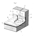
- Fig. 1 einen Abschnitt einer Balkonbrüstung in perspektivischer Darstellung;
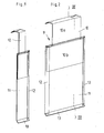
- Fig. 2 ein Dichtungsblech in perspektivischer Darstellung;
- Fig. 3 dasselbe Dichtungsblech entlang der Linie A-A in Fig. 2 geschnitten.
- Vor einer Balkonplatte 1 stehen im rechten Winkel zwei Brüstungsplatten 2 und 3, zwischen denen eine Fuge 4 gebildet wird. Die Balkonplatte 1 ist mit einem bituminösen.Belag 5 abgedeckt, der in einen Falz 6 der beiden Brüstungsplatten 2, 3 hochgezogen und dort mit einer Klemmschiene 7 befestigt ist. Die Oberfläche des Belages 5 ist mit einem Plattenbelag 8 abgedeckt.
- Die Fuge 4 ist mit einem Dichtungsblech 9 abgedichtet, welches aus einem Kopfstück 10 und einem Fußstück 11 besteht.
- Das Kopfstück 10 ist am oberen Ende nach innen abgewinkelt und übergreift den oberen Rand des Belages 5 bzw. die Klemmschiene 7. In seinem Oberteil 10a ist das Kopfstück 10 etwas schmaler als in seinem Unterteil 10b. Zwischen dem Oberteil 10a und Unterteil 10 b ist das Kopfstück 10 leicht abgekröpft.
- Das Fußstück 11 besitzt an seinen Längsseiten nach außen abgewinkelte Randstreifen 12, zwischen denen das Unterteil 10b des Kopfstückes 10 geführt ist. Die Enden der Randstreifen 12 und das Oberteil 10a des Kopfstückes 10 liegen in der gleichen Ebene. Am unteren Ende besitzt das Fußstück 11 eine nach außen abgewinkelte Tropfleiste 13.
- Infolge der zweiteiligen Ausführung des Dichtungsbleches 9 ist eine einfache Anpassung an die unterschiedlich hohen Falze 6 bzw. unterschiedlich dicken Balkonplatten 1 möglich. Von außen in die Fuge 4 eindringendes Wasser wird vom Dichtungsblech aufgefangen und nach unten über die Tropfleiste 13 abgeleitet, ohne in den Spalt zwischen dem Belag 5 einerseits und der Balkonplatte 1 bzw. den Brüstungsplatten 2, 3 andererseits eindringen zu können. Auch Schwitzwasser, welches sich im Bereich des Dichtungsbleches 9 bilden sollte, wird von diesem nach unten über die Tropfleiste 13 abgeleitet. Die an den Brüstungsplatten 2, 3 sich abstützenden Randstreifen 12 sorgen dafür, daß immer ein ausreichender Luftspalt vorhanden ist, um Wasser und Feuchtigkeit abzuleiten.
- Das Dichtungsblech 9 wird nach dem Erstellen der Schalung für die Balkonplatte 1 zusammen mit den Brüstungsplatten 2 aufgestellt und dann mit der Balkonplatte 1 eingegossen.
-
- 1 Balkonplatte
- 2 Brüstungsplatte
- 3 Brüstungsplatte
- 4 Fuge
- 5 Belag
- 6 Falz
- 7 Klemmschiene
- 8 Plattenbelag
- 9 Dichtungsblech
- 10 Kopfstück
- 10a Oberteil
- 10b Unterteil
- 11 Fußstück
- 12 Randstreifen
- 13 Tropfleiste
Claims (4)
Priority Applications (1)
| Application Number | Priority Date | Filing Date | Title |
|---|---|---|---|
| AT83101998T ATE19118T1 (de) | 1982-03-29 | 1983-03-02 | Vorrichtung zum abdichten einer fuge. |
Applications Claiming Priority (2)
| Application Number | Priority Date | Filing Date | Title |
|---|---|---|---|
| DE3211505 | 1982-03-29 | ||
| DE3211505A DE3211505C1 (de) | 1982-03-29 | 1982-03-29 | Vorrichtung zum Abdichten einer Fuge |
Publications (3)
| Publication Number | Publication Date |
|---|---|
| EP0090189A2 true EP0090189A2 (de) | 1983-10-05 |
| EP0090189A3 EP0090189A3 (en) | 1984-09-05 |
| EP0090189B1 EP0090189B1 (de) | 1986-04-09 |
Family
ID=6159593
Family Applications (1)
| Application Number | Title | Priority Date | Filing Date |
|---|---|---|---|
| EP83101998A Expired EP0090189B1 (de) | 1982-03-29 | 1983-03-02 | Vorrichtung zum Abdichten einer Fuge |
Country Status (3)
| Country | Link |
|---|---|
| EP (1) | EP0090189B1 (de) |
| AT (1) | ATE19118T1 (de) |
| DE (1) | DE3211505C1 (de) |
Family Cites Families (1)
| Publication number | Priority date | Publication date | Assignee | Title |
|---|---|---|---|---|
| US4024681A (en) * | 1976-06-17 | 1977-05-24 | Tremco Incorporated | Flashing system |
-
1982
- 1982-03-29 DE DE3211505A patent/DE3211505C1/de not_active Expired
-
1983
- 1983-03-02 AT AT83101998T patent/ATE19118T1/de not_active IP Right Cessation
- 1983-03-02 EP EP83101998A patent/EP0090189B1/de not_active Expired
Also Published As
| Publication number | Publication date |
|---|---|
| DE3211505C1 (de) | 1983-10-06 |
| EP0090189B1 (de) | 1986-04-09 |
| EP0090189A3 (en) | 1984-09-05 |
| ATE19118T1 (de) | 1986-04-15 |
Similar Documents
| Publication | Publication Date | Title |
|---|---|---|
| DE2142733C3 (de) | Eindeckrahmen für in der Dachfläche liegende Dachfenster | |
| EP0090189B1 (de) | Vorrichtung zum Abdichten einer Fuge | |
| DE2112355B2 (de) | Vorrichtung zum Anschließen einer wasserdichten Dichtungsbahn an der senkrechten Wand eines Bauwerkes | |
| DE2856835B2 (de) | Aufsatzkranz für Dachfenster o.dgl. | |
| EP0127071A2 (de) | Dachabdeckungsstein | |
| DE2610398A1 (de) | Schiebedach zur ueberdachung von terrassen und aehnlichen flaechen | |
| DE19729309A1 (de) | Vorrichtung zur Befestigung von kastenförmigen Einrichtungen | |
| DE8804855U1 (de) | Wärmedämmplattenkonstruktion, insbesondere für Schrägdächer | |
| DE3416208A1 (de) | Blumentrog fuer daecher von gebaeuden und dachabdeckungsstein hierfuer | |
| DE4343964A1 (de) | Gebäudekonstruktion als Glasfassade oder Glasdach | |
| DE2650400A1 (de) | Dachpfanne mit angesetztem dachrinnenstueck | |
| DE2162274A1 (de) | Bedachung mit geneigten rechteckigen fluegeln und vorgefertigte abdeckelemente zur herstellung der bedachung | |
| DE1509088C (de) | Dachoberlicht | |
| DE29510106U1 (de) | Vorrichtung zur Dacheinbindung von Dachkollektoren | |
| DE2745845A1 (de) | Bausatz zur herstellung einer dachdaemmung | |
| DE4441712C2 (de) | Bauelementensatz für einen Dachaufbau | |
| DE1609654C (de) | Ortgangverkleidung fur Flachdacher Ausscheidung aus 1255277 | |
| DE9114556U1 (de) | Eindeckrahmen | |
| DE29604745U1 (de) | Profilschiene | |
| DE29511065U1 (de) | Abschlußprofil für Gebäudeteile | |
| DE2306963C3 (de) | Fugenabdichtung | |
| DE20101489U1 (de) | Fassadenverkleidung | |
| DE1509073C (de) | Dacheindeckungsplatte | |
| DE1295790B (de) | Regenabtropfschiene fuer den oberen Aussenrand einer Wandoeffnung fuer Fenster | |
| DE2413822B2 (de) | Vorrichtung zum abdecken von etwa horizontalen dehnungsfugen in bauwerken |
Legal Events
| Date | Code | Title | Description |
|---|---|---|---|
| PUAI | Public reference made under article 153(3) epc to a published international application that has entered the european phase |
Free format text: ORIGINAL CODE: 0009012 |
|
| AK | Designated contracting states |
Designated state(s): AT BE CH FR GB IT LI NL SE |
|
| PUAL | Search report despatched |
Free format text: ORIGINAL CODE: 0009013 |
|
| AK | Designated contracting states |
Designated state(s): AT BE CH FR GB IT LI NL SE |
|
| 17P | Request for examination filed |
Effective date: 19841224 |
|
| GRAA | (expected) grant |
Free format text: ORIGINAL CODE: 0009210 |
|
| AK | Designated contracting states |
Kind code of ref document: B1 Designated state(s): AT BE CH FR GB IT LI NL SE |
|
| REF | Corresponds to: |
Ref document number: 19118 Country of ref document: AT Date of ref document: 19860415 Kind code of ref document: T |
|
| ET | Fr: translation filed | ||
| ITF | It: translation for a ep patent filed | ||
| PLBE | No opposition filed within time limit |
Free format text: ORIGINAL CODE: 0009261 |
|
| STAA | Information on the status of an ep patent application or granted ep patent |
Free format text: STATUS: NO OPPOSITION FILED WITHIN TIME LIMIT |
|
| 26N | No opposition filed | ||
| PGFP | Annual fee paid to national office [announced via postgrant information from national office to epo] |
Ref country code: GB Payment date: 19890228 Year of fee payment: 7 |
|
| PGFP | Annual fee paid to national office [announced via postgrant information from national office to epo] |
Ref country code: FR Payment date: 19890315 Year of fee payment: 7 |
|
| PGFP | Annual fee paid to national office [announced via postgrant information from national office to epo] |
Ref country code: SE Payment date: 19890322 Year of fee payment: 7 |
|
| PGFP | Annual fee paid to national office [announced via postgrant information from national office to epo] |
Ref country code: AT Payment date: 19890324 Year of fee payment: 7 |
|
| ITTA | It: last paid annual fee | ||
| PGFP | Annual fee paid to national office [announced via postgrant information from national office to epo] |
Ref country code: NL Payment date: 19890331 Year of fee payment: 7 |
|
| PGFP | Annual fee paid to national office [announced via postgrant information from national office to epo] |
Ref country code: BE Payment date: 19890509 Year of fee payment: 7 |
|
| PGFP | Annual fee paid to national office [announced via postgrant information from national office to epo] |
Ref country code: CH Payment date: 19890608 Year of fee payment: 7 |
|
| PG25 | Lapsed in a contracting state [announced via postgrant information from national office to epo] |
Ref country code: GB Effective date: 19900302 Ref country code: AT Effective date: 19900302 |
|
| PG25 | Lapsed in a contracting state [announced via postgrant information from national office to epo] |
Ref country code: SE Effective date: 19900303 |
|
| PG25 | Lapsed in a contracting state [announced via postgrant information from national office to epo] |
Ref country code: LI Effective date: 19900331 Ref country code: CH Effective date: 19900331 Ref country code: BE Effective date: 19900331 |
|
| BERE | Be: lapsed |
Owner name: EMIL BAST BAUUNTERNEHEMEN Effective date: 19900331 |
|
| PG25 | Lapsed in a contracting state [announced via postgrant information from national office to epo] |
Ref country code: NL Effective date: 19901001 |
|
| GBPC | Gb: european patent ceased through non-payment of renewal fee | ||
| NLV4 | Nl: lapsed or anulled due to non-payment of the annual fee | ||
| PG25 | Lapsed in a contracting state [announced via postgrant information from national office to epo] |
Ref country code: FR Effective date: 19901130 |
|
| REG | Reference to a national code |
Ref country code: CH Ref legal event code: PL |
|
| REG | Reference to a national code |
Ref country code: FR Ref legal event code: ST |
|
| EUG | Se: european patent has lapsed |
Ref document number: 83101998.9 Effective date: 19910110 |