EP0088233A2 - Handbandschleifer - Google Patents
Handbandschleifer Download PDFInfo
- Publication number
- EP0088233A2 EP0088233A2 EP83100996A EP83100996A EP0088233A2 EP 0088233 A2 EP0088233 A2 EP 0088233A2 EP 83100996 A EP83100996 A EP 83100996A EP 83100996 A EP83100996 A EP 83100996A EP 0088233 A2 EP0088233 A2 EP 0088233A2
- Authority
- EP
- European Patent Office
- Prior art keywords
- belt
- drive unit
- dust bag
- hand
- belt sander
- Prior art date
- Legal status (The legal status is an assumption and is not a legal conclusion. Google has not performed a legal analysis and makes no representation as to the accuracy of the status listed.)
- Granted
Links
Images

Classifications
-
- B—PERFORMING OPERATIONS; TRANSPORTING
- B24—GRINDING; POLISHING
- B24B—MACHINES, DEVICES, OR PROCESSES FOR GRINDING OR POLISHING; DRESSING OR CONDITIONING OF ABRADING SURFACES; FEEDING OF GRINDING, POLISHING, OR LAPPING AGENTS
- B24B55/00—Safety devices for grinding or polishing machines; Accessories fitted to grinding or polishing machines for keeping tools or parts of the machine in good working condition
- B24B55/06—Dust extraction equipment on grinding or polishing machines
- B24B55/10—Dust extraction equipment on grinding or polishing machines specially designed for portable grinding machines, e.g. hand-guided
- B24B55/107—Dust extraction equipment on grinding or polishing machines specially designed for portable grinding machines, e.g. hand-guided with belt-like tools
Definitions
- the invention relates to a hand belt sander with an endless sanding belt guided over two deflection rollers and a pressure shoe and with a drive unit arranged above the sanding belt with a handle, as well as with a blower for dust extraction and a suction channel with a blow-out opening that can be covered by a dust bag.
- Hand belt grinders of this type are known.
- the drive unit in which the drive unit is generally arranged approximately in the middle of the sanding belt underneath, the outlet opening of the suction channel must be guided to the side so that the dust bag can be attached.
- the invention has for its object to design a hand belt grinder so that these disadvantages are avoided and, above all, that the dust bag no longer obstructs.
- the invention consists in a hand-held belt sander of the type mentioned at the outset that the drive unit is laid in the region of the front deflection roller and that the blow-out opening is arranged approximately above this front deflection roller and is open towards the front.
- This configuration has the great advantage that the dust bag can no longer be arranged laterally but in front of the drive unit, so that this enables a very narrow design and also prevents obstruction of handling and a lateral view of the edges of the sanding belt.
- the holder for the dust bag is attached to a holding flange at the blow-out opening and if this dust bag holder has a protective strip covering the uncovered sanding belt in the region of the front deflection roller.
- the invention initially has the advantage that a separate protective hood for the sanding belt in the front area is no longer necessary due to the forwardly displaced arrangement of the drive unit. This task can take over the dust bag holder in the subject of the invention. If this is removed, then the advantage is also achieved that in front of the drive unit in an area that is not readily accessible to the hands of the operator, there is a free abrasive belt surface that can be used, for example, for grinding grooves. Such a possible application did not exist in the known hand-held loop. It is only necessary to remove the holder for the dust bag and this itself. After attaching the dust bag and its holder, the front area is covered securely.
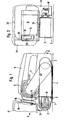
- a rotating grinding belt 1 is guided by two deflecting rollers 2 and 3, of which the rear deflecting roller 3 is driven.
- Both deflection rollers and a pressure shoe 4, which presses the lower run of the grinding belt 1 down over the region of the deflection rollers 2 and 3, are arranged in a guide housing for the hand-held sander, which has an upwardly projecting handle 5, which is approximately in the longitudinal center plane of the grinding belt 2.
- a drive unit 6 in the form of an electric motor is arranged offset in the front area of the grinding belt 1, so that the front boundary of this drive unit 6 extends into the area above the deflection roller 2.
- the sanding belt 1 is not covered in the area in front of the drive unit 6 by the housing of the hand belt sander, so that the guide parts 10 for receiving the bearing of the front deflection roller 2 and the sanding belt 1 protrude via the side cover, which is indicated with the front boundary 9 .
- a drive belt runs from the motor 6 within the housing cover 11 which projects laterally in this area (FIG. 2) and leads to a gear wheel which is then operatively connected to the deflection roller 3 in a manner not shown in detail.
- the drive from the drive unit 6 to the grinding belt is of a known type.
- the mouth 14 On the front of the drive unit 6 above the front deflection roller 2 there is the mouth 14 of a suction channel, starting in a known manner, from the upper run of the grinding belt 1 for the dust arising during processing, which is suctioned off from there via a fan connected to the electric motor and for Mouth 14 is promoted.
- the mouth 14 has a flange 15 over which a clamping bracket 16 for a dust bag 17 is pushed.
- a holder 18 To hold the dust bag 17 lying transversely in front of the hand-held belt sander, a holder 18 is provided which starts from the clamp holder 16 which is pushed over the flange 15 designed as a guide.
- the holder 18 consists of one piece with the clamping holder 16, which forms a U-shaped guide with slightly conically diverging legs. The two legs are pushed over the appropriately designed flange 15 and thus secure the hold of the clamping bracket 16 with the bracket 18.
- the bracket 18 has an upwardly extending web part 20 which merges into a transverse bracket 22 holding the dust bag 17 above.
- the holder 18 On its underside, the holder 18 has a protective strip 19 which extends over the otherwise open front area of the grinding belt 1 and over the front deflection roller 2.
- the protective strip 19 covers the front area of the processing and with the holder 18 attached Abrasive belt. After removal of the holder 18, it is also possible - as shown in FIGS. 3 and 4 - to machine fillets 23 with the front part 1 a of the belt 1. This can be carried out particularly cheaply - as shown in FIGS. 3 and 4 - if the hand belt sander is turned with its abrasive belt surface upwards and is fixed stationary with an auxiliary holder 24, for example on a table 25. Of course, grooves can also be processed in the normal working position with the hand belt sander. So far this has not been possible.
- the new hand-held belt sander can be used as a one-hand sander.
- the operator's hand presses against the active grinding surface due to the overall design.
- the motor weight and the hand pressure result in an ideal pressure for the grinding process.
- the handle 5 runs approximately at the height of the upper edge of the drive unit 6 to the rear, so that a flat design is also possible, which allows an attack relatively close to the grinding belt. This also makes handling much easier.
Abstract
Description
- Die Erfindung betrifft einen Handbandschleifer mit einem über zwei Umlenkrollen und einen Druckschuh geführten endlosen Schleifband und mit einem oberhalb des Schleifbandes angeordneten Antriebsaggregat mit einem Handgriff, sowie mit einem Gebläse zur Staubabsaugung und einem Absaugkanal mit einer durch einen Staubsack abdeckbaren Ausblasöffnung.
- Handbandschleifer dieser Art sind bekannt. Die Ausblasöffnung des Absaugkanales muß bei diesen bekannten Bauarten, bei denen das Antriebsaggregat in der Regel etwa in der Mitte des darunterliegenden Schleifbandes angeordnet ist, nach der Seite geführt werden, damit der Staubsack angebracht werden kann.
- Solche Bauarten weisen daher den Nachteil auf, daß der Staubsack bei der Bearbeitung teilweise hinderlich ist. Es wird auch notwendig, eine über das Antriebsaggregat nach vorne und hinten hinausragende Abdeckung für das Schleifband vorzusehen, die zwar zum Schutz für die Bedienungsperson dient, andererseits aber gewisse Bearbeitungsvorgänge nur zuläßt, wenn der Handbandschleifer stationär aufgestellt wird, so daß die Schleifbandunterseite zugängig ist.
- Der Erfindung liegt die Aufgabe zugrunde, einen Handbandschleifer so auszubilden, daß diese Nachteile vermieden sind und daß vor allen Dingen eine Behinderung durch den Staubsack nicht mehr auftritt.
- Die Erfindung besteht bei einem Handbandschleifer der eingangs genannten Art darin, daß das Antriebsaggregat in den Bereich der vorderen Umlenkrolle verlegt ist und daß die Ausblasöffnung etwa oberhalb dieser vorderen Umlenkrolle angeordnet und nach vorne offen ist. Diese Ausgestaltung weist den großen Vorteil auf, daß der Staubsack nicht mehr seitlich sondern.vor dem Antriebsaggregat angeordnet werden kann, so daß dadurch eine sehr schmale Bauweise ermöglicht wird und außerdem eine Behinderung der Handhabung und der seitlichen Sicht auf die Schleifbandkanten nicht mehr eintritt.
- Besonders vorteilhaft ist es, wenn die Halterung für den Staubsack an einem Halteflansch an der Ausblasöffnung aufgesteckt ist und wenn diese Staubsackhalterung eine das unabgedeckte Schleifband im Bereich der vorderen Umlenkrolle überdeckende Schutzleiste aufweist. Die Erfindung bringt nämlich zunächst den Vorteil mit sich, daß durch die nach vorne versetzte Anordnung des Antriebsaggregates eine gesonderte Schutzhaube für das Schleifband im vorderen Bereich nicht mehr notwendig wird. Diese Aufgabe kann beim Gegenstand der Erfindung die Staubsackhalterung übernehmen. Wird diese abgenommen, dann wird auch der Vorteil erreicht, daß vor dem Antriebsaggregat in einem Bereich, der nicht ohne weiteres für die Hände der Bedienungsperson zugängig ist, eine freie Schleifbandfläche zur Verfügung steht, die beispielsweise zum Schleifen von Auskehlungen verwendet werden kann. Eine solche Anwendungsmöglichkeit bestand bei bekannten HandbandschleifeIhnicht. Dazu ist es lediglich notwendig, die Halterung für den Staubsack und diesen selbst abzunehmen. Nach dem Aufstecken des Staubsackes und seiner Halterung ist der vordere Bereich sicher abgedeckt.
- Die Erfindung ist in der Zeichnung anhand eines Ausführungsbeispieles schematisch dargestellt und in der nachfolgenden Beschreibung erläutert. Es zeigen:
- Fig. 1 eine seitliche Ansicht eines Handbandschleifers nach der Erfindung,
- Fig. 2 die Stirnansicht in Richtung des Pfeiles II der Fig. 1 auf einen erfindungsgemäßen Handbandschleifer,
- Fig. 3 die Stirnansicht auf den mit der Bandschleiffläche nach oben gedrehten Bandschleifer, der stationär angebracht ist.und
- Fig. 4 eine Teil- Seitenansicht des freien Bandendes mit abgenommenem Staubsack und beim Einsatz zum Schleifen einer Auskehlung.
- In den Fig. 1 und 2 ist ein umlaufendes Schleifband 1 von zwei Umlenkrollen 2 und 3 geführt, von denen die hintere Umlenkrolle 3 angetrieben ist. Beide Umlenkrollen sowie ein das untere Trum des Schleifbandes 1 über den Bereich der Umlenkrollen 2 und 3 nach unten drückender Druckschuh 4 sind in nicht dargestellter und bekannter Weise in einem Führungsgehäuse für den Handbandschleifer angeordnet, das einen nach oben ragenden Handgriff 5 aufweist, der etwa in der Längsmittelebene des Schleifbandes 2 liegt. Ein Antriebsaggregat 6 in Form eines Elektromotors ist in den vorderen Bereich des Schleifbandes 1 versetzt angeordnet, so daß die vordere Begrenzung dieses Antriebsaggregates 6 bis in den Bereich oberhalb der Umlenkrolle 2 reicht. Das Schleifband 1 ist im Bereich vor dem Antriebsaggregat 6 vom Gehäuse des Handbandschleifers nicht abgedeckt, so daß über die seitliche Abdeckung, die mit der vorderen Begrenzung 9 angedeutet ist, die Führungsteile 10 für die Aufnahme der Lagerung der vorderen Umlenkrolle 2 und des Schleifbandes 1 herausragen. Vom Motor 6 aus verläuft innerhalb der in diesem Bereich seitlich herausragenden Gehäuseabdeckung 11 (Fig. 2) ein Antriebsriemen, der zu einem Getrieberad führt, das dann in nicht näher dargestellter Weise in Wirkverbindung mit der Umlenkrolle 3 steht. Der Antrieb vom Antriebsaggregat 6 zum Schleifband ist von bekannter Art.
- Auf der oberhalb der vorderen Umlenkrolle 2 liegenden Vorderseite des Antriebsaggregates 6 liegt die Mündung 14 eines in bekannter Weise von dem oberen Trum des Schleifbandes 1 ausgehenden Absaugkanales für den bei der Bearbeitung entstehenden Staub, der von dort über ein mit dem Elektromotor verbundenes Gebläse abgesaugt und zur Mündung 14 befördert wird. Die Mündung 14 weist einen Flansch 15 auf, über die eine Klemmhalterung 16 für einen Staubsack 17 geschoben ist. Zur Halterung des quer vor dem Handbandschleifer liegenden Staubsackes 17 ist eine Halterung 18 vorgesehen, die von der über den als Führung ausgebildeten Flansch 15 geschobenen Klemmhalterung 16 ausgeht. Die Halterung 18 besteht im Ausführungsbeispiel aus einem Stück mit der Klemmhalterung 16, die eine U-förmige Führung mit leicht konisch auseinanderstrebenden Schenkeln bildet. Die beiden Schenkel werden über den entsprechend ausgebildeten Flansch 15 geschoben und sichern so den Halt der Klemmhalterung 16 mit der Halterung 18. Die Halterung 18 besitzt einen nach oben führenden Stegteil 20, der in einen quer verlaufenden und den Staubsack 17 oben haltenden Bügel 22 übergeht. An ihrer Unterseite weist die Halterung 18 eine Schutzleiste 19 auf, die sich über den ansonsten offenen vorderen Bereich des Schleifbandes 1 und über die vordere Umlenkrolle 2 erstreckt.
- Bei der neuen Ausführung sitzt der Staubsack 17, wie aus Fig.2 ohne weiteres erkennbar ist, quer vor dem Handbandschleifer, der dadurch relativ schmal baut. Ein seitlich abstehender Staubsack ist nicht vorhanden. Die Schutzleiste 19 deckt bei Bearbeitung und bei aufgesteckter Halterung 18 den vorderen Bereich des Schleifbandes ab. Nach Abnahme der Halterung 18 wird es - wie Fig. 3 und 4 zeigen - auch möglich, Auskehlungen 23 mit dem vorderen Teil 1a des Schleibandes 1 zu bearbeiten. Besonders günstig läßt sich dies - wie in den Fig. 3 und 4 gezeigt - durchführen, wenn der Handbandschleifer mit seiner Schleifbandfläche nach oben gedreht und stationär mit einer Hilfshalterung 24 z.B. an einen Tisch 25 befestigt wird. Natürlich lassen sich Auskehlungen auch in der Normalarbeitslage mit dem Handbandschleifer bearbeiten. Das war bisher nicht möglich.
- Ein Vorteil des neuen Handbandschleifers liegt auch darin, daß eine sehr gute Führung und Handhabung durch den nach vorne verlagerten Gesamtschwerpunkt gegeben ist. Der neue Handbandschleifer kann als Einhandschleifer eingesetzt werden. Die Hand der Bedienungsperson drückt durch die Gesamtbauweise gegen die aktive Schleiffläche. Das Motorgewicht und die Handandrückkraft ergeben so einen idealen Andruck für den Schleifvorgang. Der Handgriff 5 verläuft etwa in der Höhe der Oberkante des Antriebsaggregates 6 nach hinten, so daß auch eine flache Bauweise möglich wird, die einen Angriff verhältnismäßig nahe am Schleifband zuläßt. Auch dadurch wird die Handhabung wesentlich erleichtert.
Claims (5)
Priority Applications (1)
| Application Number | Priority Date | Filing Date | Title |
|---|---|---|---|
| AT83100996T ATE29685T1 (de) | 1982-03-05 | 1983-02-03 | Handbandschleifer. |
Applications Claiming Priority (2)
| Application Number | Priority Date | Filing Date | Title |
|---|---|---|---|
| DE3207968 | 1982-03-05 | ||
| DE19823207968 DE3207968A1 (de) | 1982-03-05 | 1982-03-05 | Handbandschleifer |
Publications (3)
| Publication Number | Publication Date |
|---|---|
| EP0088233A2 true EP0088233A2 (de) | 1983-09-14 |
| EP0088233A3 EP0088233A3 (en) | 1985-05-08 |
| EP0088233B1 EP0088233B1 (de) | 1987-09-16 |
Family
ID=6157419
Family Applications (1)
| Application Number | Title | Priority Date | Filing Date |
|---|---|---|---|
| EP83100996A Expired EP0088233B1 (de) | 1982-03-05 | 1983-02-03 | Handbandschleifer |
Country Status (3)
| Country | Link |
|---|---|
| EP (1) | EP0088233B1 (de) |
| AT (1) | ATE29685T1 (de) |
| DE (2) | DE3207968A1 (de) |
Cited By (3)
| Publication number | Priority date | Publication date | Assignee | Title |
|---|---|---|---|---|
| GB2293122A (en) * | 1994-09-16 | 1996-03-20 | Bosch Gmbh Robert | Hand-held grinding machine comprises grinding belt between grinding roll and deflection roll and guide |
| CN111843712A (zh) * | 2020-07-31 | 2020-10-30 | 杭州瓜此科技有限公司 | 一种具有清洁功能的全铂光学玻璃镜头夹持装置 |
| CN111941187A (zh) * | 2020-08-13 | 2020-11-17 | 杭州鲸炬科技有限公司 | 一种计算机机箱打磨以及废屑清理一体化设备 |
Citations (7)
| Publication number | Priority date | Publication date | Assignee | Title |
|---|---|---|---|---|
| DE602436C (de) * | 1932-06-16 | 1934-09-08 | C F Scheer & Cie G M B H | Bandschleifmaschine |
| US2069502A (en) * | 1936-04-21 | 1937-02-02 | American Floor Surfacing Mach | Sanderplane |
| FR1055527A (fr) * | 1952-05-07 | 1954-02-19 | Avodec | Machine à poncer |
| US3049842A (en) * | 1959-04-23 | 1962-08-21 | Scheer & Cie C F | Portable grinding machine |
| US3391499A (en) * | 1966-03-17 | 1968-07-09 | Singer Co | Dust pickup systems for portable belt sanders |
| DE1274916B (de) * | 1965-08-13 | 1968-08-08 | Lutz Kg Eugen | Handbandschleifmaschine mit Staubabsaugvorrichtung |
| US3938283A (en) * | 1975-02-24 | 1976-02-17 | The Singer Company | Dust bag support |
-
1982
- 1982-03-05 DE DE19823207968 patent/DE3207968A1/de not_active Withdrawn
-
1983
- 1983-02-03 AT AT83100996T patent/ATE29685T1/de active
- 1983-02-03 DE DE8383100996T patent/DE3373637D1/de not_active Expired
- 1983-02-03 EP EP83100996A patent/EP0088233B1/de not_active Expired
Patent Citations (7)
| Publication number | Priority date | Publication date | Assignee | Title |
|---|---|---|---|---|
| DE602436C (de) * | 1932-06-16 | 1934-09-08 | C F Scheer & Cie G M B H | Bandschleifmaschine |
| US2069502A (en) * | 1936-04-21 | 1937-02-02 | American Floor Surfacing Mach | Sanderplane |
| FR1055527A (fr) * | 1952-05-07 | 1954-02-19 | Avodec | Machine à poncer |
| US3049842A (en) * | 1959-04-23 | 1962-08-21 | Scheer & Cie C F | Portable grinding machine |
| DE1274916B (de) * | 1965-08-13 | 1968-08-08 | Lutz Kg Eugen | Handbandschleifmaschine mit Staubabsaugvorrichtung |
| US3391499A (en) * | 1966-03-17 | 1968-07-09 | Singer Co | Dust pickup systems for portable belt sanders |
| US3938283A (en) * | 1975-02-24 | 1976-02-17 | The Singer Company | Dust bag support |
Cited By (6)
| Publication number | Priority date | Publication date | Assignee | Title |
|---|---|---|---|---|
| GB2293122A (en) * | 1994-09-16 | 1996-03-20 | Bosch Gmbh Robert | Hand-held grinding machine comprises grinding belt between grinding roll and deflection roll and guide |
| GB2293122B (en) * | 1994-09-16 | 1997-01-08 | Bosch Gmbh Robert | Electric hand-held grinding macine |
| CN111843712A (zh) * | 2020-07-31 | 2020-10-30 | 杭州瓜此科技有限公司 | 一种具有清洁功能的全铂光学玻璃镜头夹持装置 |
| CN111843712B (zh) * | 2020-07-31 | 2021-08-13 | 重庆森发光学科技有限公司 | 一种具有清洁功能的全铂光学玻璃镜头夹持装置 |
| CN111941187A (zh) * | 2020-08-13 | 2020-11-17 | 杭州鲸炬科技有限公司 | 一种计算机机箱打磨以及废屑清理一体化设备 |
| CN111941187B (zh) * | 2020-08-13 | 2022-08-19 | 盐城钧硕信息科技有限公司 | 一种计算机机箱打磨以及废屑清理一体化设备 |
Also Published As
| Publication number | Publication date |
|---|---|
| EP0088233A3 (en) | 1985-05-08 |
| ATE29685T1 (de) | 1987-10-15 |
| EP0088233B1 (de) | 1987-09-16 |
| DE3373637D1 (en) | 1987-10-22 |
| DE3207968A1 (de) | 1983-09-08 |
Similar Documents
| Publication | Publication Date | Title |
|---|---|---|
| DE2427450C3 (de) | Staubsaugvorrichtung | |
| DE4205965C1 (en) | Protective hood for circular saw or combined circular cross-cut saw - has guide walls forming flow channels, which extend over top end of splitting wedge above table | |
| CH615851A5 (de) | ||
| EP0710527A2 (de) | Handwerkzeugmaschine zur Flächenbearbeitung | |
| EP1321228A1 (de) | Schleifgerät mit Absaughaube | |
| DE3444116A1 (de) | Hand-trennschleifmaschine mit staubabsaugung | |
| DE602436C (de) | Bandschleifmaschine | |
| DE2404872B2 (de) | Tragbare werkzeugmaschine zum schneiden von stein-, asbestzement- o.ae. -platten | |
| EP0088233B1 (de) | Handbandschleifer | |
| EP0937554A2 (de) | Kreissägen-Schutzhaube | |
| DE2943001A1 (de) | Saegeeinrichtung mit einer span-absaugeeinrichtung | |
| DE3919701A1 (de) | Handschleifmaschine | |
| EP0058983B1 (de) | Gerät zum Schärfen von Skikanten | |
| EP0429013B1 (de) | Winkeltrennschleifer mit Staubabsaugung | |
| DE1121968B (de) | Schutz- und Absaugegehaeuse fuer Handschleif- oder dergleichen Maschinen | |
| DE1652152A1 (de) | Hand-Flaechenschleifmaschine,sogenannte Rutscher | |
| EP0573826B1 (de) | Motorgetriebener Handbandschleifer | |
| DE2754186A1 (de) | Handkreissaege mit einer in der schutzhaube der saege angebrachten spanauswurfoeffnung | |
| DE4214347A1 (de) | Schleifmaschine | |
| DE3827150C1 (en) | Dust-collecting device for abrasive cut-off machines | |
| DE3543602A1 (de) | Vorrichtung zur bearbeitung von gegenstaenden | |
| DE4139646C2 (de) | Staubabsaugungseinrichtung, insbesondere Bandschleifmaschine mit einer solchen | |
| DE1794669U (de) | Handschneid- und schleifmaschine, vorzugsweise fuer die steinbearbeitung. | |
| DE7812329U1 (de) | Handhobelmaschine mit schutzhaube | |
| WO1992019420A1 (de) | Schleifmaschine |
Legal Events
| Date | Code | Title | Description |
|---|---|---|---|
| PUAI | Public reference made under article 153(3) epc to a published international application that has entered the european phase |
Free format text: ORIGINAL CODE: 0009012 |
|
| AK | Designated contracting states |
Designated state(s): AT BE CH DE FR GB IT LI LU NL SE |
|
| PUAL | Search report despatched |
Free format text: ORIGINAL CODE: 0009013 |
|
| AK | Designated contracting states |
Designated state(s): AT BE CH DE FR GB IT LI LU NL SE |
|
| RAP1 | Party data changed (applicant data changed or rights of an application transferred) |
Owner name: BLACK & DECKER OVERSEAS AG Owner name: EUGEN LUTZ GMBH & CO. MASCHINENFABRIK |
|
| 17P | Request for examination filed |
Effective date: 19851101 |
|
| 17Q | First examination report despatched |
Effective date: 19860620 |
|
| GRAA | (expected) grant |
Free format text: ORIGINAL CODE: 0009210 |
|
| AK | Designated contracting states |
Kind code of ref document: B1 Designated state(s): AT BE CH DE FR GB IT LI LU NL SE |
|
| REF | Corresponds to: |
Ref document number: 29685 Country of ref document: AT Date of ref document: 19871015 Kind code of ref document: T |
|
| ITF | It: translation for a ep patent filed |
Owner name: JACOBACCI & PERANI S.P.A. |
|
| REF | Corresponds to: |
Ref document number: 3373637 Country of ref document: DE Date of ref document: 19871022 |
|
| ET | Fr: translation filed | ||
| GBT | Gb: translation of ep patent filed (gb section 77(6)(a)/1977) | ||
| PLBE | No opposition filed within time limit |
Free format text: ORIGINAL CODE: 0009261 |
|
| STAA | Information on the status of an ep patent application or granted ep patent |
Free format text: STATUS: NO OPPOSITION FILED WITHIN TIME LIMIT |
|
| 26N | No opposition filed | ||
| ITTA | It: last paid annual fee | ||
| EPTA | Lu: last paid annual fee | ||
| PGFP | Annual fee paid to national office [announced via postgrant information from national office to epo] |
Ref country code: LU Payment date: 19950101 Year of fee payment: 13 |
|
| PGFP | Annual fee paid to national office [announced via postgrant information from national office to epo] |
Ref country code: CH Payment date: 19950112 Year of fee payment: 13 |
|
| PGFP | Annual fee paid to national office [announced via postgrant information from national office to epo] |
Ref country code: AT Payment date: 19950116 Year of fee payment: 13 |
|
| PGFP | Annual fee paid to national office [announced via postgrant information from national office to epo] |
Ref country code: BE Payment date: 19950125 Year of fee payment: 13 |
|
| EAL | Se: european patent in force in sweden |
Ref document number: 83100996.4 |
|
| PGFP | Annual fee paid to national office [announced via postgrant information from national office to epo] |
Ref country code: SE Payment date: 19950131 Year of fee payment: 13 |
|
| PGFP | Annual fee paid to national office [announced via postgrant information from national office to epo] |
Ref country code: NL Payment date: 19950228 Year of fee payment: 13 |
|
| PG25 | Lapsed in a contracting state [announced via postgrant information from national office to epo] |
Ref country code: LU Free format text: LAPSE BECAUSE OF NON-PAYMENT OF DUE FEES Effective date: 19960203 Ref country code: AT Effective date: 19960203 |
|
| PG25 | Lapsed in a contracting state [announced via postgrant information from national office to epo] |
Ref country code: SE Effective date: 19960204 |
|
| PG25 | Lapsed in a contracting state [announced via postgrant information from national office to epo] |
Ref country code: LI Free format text: LAPSE BECAUSE OF NON-PAYMENT OF DUE FEES Effective date: 19960228 Ref country code: CH Free format text: LAPSE BECAUSE OF NON-PAYMENT OF DUE FEES Effective date: 19960228 Ref country code: BE Effective date: 19960228 |
|
| BERE | Be: lapsed |
Owner name: BLACK & DECKER OVERSEAS A.G. Effective date: 19960228 |
|
| PG25 | Lapsed in a contracting state [announced via postgrant information from national office to epo] |
Ref country code: NL Effective date: 19960901 |
|
| REG | Reference to a national code |
Ref country code: CH Ref legal event code: PL |
|
| NLV4 | Nl: lapsed or anulled due to non-payment of the annual fee |
Effective date: 19960901 |
|
| PGFP | Annual fee paid to national office [announced via postgrant information from national office to epo] |
Ref country code: GB Payment date: 19970117 Year of fee payment: 15 |
|
| PG25 | Lapsed in a contracting state [announced via postgrant information from national office to epo] |
Ref country code: GB Free format text: LAPSE BECAUSE OF NON-PAYMENT OF DUE FEES Effective date: 19980203 |
|
| GBPC | Gb: european patent ceased through non-payment of renewal fee |
Effective date: 19980203 |
|
| PGFP | Annual fee paid to national office [announced via postgrant information from national office to epo] |
Ref country code: FR Payment date: 20010117 Year of fee payment: 19 |
|
| PGFP | Annual fee paid to national office [announced via postgrant information from national office to epo] |
Ref country code: DE Payment date: 20010118 Year of fee payment: 19 |
|
| PG25 | Lapsed in a contracting state [announced via postgrant information from national office to epo] |
Ref country code: DE Free format text: LAPSE BECAUSE OF NON-PAYMENT OF DUE FEES Effective date: 20020903 |
|
| PG25 | Lapsed in a contracting state [announced via postgrant information from national office to epo] |
Ref country code: FR Free format text: LAPSE BECAUSE OF NON-PAYMENT OF DUE FEES Effective date: 20021031 |
|
| REG | Reference to a national code |
Ref country code: FR Ref legal event code: ST |