EP0086875A1 - Dispositif pour la synchronisation de deux éléments à rotation coaxiale - Google Patents
Dispositif pour la synchronisation de deux éléments à rotation coaxiale Download PDFInfo
- Publication number
- EP0086875A1 EP0086875A1 EP82110052A EP82110052A EP0086875A1 EP 0086875 A1 EP0086875 A1 EP 0086875A1 EP 82110052 A EP82110052 A EP 82110052A EP 82110052 A EP82110052 A EP 82110052A EP 0086875 A1 EP0086875 A1 EP 0086875A1
- Authority
- EP
- European Patent Office
- Prior art keywords
- pressure plate
- friction
- sleeve carrier
- conical element
- gear ring
- Prior art date
- Legal status (The legal status is an assumption and is not a legal conclusion. Google has not performed a legal analysis and makes no representation as to the accuracy of the status listed.)
- Granted
Links
Images


Classifications
-
- F—MECHANICAL ENGINEERING; LIGHTING; HEATING; WEAPONS; BLASTING
- F16—ENGINEERING ELEMENTS AND UNITS; GENERAL MEASURES FOR PRODUCING AND MAINTAINING EFFECTIVE FUNCTIONING OF MACHINES OR INSTALLATIONS; THERMAL INSULATION IN GENERAL
- F16D—COUPLINGS FOR TRANSMITTING ROTATION; CLUTCHES; BRAKES
- F16D23/00—Details of mechanically-actuated clutches not specific for one distinct type
- F16D23/02—Arrangements for synchronisation, also for power-operated clutches
- F16D23/04—Arrangements for synchronisation, also for power-operated clutches with an additional friction clutch
- F16D23/06—Arrangements for synchronisation, also for power-operated clutches with an additional friction clutch and a blocking mechanism preventing the engagement of the main clutch prior to synchronisation
- F16D2023/0618—Details of blocking mechanism comprising a helical spring loaded element, e.g. ball
-
- F—MECHANICAL ENGINEERING; LIGHTING; HEATING; WEAPONS; BLASTING
- F16—ENGINEERING ELEMENTS AND UNITS; GENERAL MEASURES FOR PRODUCING AND MAINTAINING EFFECTIVE FUNCTIONING OF MACHINES OR INSTALLATIONS; THERMAL INSULATION IN GENERAL
- F16D—COUPLINGS FOR TRANSMITTING ROTATION; CLUTCHES; BRAKES
- F16D23/00—Details of mechanically-actuated clutches not specific for one distinct type
- F16D23/02—Arrangements for synchronisation, also for power-operated clutches
- F16D23/04—Arrangements for synchronisation, also for power-operated clutches with an additional friction clutch
- F16D23/06—Arrangements for synchronisation, also for power-operated clutches with an additional friction clutch and a blocking mechanism preventing the engagement of the main clutch prior to synchronisation
- F16D2023/0643—Synchro friction clutches with flat plates, discs or lamellae
-
- F—MECHANICAL ENGINEERING; LIGHTING; HEATING; WEAPONS; BLASTING
- F16—ENGINEERING ELEMENTS AND UNITS; GENERAL MEASURES FOR PRODUCING AND MAINTAINING EFFECTIVE FUNCTIONING OF MACHINES OR INSTALLATIONS; THERMAL INSULATION IN GENERAL
- F16D—COUPLINGS FOR TRANSMITTING ROTATION; CLUTCHES; BRAKES
- F16D23/00—Details of mechanically-actuated clutches not specific for one distinct type
- F16D23/02—Arrangements for synchronisation, also for power-operated clutches
- F16D23/04—Arrangements for synchronisation, also for power-operated clutches with an additional friction clutch
- F16D23/06—Arrangements for synchronisation, also for power-operated clutches with an additional friction clutch and a blocking mechanism preventing the engagement of the main clutch prior to synchronisation
- F16D2023/065—Means to provide additional axial force for self-energising, e.g. by using torque from the friction clutch
Definitions
- the invention relates to a synchronizing device for synchronizing two rotating parts rotating about a common axis, consisting of a sleeve carrier which sits on the first of the two rotating parts, rotates with the latter and has a toothed outer circumference; a shift sleeve which engages with a toothed inner surface in the toothed outer periphery of the sleeve carrier and is axially displaceable thereon; a locking ring which is arranged next to the sleeve carrier and is axially displaceable with respect thereto, and has a toothed outer surface, a friction surface and claws for limited rotation between the sleeve carrier and locking ring; a gear ring which is in fixed rotary connection with the second rotating part and has a toothed outer surface which engages in the toothed inner surface of the shift sleeve when the latter is axially displaced over the locking ring on the gear ring.
- Such synchronization devices are used, for example, in transmissions of motor vehicles to enable trouble-free shifting of the different gears.
- the synchronization devices must be designed heavier in order to absorb the higher inertia forces of the transmission and the drive clutch.
- this synchronizing device With increasing size and weight of this synchronizing device, there was a need for a more sensitive synchronizing device, which has an increased energy capacity without increasing its external dimensions.
- a synchronizing and gear shifting device in particular for motor vehicle change gearboxes, in which, in addition to a gearwheel which is loosely rotatable, axially immovably mounted on a shaft, an axially non-displaceable sleeve carrier which is non-rotatably connected to the shaft and which has an axially displaceable, is arranged with carries a non-rotatable shifting sleeve provided with counter-claws.
- the latter can be brought into engagement with a clutch claw ring connected to the gearwheel, an axially displaceable, limitedly rotatable synchronizer ring having a conical counter friction surface being provided in recesses of the sleeve carrier, the counterpart of which friction surface cooperates with a conical friction surface on the gear to achieve synchronization before engaging the mating claws in the clutch claw ring.
- the shifting movement of the shift sleeve can be transmitted to the synchronizing ring via radially directed transmission elements which are resilient in the radial direction.
- the contact pressure is increased by the contact body interacting with the synchronizer ring and the sleeve carrier.
- the latter stored loosely in through recesses of the synchronizer ring and recesses of the sleeve carrier K formed äfigen such that upon rotation of the synchronizer ring an axial force component arises.
- the pressure body can be designed as rollers, which are arranged between two opposing wedge surfaces on the synchronizer ring and on the sleeve carrier. These roller-shaped pressing bodies thus bring about an axial displacement between two of the synchronizing components and thereby increase the synchronizing torque.
- the pressing bodies mentioned are thus self-reinforcing agents.
- the invention is therefore based on the object of improving the synchronizing device explained at the outset in such a way that it is particularly suitable for transmission gears of motor vehicles and is more sensitive to switching operations.
- the friction surface of the locking ring forms an inner cone, from which an outer cone of an axially displaceable conical element belonging to the self-reinforcing means can be acted upon, and that an axially displaceable pressure plate is arranged between the gear ring and the conical element, which is arranged on the conical element Element-associated side has a plurality of recesses which are aligned with corresponding recesses in the opposite side of the conical element, a roller body being provided between each pair of the recesses, which axially push these two parts apart during a relative rotation between the conical element and the pressure plate.
- a separating disc is arranged between the gear ring and the pressure plate, which feeds a torque into the conical element and rotates with it, and that between the pressure plate and the cutting disc is arranged the friction element which acts on these two parts in a force-locking manner, with one being caused by axial displacement between locking ring and conical element caused frictional connection of these two parts with different rotation of the conical element and pressure plate, the rolling element press the pressure plate in the direction of the gear ring and thereby establish a non-positive connection between the pressure plate and the friction element on the one hand and between the friction element and cutting disc on the other.
- the frictional connection between the pressure plate and the friction element which is preferably designed as a clutch friction disc, supports the reduction of the relative rotation between the first and second rotating part, and the conical element acts on the locking ring in a force-locking manner.
- the construction according to the invention not only increases the energy capacity of the synchronizing device, but also divides the torque transmission between the first and second rotating part into two separate and independent paths: one path is formed by the gear ring via the pressure plate, the conical element, the locking ring and the Sleeve carrier on the first rotating part.
- the second way is formed by the gear ring on the pressure plate, the clutch friction disc and the sleeve carrier on the first rotating part.
- the new synchronizing device has an increased torque and energy capacity compared to conventional embodiments.
- the conical element that creates a frictional connection and the clutch friction disk that effects a frictional connection lead to a more sensitive synchronization between the two rotating parts.
- the new synchronization device is particularly suitable for cross-country vehicles.
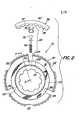
- FIG. 1 shows a synchronizing device 10 for synchronizing two rotating parts 12, 14 or 12, 64, which rotate about a common axis a-a.
- the device consists of a sleeve carrier 16, which is carried by the first rotary part 12 and is in rotary connection with this first rotary part 12 via spline teeth 18.
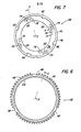
- the sleeve carrier 16, which is shown in particular in FIG. 2, has a toothed outer circumference 20 in which two groups of grooves 22, 24 arranged at the same angular distance from one another are provided.
- the grooves 22 of the first group are flat and extend over the full width of the sleeve carrier 16.
- Preferably three such grooves 22 are arranged.
- At least three of the grooves 24 of the second group are also provided. They are arranged between the grooves 22 of the first group and have a considerably greater depth; they also extend over the entire width of the sleeve carrier 16.
- a bore 26 is provided in the bottom of each groove 24 and receives a transmission device 28.
- the latter consists of a guide piece 30, a piston 32 and a spring 34.
- This transmission device extends over the sleeves Carrier 16 out and abuts a shift sleeve 36 which has a toothed inner peripheral surface 38 which engages in the toothed outer surface 20 of the sleeve carrier 16.
- the pistons 2 of the transmission device 28 are immersed in an annular groove 37 (see FIG. 3), which is arranged in the inner circumferential surface 38 of the shift sleeve 36.
- the pistons 32 are held in this groove 37 both by the guide pieces 30 and by the springs 34 which push the pistons outwards.
- the shift sleeve 36 also has an annular outer surface 40 which is capable of receiving a conventional but not shown shift fork, which is used for the axial displacement of the shift sleeve 36 with the aid of a hand lever arranged in the driver's cabin of the vehicle.
- the connection of the hand lever with the shift fork and the interaction with the shift sleeve 36 are known to an average person skilled in the art and are therefore not further explained.
- a locking ring 42, 42 ' is arranged on both sides of the sleeve carrier 16.
- the parts arranged to the left of the socket support 16 according to FIG. 1 are labeled with smooth numbers, the corresponding parts located to the right of the socket support 16 are identified by the same number, but with an additional line.
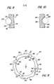
- Each locking ring 42, 42 ' which can best be seen in FIGS. 3 and 6, has a conical inner friction surface 44 which tapers radially in the direction of the sleeve carrier 16.
- the inclination is approximately 5 ° to 10 °, but preferably approximately 6.5 °, measured from the central axis of the first rotary part 12.
- third rotation part 14, 64 is a gear wheel with toothed outer surface 15 or 66, respectively. Both rotation parts 14, 64 are freely rotatable on the first rotation part 12 and can rotate independently of one another.
- the second rotary part 14 is axially fixed on its left side 59 by a shoulder 60 of the first rotary part 12 and on its right side by the sleeve carrier 16, which in turn is fixed against an axial displacement to the right by a snap ring 62.
- the third rotary part 64 is axially fixed on its right side 65 by a holding bush 67 which is firmly connected to the first rotary part 12, for example by a press fit.
- the gear ring 50 has a toothed outer surface 52, the outer diameter of which corresponds approximately to the inner diameter of the inner peripheral surface 38 of the shift sleeve 36. The latter can therefore engage with its internal teeth in the teeth of the gear ring 50 if it is axially displaced over the locking ring 42 onto the gear ring 50.
- the gear ring 50 also has a flat side surface 54 facing the sleeve carrier 16 and at least one recess 56 (see FIG. 1), which is preferably defined by the gear ring 50 extends through. Four such recesses 56 are preferably provided, which are arranged at the same angular distance from one another.
- the structure of the gear ring 50 ′ corresponds to that of the gear ring 50.
- the synchronizing device 10 further comprises a conical element 68, a pressure plate 84, a clutch friction disk 102 and a separating disk 112, which are arranged in packets on both sides of the sleeve carrier 16 between the locking ring 42, 42 'and the gear ring 50, 50'.
- the conical element 68 is a hollow ring which is arranged coaxially around the first rotating part 12 and has a conical outer friction surface 70, a first side surface 72 and stepped second and third side surfaces 74, 76.
- the conical element 68 is aligned with the locking ring 42 such that its conical inner friction surface 44 can act on the conical outer friction surface 70 of the conical element when the locking ring 42 is axially displaced against the conical element 68.
- the first side surface 72 of the conical element 68 can also non-positively act on a friction surface 73 on the side of the sleeve carrier 16.
- the friction surface 73 can be made of any known material with a high coefficient of friction.
- FIG. 7 shows a left side view of the conical element 68.
- a group of approximately lemon-shaped recesses 78 and a group of narrow, arcuate slots 79 in the second side surface 74 can be seen.
- the recesses 78 have the shape of a flat V (see FIG. 8), each with two run-up slopes 80, which lie opposite one another and are preferably inward by approximately 10 ° to 45 ° from the side surface 74 as 20 ° to 40 °, but are optimally inclined by about 35 °.
- run-up bevels 80 protrude into or out of this image plane and are aligned with the orbital movement of the conical element 68.
- These run-up bevels 80 enable the synchronizing device 10 to operate in a self-amplifying manner regardless of whether the conical element 68 is clockwise or rotates counter-rotating.
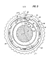
- the arcuate slots 79 which are arranged at a somewhat angular offset with respect to the recesses 78, serve to partially accommodate a tension spring 81 (see lower half of FIG. 1), one end of which in a recess 83 of the conical element 68 and the other end of which in a corresponding recess 85 in Pressure plate 84 are attached (see also Figure 5).
- tension springs 81 are preferably provided, which constantly pull the two parts 68, 84 against one another.
- the conical element 68 also preferably has four claws 82. on, which are arranged between the step between the second and third side surface 74, 76 and enable an axial displacement of the pressure plate 84 relative to the conical element 68.
- the pressure plate 84 shown in FIGS. 1, 3 and 9 surrounds the first rotary part 12 coaxially, lies next to the second side surface 74 of the conical element 68 and has a first and second side surface 86, 88 and at least three, but preferably four, at the same angular distance from one another arranged claws 90.
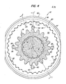
- the latter protrude from the second side surface 88 in the axial direction, as can be seen in FIG. 1, and engage in the corresponding recesses 56 in the gear ring 50.
- the width of each claw 90 corresponds approximately to the diameter of each recess 56 (see FIG. 4).
- a plurality of recesses 92 are provided in the first side surface 86 of the pressure plate 84, which correspond to the recesses 78 in the conical element 68 in terms of number, shape and arrangement.
- FIG. 10 shows that the recesses 92 also have a cross section corresponding to the recess 78 with opposing run-up slopes 94 with the same angular inclination.
- a ball 100 the diameter of which is greater than twice the depth of the recess 78 or 92, engages in each pair of opposing recesses 78, 92.
- the first side surface 86 of the pressure plate 84 always has one from the second side surface 74 of the conical element 68 certain distance.
- the balls 100 As soon as a relative rotation occurs between the conical element 68 and the pressure plate 84, the balls 100 inevitably run onto the run-up bevels 80, 94 of their recesses 78, 92 and thereby cause an axial displacement of the conical element 68 with respect to the pressure plate 84. At the same time, however, they press Balls 100 also have the conical element 68 with its first side surface 72 against the lateral friction surface 73 of the sleeve carrier 16. These forced axial displacements result regardless of whether the parts 68, 84 rotate clockwise or counterclockwise. The balls 100 cause self-reinforcement during synchronization, which will be explained in detail later.
- the first group comprises at least three, but preferably four, grooves 96 arranged at the same angular distance from one another, which lie next to the openings 85 provided in the second side surface 88. These grooves 96 correspond to the narrow, arcuately shaped slots 79 of the conical element 68 and partially accommodate the tension springs 81. The ends of these tension springs 81 are fixed in the corresponding recesses 83, 85 so that the axis of each spring 81 is parallel to the axis of the first rotary part 12, as can be seen in the lower half of FIG.
- the second group comprises at least three, but preferably four grooves 98, which receive the claws 82 of the conical element 68. The play between claws 82 and grooves 98 allows the conical element 68 to be rotated relative to the pressure plate 84.
- FIGS. 3 and 11 best show the clutch friction disk 102, which is located next to the second side wall 88 of the pressure plate 84, is annular, surrounds the first rotating part 12 coaxially and has a toothed inner surface 104 which fits into a corresponding toothed outer surface 106 of the sleeve carrier 16 intervenes. Therefore, rotate the sleeve support 16 and K upplungsreibscale 102 constantly synchronized. However, the K upplungsreibscale can be moved axially relative to the sleeve support 16 102nd
- the K upplungsreibsorption 102 is provided on its both side surfaces with a friction lining 108,110.
- the friction lining 108 acts on the second side surface 88 of the pressure plate 84 when the two parts 84, 102 are pushed axially against one another, while the friction lining 110 acts on the separating disk 112 arranged between the clutch friction disk 102 and the flat side surface 54 of the gear ring 50 when the two parts 102, 112 are axial be moved against each other.
- the cutting disc 112 shown in particular in FIGS. 1, 3, 5 and 12, has the shape of a thin ring which coaxially surrounds the first rotary part 12 and has a slightly curved outer circumference 114, in which two groups of grooves 116, 118 are arranged, each three , but preferably include four grooves.
- the grooves 116 of the first group form a passage opening for the claws 90 of the pressure plate 84, but are wider than the claws 90, so that the pressure plate 84 can make a limited revolution with respect to the cutting disc 112 when the balls 100 emerge from their recesses.
- the grooves 118 of the second group form openings for the claws 82 of the conical element (see FIG. 5), so that the conical element 68 completely surrounds the outer periphery 114 of the cutting disk 112 when the synchronizing device 10 is assembled.
- the claws 82 allow the cutting disk 112 to be axially displaced relative to the conical element 68, but at the same time ensure that the cutting disk 112 rotates synchronously with the conical element 68 are fed directly into the conical element 68.
- FIG. 13 shows tension springs 120 to be optionally provided between the locking rings 42, 42 '.
- the three, but preferably four tension springs 120 are arranged at the same angular distance from one another around the sleeve carrier 16 and protrude through bores 122 which lead in alignment with one another through the locking rings 42, 42 ′ and the sleeve carrier 16.
- the ends 124, 124 'of each tension spring 120 engage in recesses 126, 126' which are provided in the outer end faces of the two locking rings 42, 42 '.
- the tension springs 120 limit the axial displacement of the two locking rings 42, 42 'away from one another and thereby prevent frictional blocking forces which occur between the outer conical friction surface 70, 70' and the inner conical friction surfaces 44, 44 'of the parts 68, 68' and 42, 42 '. could occur.
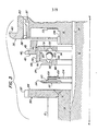
- FIGS. 1 and 3 show that sleeve carrier 16, shift sleeve 36, locking ring 42 and clutch friction disk 102 all rotate at the same speed and in the same direction as the first rotating part 12. Because the sleeve carrier 16 is connected to the first rotating part 12 via the spline 18 ; the switching sleeve 36 engages with its inner toothed peripheral surface 38 in the toothed outer surface 20 of the first rotary part 12; the locking ring 42 engages with its claws 48 in the grooves 22 of the sleeve carrier 16; the clutch friction disk 102 sits on the spline 106 of the sleeve carrier 16.
- the synchronization process begins when the shift sleeve 36 is shifted from its neutral position towards the second rotating part 14.
- the spring 34 of the transmission device 28 bends (see FIG. 2), so that the top of the piston 32 can remain in the annular groove 37 of the shift sleeve 36.
- the guide pieces 30 are brought into contact with the right side of the locking ring 42, on which one Axial force is exerted. This displaces the locking ring 42 by a fraction of a millimeter, so that the inner conical friction surface 44 acts on the outer conical friction surface 70 of the conical element 68.
- the locking ring 42 and thus its teeth 46 rotate slightly by approximately half the thickness of a tooth, so that the teeth 46 of the locking ring 42 no longer align with the toothed inner surface of the switching sleeve 36.
- the extent of this twisting movement results from the game that the claws 48 of the locking ring 42 have in the grooves 22 of the sleeve carrier 16. This misalignment blocks the shifting of the shift sleeve 36 via the locking ring 42 onto the gear ring 50 until the two rotating parts 12, 14 rotate at the same speed.
- the torque forces between the first and second rotary parts 12, 14 are transmitted via three separate independent paths: the first path is formed by the gear ring 50 via the pressure plate 84, the conical element 68, the locking ring 42 and the sleeve carrier 16 on the first rotary part 12
- the second way results from the gear ring 50 via the pressure plate 84, the clutch friction disk 102 and the sleeve carrier 16 to the first rotating part 12.
- the third way takes place from the gear ring 50 via the pressure plate 84, the conical element 68, the friction lining 73 and the sleeve carrier 16 onto the first rotary part 12.
- the second and third paths form secondary paths, while the first path represents the primary path.
- the driver will first cancel the drive of the first rotary part 12, for example by actuating a conventional clutch, and then the shift sleeve 36 by moving the articulated shift lever to the right into the position shown in Figure 3.
- the toothed inner surface 38 of the shift sleeve 36 thereby releases the gear ring 50 and moves back over the locking ring 42.
- the second rotating part 14 with the gear ring 50 attached to it can then rotate at a different speed compared to the first rotating part 12, depending on the initial load and the intermediate forces.
- the frictional connection between the two conical surfaces 44, 70 is also canceled, since no more torques act on them.
- the locking ring 42 rotates with the sleeve carrier 16 via the positive connection between claws 48 and grooves 22; the conical element 68 begins to revolve again at the speed of the gear ring 50.
- the balls 100 roll back into their recesses 78, 82, thereby allowing the conical element 68 to be axially separated from the friction lining 73, the pressure plate 84 from the friction lining 108, the Friction lining 110 from the cutting disc 112 and the left side 59 of the second rotary part 14 from the shoulder 60.
- the balls 100 are pressed into the bottom of the associated recesses 78, 92 as a result of the tensile forces exerted by the springs 81 on the conical element 68 and the pressure plate 84 . If the springs 120 are also arranged between the two locking rings 42, 42 ', they support the above-mentioned separating movement by pulling the locking ring 42 to the right and thereby canceling the frictional engagement between the two conical friction surfaces 44, 70. This ends the separation process, so that the first and second rotary parts 12, 14 can rotate independently of one another again.
- Synchronization and cancellation take place within fractions of a second; the axial displacement between the individual parts is minimal, and is, for example, only a fraction of a millimeter.
Priority Applications (1)
| Application Number | Priority Date | Filing Date | Title |
|---|---|---|---|
| AT82110052T ATE18086T1 (de) | 1981-11-13 | 1982-10-30 | Synchronisiervorrichtung zum synchronisieren zweier um eine gemeinsame achse drehender rotationsteile. |
Applications Claiming Priority (2)
| Application Number | Priority Date | Filing Date | Title |
|---|---|---|---|
| US321139 | 1981-11-13 | ||
| US06/321,139 US4413715A (en) | 1981-11-13 | 1981-11-13 | Self-energized synchronizer |
Publications (2)
| Publication Number | Publication Date |
|---|---|
| EP0086875A1 true EP0086875A1 (fr) | 1983-08-31 |
| EP0086875B1 EP0086875B1 (fr) | 1986-02-19 |
Family
ID=23249341
Family Applications (1)
| Application Number | Title | Priority Date | Filing Date |
|---|---|---|---|
| EP82110052A Expired EP0086875B1 (fr) | 1981-11-13 | 1982-10-30 | Dispositif pour la synchronisation de deux éléments à rotation coaxiale |
Country Status (12)
| Country | Link |
|---|---|
| US (1) | US4413715A (fr) |
| EP (1) | EP0086875B1 (fr) |
| JP (1) | JPS5888228A (fr) |
| AR (1) | AR232035A1 (fr) |
| AT (1) | ATE18086T1 (fr) |
| AU (1) | AU547285B2 (fr) |
| BR (1) | BR8206461A (fr) |
| CA (1) | CA1186918A (fr) |
| DE (1) | DE3269218D1 (fr) |
| DK (1) | DK504182A (fr) |
| ES (1) | ES8400811A1 (fr) |
| ZA (1) | ZA828296B (fr) |
Cited By (1)
| Publication number | Priority date | Publication date | Assignee | Title |
|---|---|---|---|---|
| AT520296B1 (de) * | 2017-11-10 | 2019-03-15 | Avl Commercial Driveline & Tractor Eng Gmbh | Schaltvorrichtung für ein getriebe |
Families Citing this family (34)
| Publication number | Priority date | Publication date | Assignee | Title |
|---|---|---|---|---|
| WO1985001998A1 (fr) * | 1983-10-26 | 1985-05-09 | Zahnradfabrik Friedrichshafen Ag | Dispositif de synchronisation a verrouillage pour boites a vitesses |
| JPH01502284A (ja) * | 1986-03-21 | 1989-08-10 | ツアーンラートファブリーク、フリードリッヒスハーフェン、アクチエンゲゼルシャフト | 変速切換装置のラッチ同期装置 |
| US5054595A (en) * | 1986-03-21 | 1991-10-08 | Zahnradfabrik Friedrichshafen Ag | Locking synchronizing means for transmission shifts |
| JP2600674B2 (ja) * | 1987-05-09 | 1997-04-16 | トヨタ自動車株式会社 | 同期装置 |
| JPH0619190B2 (ja) * | 1987-05-20 | 1994-03-16 | トヨタ自動車株式会社 | 同期装置 |
| JPH01141235A (ja) * | 1987-11-27 | 1989-06-02 | Kanzaki Kokyukoki Mfg Co Ltd | 同期噛合い式クラッチ装置 |
| US4830159A (en) * | 1988-01-29 | 1989-05-16 | Deere & Company | Multi-disk synchronizer |
| US5092438A (en) * | 1990-12-24 | 1992-03-03 | Eaton Corporation | Synchronizer with self-energizing |
| US5078245A (en) * | 1990-12-24 | 1992-01-07 | Eaton Corporation | Self-energizing synchronizer with force limiting |
| US5111922A (en) * | 1990-12-24 | 1992-05-12 | Eaton Corporation | Pre-energizer for a synchronizer |
| US5065855A (en) * | 1990-12-24 | 1991-11-19 | Eaton Corporation | Self-energizing splines for a synchronizer |
| US5078244A (en) * | 1990-12-24 | 1992-01-07 | Eaton Corporation | Self-energizing synchronizer |
| US5103952A (en) * | 1990-12-24 | 1992-04-14 | Eaton Corporation | Pre-engergizer for one-way synchronizer |
| US5086897A (en) * | 1990-12-24 | 1992-02-11 | Eaton Corporation | Pre-energizer pins for a synchronizer |
| US5092439A (en) * | 1990-12-24 | 1992-03-03 | Eaton Corporation | Synchronizer with deep splines & improved boost ramps |
| USRE35796E (en) * | 1990-12-24 | 1998-05-19 | Eaton Corporation | Self-energizing synchronizer |
| US5141087A (en) * | 1990-12-24 | 1992-08-25 | Eaton Corporation | Self-energizing synchronizer |
| US5097930A (en) * | 1990-12-24 | 1992-03-24 | Eaton Corporation | Pre-energizer for a synchronizer |
| US5161423A (en) | 1990-12-24 | 1992-11-10 | Eaton Corporation | Self-energizing synchronizer for equalizing shift time and effort of a multi-ratio transmission |
| US5135087A (en) * | 1991-01-16 | 1992-08-04 | New Venture Gear, Inc. | Dual-cone synchronizer with servo action |
| US5269400A (en) * | 1992-10-20 | 1993-12-14 | Borg-Warner Automotive, Inc. | Transmission synchronizer |
| JP2566649Y2 (ja) * | 1992-12-22 | 1998-03-30 | 株式会社 神崎高級工機製作所 | 作業車両用の多段変速装置 |
| GB9606170D0 (en) * | 1996-03-23 | 1996-05-29 | Eaton Corp | Synchronizer mechanism |
| US5735767A (en) * | 1996-10-21 | 1998-04-07 | New Venture Gear, Inc. | Add-on two-speed compounder |
| US6149543A (en) * | 1999-09-17 | 2000-11-21 | New Venture Gear, Inc. | Compounder assembly with controllable overrunning clutch |
| BR9907360A (pt) * | 1999-11-12 | 2001-06-26 | Eaton Corp | Sincronizador tipo anel de bloqueio de ação dupla |
| KR100482107B1 (ko) * | 2002-09-02 | 2005-04-13 | 현대자동차주식회사 | 수동 변속기의 싱크로나이저 장치 |
| US20040198548A1 (en) * | 2003-04-04 | 2004-10-07 | Showalter Dan J. | Synchronizer having ball ramp actuator mechanism |
| DE102010046139A1 (de) * | 2010-09-14 | 2012-03-15 | Stromag Ag | Synchronisationseinheit für eine formschlüssige Doppelschaltkupplung |
| US9683614B2 (en) | 2014-01-29 | 2017-06-20 | Eaton Corporation | Transmission gear synchronizer blocker ring formed of a thermoplastic material |
| EP3287656B1 (fr) * | 2016-08-23 | 2019-03-20 | Oerlikon Friction Systems (Germany) GmbH | Dispositif de synchronisation et boîte manuelle à engrenages pour un véhicule |
| EP3287655B1 (fr) * | 2016-08-23 | 2019-03-20 | Oerlikon Friction Systems (Germany) GmbH | Dispositif de synchronisation et boîte manuelle à engrenages pour un véhicule |
| DE102017202713A1 (de) * | 2017-02-20 | 2018-08-23 | Bayerische Motoren Werke Aktiengesellschaft | Schaltgetriebe und Verfahren zum Schalten eines Schaltgetriebes |
| CN107906141A (zh) * | 2017-12-12 | 2018-04-13 | 郑州科技学院 | 适用于新能源汽车的锁环式同步器及变速器 |
Citations (9)
| Publication number | Priority date | Publication date | Assignee | Title |
|---|---|---|---|---|
| DE738514C (de) * | 1939-08-17 | 1943-08-19 | Zahnradfabrik Friedrichshafen | Synchronisierungsvorrichtung fuer Klauenkupplungen |
| FR1332492A (fr) * | 1962-08-29 | 1963-07-12 | Porsche Kg | Dispositif de synchronisation pour mécanisme de changement de vitesse, notamment pour véhicules automobiles |
| US3286801A (en) * | 1964-07-17 | 1966-11-22 | Dana Corp | Synchronizing clutch with multiple conical discs |
| US3386302A (en) * | 1966-05-02 | 1968-06-04 | Ford Motor Co | Multiple speed ratio, synchronized torque transmission mechanism |
| DE1284309B (de) * | 1966-06-21 | 1968-11-28 | Steyr Daimler Puch Ag | Gangschalt- und Synchronisierkupplung fuer Zahnraederwechselgetriebe von Kraftfahrzeugen |
| GB1137332A (en) * | 1965-05-03 | 1968-12-18 | Borg Warner | Synchronizer mechanism |
| DE1910884A1 (de) * | 1969-03-04 | 1970-09-10 | Zahnradfabrik Friedrichshafen | Synchronisiervorrichtung fuer Zahnraederwechselgetriebe |
| DE1755457A1 (de) * | 1968-04-09 | 1971-05-06 | Michael Meyerle | Synchronisier- und Gangschaltvorrichtung,insbesondere fuer Kraftfahrzeug-Wechselgetriebe |
| US4185725A (en) * | 1977-05-17 | 1980-01-29 | General Motors Corporation | Synchronizer arrangements for stepped-ratio transmissions |
Family Cites Families (5)
| Publication number | Priority date | Publication date | Assignee | Title |
|---|---|---|---|---|
| US2745529A (en) * | 1953-09-26 | 1956-05-15 | Volkswagenwerk Ag | Synchronizing gears |
| US2941641A (en) * | 1955-09-21 | 1960-06-21 | Daimler Benz Ag | Synchronizing clutch |
| DE1170795B (de) * | 1961-09-20 | 1964-05-21 | Porsche Kg | Gleichlaufeinrichtung fuer Geschwindigkeits-wechselgetriebe, insbesondere fuer Kraftfahrzeuge |
| DE2045383B2 (de) * | 1970-09-14 | 1971-12-09 | Carl Hurth Maschinen und Zahnrad fabrik, 8000 München | Schalteinrichtung fuer eine reibungskupplung |
| JPS4915861A (fr) * | 1972-06-13 | 1974-02-12 |
-
1981
- 1981-11-13 US US06/321,139 patent/US4413715A/en not_active Expired - Fee Related
-
1982
- 1982-10-07 AU AU89200/82A patent/AU547285B2/en not_active Ceased
- 1982-10-30 AT AT82110052T patent/ATE18086T1/de not_active IP Right Cessation
- 1982-10-30 EP EP82110052A patent/EP0086875B1/fr not_active Expired
- 1982-10-30 DE DE8282110052T patent/DE3269218D1/de not_active Expired
- 1982-11-03 CA CA000414752A patent/CA1186918A/fr not_active Expired
- 1982-11-08 BR BR8206461A patent/BR8206461A/pt unknown
- 1982-11-11 ZA ZA828296A patent/ZA828296B/xx unknown
- 1982-11-12 DK DK504182A patent/DK504182A/da not_active Application Discontinuation
- 1982-11-12 AR AR291282A patent/AR232035A1/es active
- 1982-11-12 ES ES517311A patent/ES8400811A1/es not_active Expired
- 1982-11-13 JP JP57199655A patent/JPS5888228A/ja active Pending
Patent Citations (9)
| Publication number | Priority date | Publication date | Assignee | Title |
|---|---|---|---|---|
| DE738514C (de) * | 1939-08-17 | 1943-08-19 | Zahnradfabrik Friedrichshafen | Synchronisierungsvorrichtung fuer Klauenkupplungen |
| FR1332492A (fr) * | 1962-08-29 | 1963-07-12 | Porsche Kg | Dispositif de synchronisation pour mécanisme de changement de vitesse, notamment pour véhicules automobiles |
| US3286801A (en) * | 1964-07-17 | 1966-11-22 | Dana Corp | Synchronizing clutch with multiple conical discs |
| GB1137332A (en) * | 1965-05-03 | 1968-12-18 | Borg Warner | Synchronizer mechanism |
| US3386302A (en) * | 1966-05-02 | 1968-06-04 | Ford Motor Co | Multiple speed ratio, synchronized torque transmission mechanism |
| DE1284309B (de) * | 1966-06-21 | 1968-11-28 | Steyr Daimler Puch Ag | Gangschalt- und Synchronisierkupplung fuer Zahnraederwechselgetriebe von Kraftfahrzeugen |
| DE1755457A1 (de) * | 1968-04-09 | 1971-05-06 | Michael Meyerle | Synchronisier- und Gangschaltvorrichtung,insbesondere fuer Kraftfahrzeug-Wechselgetriebe |
| DE1910884A1 (de) * | 1969-03-04 | 1970-09-10 | Zahnradfabrik Friedrichshafen | Synchronisiervorrichtung fuer Zahnraederwechselgetriebe |
| US4185725A (en) * | 1977-05-17 | 1980-01-29 | General Motors Corporation | Synchronizer arrangements for stepped-ratio transmissions |
Cited By (2)
| Publication number | Priority date | Publication date | Assignee | Title |
|---|---|---|---|---|
| AT520296B1 (de) * | 2017-11-10 | 2019-03-15 | Avl Commercial Driveline & Tractor Eng Gmbh | Schaltvorrichtung für ein getriebe |
| AT520296A4 (de) * | 2017-11-10 | 2019-03-15 | Avl Commercial Driveline & Tractor Eng Gmbh | Schaltvorrichtung für ein getriebe |
Also Published As
| Publication number | Publication date |
|---|---|
| ATE18086T1 (de) | 1986-03-15 |
| AU547285B2 (en) | 1985-10-10 |
| BR8206461A (pt) | 1983-09-27 |
| DE3269218D1 (en) | 1986-03-27 |
| CA1186918A (fr) | 1985-05-14 |
| JPS5888228A (ja) | 1983-05-26 |
| ES517311A0 (es) | 1983-11-01 |
| ES8400811A1 (es) | 1983-11-01 |
| AR232035A1 (es) | 1985-04-30 |
| DK504182A (da) | 1983-05-14 |
| US4413715A (en) | 1983-11-08 |
| ZA828296B (en) | 1984-06-27 |
| EP0086875B1 (fr) | 1986-02-19 |
| AU8920082A (en) | 1983-05-19 |
Similar Documents
| Publication | Publication Date | Title |
|---|---|---|
| EP0086875B1 (fr) | Dispositif pour la synchronisation de deux éléments à rotation coaxiale | |
| DE2512248C3 (de) | Sperrsynchronisationseinrichtung für ein Wechselgetriebe | |
| DE3622464C1 (fr) | ||
| DE1630426B2 (de) | Sperrbares ausgleichgetrieb e fuer fahrzeuge | |
| EP0184077A1 (fr) | Dispositif de synchronisation pour embrayages | |
| EP0157908B1 (fr) | Dispositif de synchronisation pour boîte de vitesses | |
| DE3324355C2 (de) | Fliehkraftkupplung | |
| DE2949194C2 (de) | Mechanische Schalteinrichtung für ein Kraftfahrzeug-Wechselgetriebe | |
| EP0328910B1 (fr) | Appareil de synchronisation pour transmission synchronisée | |
| EP0248899B1 (fr) | Boite de changement a echelonnement multiple de vitesses | |
| DE19543645B4 (de) | Vorrichtung zum Schalten von sperrsynchronisierten Fahrzeuggetrieben | |
| DE2751699C3 (de) | Einrichtung zur geräuschlosen Schaltung eines Rückwärtsganges von Geschwindigkeitswechselgetrieben, insbesondere von Kraftfahrzeugen | |
| DE102007022544B4 (de) | Schaltkupplungsanordnung | |
| DD295700A5 (de) | Freilaufkupplung | |
| DE2815202A1 (de) | Schaltgetriebe | |
| DE2706661A1 (de) | Synchronisiereinrichtung fuer ein kraftfahrzeug-zahnraederwechselgetriebe | |
| DE2848288C2 (fr) | ||
| DE3729818C2 (fr) | ||
| DE4038731C2 (de) | Kupplungseinrichtung zum Verbinden zweier mit unterschiedlicher Drehzahl rotierender Wellen | |
| DE3623142C2 (fr) | ||
| DE60108933T2 (de) | Synchronisiereinrichtung | |
| DE2820774C2 (de) | Synchronisiereinrichtung für Schaltgetriebe | |
| DE3009853B1 (de) | Fliehkraftschaltkupplung | |
| DE925443C (de) | Synchronisiereinrichtung | |
| EP0727599B1 (fr) | Dispositif de changement de vitesse pour transmission |
Legal Events
| Date | Code | Title | Description |
|---|---|---|---|
| PUAI | Public reference made under article 153(3) epc to a published international application that has entered the european phase |
Free format text: ORIGINAL CODE: 0009012 |
|
| AK | Designated contracting states |
Designated state(s): AT BE DE FR GB IT NL SE |
|
| 17P | Request for examination filed |
Effective date: 19830727 |
|
| ITCL | It: translation for ep claims filed |
Representative=s name: LENZI & C. |
|
| EL | Fr: translation of claims filed | ||
| TCNL | Nl: translation of patent claims filed | ||
| ITF | It: translation for a ep patent filed |
Owner name: LENZI & C. |
|
| GRAA | (expected) grant |
Free format text: ORIGINAL CODE: 0009210 |
|
| AK | Designated contracting states |
Designated state(s): AT BE DE FR GB IT NL SE |
|
| REF | Corresponds to: |
Ref document number: 18086 Country of ref document: AT Date of ref document: 19860315 Kind code of ref document: T |
|
| REF | Corresponds to: |
Ref document number: 3269218 Country of ref document: DE Date of ref document: 19860327 |
|
| ET | Fr: translation filed | ||
| PGFP | Annual fee paid to national office [announced via postgrant information from national office to epo] |
Ref country code: AT Payment date: 19861015 Year of fee payment: 5 |
|
| PGFP | Annual fee paid to national office [announced via postgrant information from national office to epo] |
Ref country code: NL Payment date: 19861031 Year of fee payment: 5 |
|
| PLBE | No opposition filed within time limit |
Free format text: ORIGINAL CODE: 0009261 |
|
| STAA | Information on the status of an ep patent application or granted ep patent |
Free format text: STATUS: NO OPPOSITION FILED WITHIN TIME LIMIT |
|
| 26N | No opposition filed | ||
| PG25 | Lapsed in a contracting state [announced via postgrant information from national office to epo] |
Ref country code: AT Effective date: 19871030 |
|
| PG25 | Lapsed in a contracting state [announced via postgrant information from national office to epo] |
Ref country code: SE Effective date: 19871031 Ref country code: BE Effective date: 19871031 |
|
| BERE | Be: lapsed |
Owner name: DEERE & CY Effective date: 19871031 |
|
| PG25 | Lapsed in a contracting state [announced via postgrant information from national office to epo] |
Ref country code: NL Effective date: 19880501 |
|
| NLV4 | Nl: lapsed or anulled due to non-payment of the annual fee | ||
| GBPC | Gb: european patent ceased through non-payment of renewal fee | ||
| PG25 | Lapsed in a contracting state [announced via postgrant information from national office to epo] |
Ref country code: FR Free format text: LAPSE BECAUSE OF NON-PAYMENT OF DUE FEES Effective date: 19880630 |
|
| REG | Reference to a national code |
Ref country code: FR Ref legal event code: ST |
|
| PG25 | Lapsed in a contracting state [announced via postgrant information from national office to epo] |
Ref country code: GB Effective date: 19881122 |
|
| PG25 | Lapsed in a contracting state [announced via postgrant information from national office to epo] |
Ref country code: DE Effective date: 19900703 |
|
| EUG | Se: european patent has lapsed |
Ref document number: 82110052.6 Effective date: 19880712 |