EP0086875A1 - Device for synchronising two parts rotatable about the same axis - Google Patents
Device for synchronising two parts rotatable about the same axis Download PDFInfo
- Publication number
- EP0086875A1 EP0086875A1 EP82110052A EP82110052A EP0086875A1 EP 0086875 A1 EP0086875 A1 EP 0086875A1 EP 82110052 A EP82110052 A EP 82110052A EP 82110052 A EP82110052 A EP 82110052A EP 0086875 A1 EP0086875 A1 EP 0086875A1
- Authority
- EP
- European Patent Office
- Prior art keywords
- pressure plate
- friction
- sleeve carrier
- conical element
- gear ring
- Prior art date
- Legal status (The legal status is an assumption and is not a legal conclusion. Google has not performed a legal analysis and makes no representation as to the accuracy of the status listed.)
- Granted
Links
Images


Classifications
-
- F—MECHANICAL ENGINEERING; LIGHTING; HEATING; WEAPONS; BLASTING
- F16—ENGINEERING ELEMENTS AND UNITS; GENERAL MEASURES FOR PRODUCING AND MAINTAINING EFFECTIVE FUNCTIONING OF MACHINES OR INSTALLATIONS; THERMAL INSULATION IN GENERAL
- F16D—COUPLINGS FOR TRANSMITTING ROTATION; CLUTCHES; BRAKES
- F16D23/00—Details of mechanically-actuated clutches not specific for one distinct type
- F16D23/02—Arrangements for synchronisation, also for power-operated clutches
- F16D23/04—Arrangements for synchronisation, also for power-operated clutches with an additional friction clutch
- F16D23/06—Arrangements for synchronisation, also for power-operated clutches with an additional friction clutch and a blocking mechanism preventing the engagement of the main clutch prior to synchronisation
- F16D2023/0618—Details of blocking mechanism comprising a helical spring loaded element, e.g. ball
-
- F—MECHANICAL ENGINEERING; LIGHTING; HEATING; WEAPONS; BLASTING
- F16—ENGINEERING ELEMENTS AND UNITS; GENERAL MEASURES FOR PRODUCING AND MAINTAINING EFFECTIVE FUNCTIONING OF MACHINES OR INSTALLATIONS; THERMAL INSULATION IN GENERAL
- F16D—COUPLINGS FOR TRANSMITTING ROTATION; CLUTCHES; BRAKES
- F16D23/00—Details of mechanically-actuated clutches not specific for one distinct type
- F16D23/02—Arrangements for synchronisation, also for power-operated clutches
- F16D23/04—Arrangements for synchronisation, also for power-operated clutches with an additional friction clutch
- F16D23/06—Arrangements for synchronisation, also for power-operated clutches with an additional friction clutch and a blocking mechanism preventing the engagement of the main clutch prior to synchronisation
- F16D2023/0643—Synchro friction clutches with flat plates, discs or lamellae
-
- F—MECHANICAL ENGINEERING; LIGHTING; HEATING; WEAPONS; BLASTING
- F16—ENGINEERING ELEMENTS AND UNITS; GENERAL MEASURES FOR PRODUCING AND MAINTAINING EFFECTIVE FUNCTIONING OF MACHINES OR INSTALLATIONS; THERMAL INSULATION IN GENERAL
- F16D—COUPLINGS FOR TRANSMITTING ROTATION; CLUTCHES; BRAKES
- F16D23/00—Details of mechanically-actuated clutches not specific for one distinct type
- F16D23/02—Arrangements for synchronisation, also for power-operated clutches
- F16D23/04—Arrangements for synchronisation, also for power-operated clutches with an additional friction clutch
- F16D23/06—Arrangements for synchronisation, also for power-operated clutches with an additional friction clutch and a blocking mechanism preventing the engagement of the main clutch prior to synchronisation
- F16D2023/065—Means to provide additional axial force for self-energising, e.g. by using torque from the friction clutch
Definitions
- the invention relates to a synchronizing device for synchronizing two rotating parts rotating about a common axis, consisting of a sleeve carrier which sits on the first of the two rotating parts, rotates with the latter and has a toothed outer circumference; a shift sleeve which engages with a toothed inner surface in the toothed outer periphery of the sleeve carrier and is axially displaceable thereon; a locking ring which is arranged next to the sleeve carrier and is axially displaceable with respect thereto, and has a toothed outer surface, a friction surface and claws for limited rotation between the sleeve carrier and locking ring; a gear ring which is in fixed rotary connection with the second rotating part and has a toothed outer surface which engages in the toothed inner surface of the shift sleeve when the latter is axially displaced over the locking ring on the gear ring.
- Such synchronization devices are used, for example, in transmissions of motor vehicles to enable trouble-free shifting of the different gears.
- the synchronization devices must be designed heavier in order to absorb the higher inertia forces of the transmission and the drive clutch.
- this synchronizing device With increasing size and weight of this synchronizing device, there was a need for a more sensitive synchronizing device, which has an increased energy capacity without increasing its external dimensions.
- a synchronizing and gear shifting device in particular for motor vehicle change gearboxes, in which, in addition to a gearwheel which is loosely rotatable, axially immovably mounted on a shaft, an axially non-displaceable sleeve carrier which is non-rotatably connected to the shaft and which has an axially displaceable, is arranged with carries a non-rotatable shifting sleeve provided with counter-claws.
- the latter can be brought into engagement with a clutch claw ring connected to the gearwheel, an axially displaceable, limitedly rotatable synchronizer ring having a conical counter friction surface being provided in recesses of the sleeve carrier, the counterpart of which friction surface cooperates with a conical friction surface on the gear to achieve synchronization before engaging the mating claws in the clutch claw ring.
- the shifting movement of the shift sleeve can be transmitted to the synchronizing ring via radially directed transmission elements which are resilient in the radial direction.
- the contact pressure is increased by the contact body interacting with the synchronizer ring and the sleeve carrier.
- the latter stored loosely in through recesses of the synchronizer ring and recesses of the sleeve carrier K formed äfigen such that upon rotation of the synchronizer ring an axial force component arises.
- the pressure body can be designed as rollers, which are arranged between two opposing wedge surfaces on the synchronizer ring and on the sleeve carrier. These roller-shaped pressing bodies thus bring about an axial displacement between two of the synchronizing components and thereby increase the synchronizing torque.
- the pressing bodies mentioned are thus self-reinforcing agents.
- the invention is therefore based on the object of improving the synchronizing device explained at the outset in such a way that it is particularly suitable for transmission gears of motor vehicles and is more sensitive to switching operations.
- the friction surface of the locking ring forms an inner cone, from which an outer cone of an axially displaceable conical element belonging to the self-reinforcing means can be acted upon, and that an axially displaceable pressure plate is arranged between the gear ring and the conical element, which is arranged on the conical element Element-associated side has a plurality of recesses which are aligned with corresponding recesses in the opposite side of the conical element, a roller body being provided between each pair of the recesses, which axially push these two parts apart during a relative rotation between the conical element and the pressure plate.
- a separating disc is arranged between the gear ring and the pressure plate, which feeds a torque into the conical element and rotates with it, and that between the pressure plate and the cutting disc is arranged the friction element which acts on these two parts in a force-locking manner, with one being caused by axial displacement between locking ring and conical element caused frictional connection of these two parts with different rotation of the conical element and pressure plate, the rolling element press the pressure plate in the direction of the gear ring and thereby establish a non-positive connection between the pressure plate and the friction element on the one hand and between the friction element and cutting disc on the other.
- the frictional connection between the pressure plate and the friction element which is preferably designed as a clutch friction disc, supports the reduction of the relative rotation between the first and second rotating part, and the conical element acts on the locking ring in a force-locking manner.
- the construction according to the invention not only increases the energy capacity of the synchronizing device, but also divides the torque transmission between the first and second rotating part into two separate and independent paths: one path is formed by the gear ring via the pressure plate, the conical element, the locking ring and the Sleeve carrier on the first rotating part.
- the second way is formed by the gear ring on the pressure plate, the clutch friction disc and the sleeve carrier on the first rotating part.
- the new synchronizing device has an increased torque and energy capacity compared to conventional embodiments.
- the conical element that creates a frictional connection and the clutch friction disk that effects a frictional connection lead to a more sensitive synchronization between the two rotating parts.
- the new synchronization device is particularly suitable for cross-country vehicles.
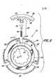
- FIG. 1 shows a synchronizing device 10 for synchronizing two rotating parts 12, 14 or 12, 64, which rotate about a common axis a-a.
- the device consists of a sleeve carrier 16, which is carried by the first rotary part 12 and is in rotary connection with this first rotary part 12 via spline teeth 18.
- the sleeve carrier 16, which is shown in particular in FIG. 2, has a toothed outer circumference 20 in which two groups of grooves 22, 24 arranged at the same angular distance from one another are provided.
- the grooves 22 of the first group are flat and extend over the full width of the sleeve carrier 16.
- Preferably three such grooves 22 are arranged.
- At least three of the grooves 24 of the second group are also provided. They are arranged between the grooves 22 of the first group and have a considerably greater depth; they also extend over the entire width of the sleeve carrier 16.
- a bore 26 is provided in the bottom of each groove 24 and receives a transmission device 28.
- the latter consists of a guide piece 30, a piston 32 and a spring 34.
- This transmission device extends over the sleeves Carrier 16 out and abuts a shift sleeve 36 which has a toothed inner peripheral surface 38 which engages in the toothed outer surface 20 of the sleeve carrier 16.
- the pistons 2 of the transmission device 28 are immersed in an annular groove 37 (see FIG. 3), which is arranged in the inner circumferential surface 38 of the shift sleeve 36.
- the pistons 32 are held in this groove 37 both by the guide pieces 30 and by the springs 34 which push the pistons outwards.
- the shift sleeve 36 also has an annular outer surface 40 which is capable of receiving a conventional but not shown shift fork, which is used for the axial displacement of the shift sleeve 36 with the aid of a hand lever arranged in the driver's cabin of the vehicle.
- the connection of the hand lever with the shift fork and the interaction with the shift sleeve 36 are known to an average person skilled in the art and are therefore not further explained.
- a locking ring 42, 42 ' is arranged on both sides of the sleeve carrier 16.
- the parts arranged to the left of the socket support 16 according to FIG. 1 are labeled with smooth numbers, the corresponding parts located to the right of the socket support 16 are identified by the same number, but with an additional line.
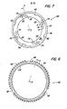
- Each locking ring 42, 42 ' which can best be seen in FIGS. 3 and 6, has a conical inner friction surface 44 which tapers radially in the direction of the sleeve carrier 16.
- the inclination is approximately 5 ° to 10 °, but preferably approximately 6.5 °, measured from the central axis of the first rotary part 12.
- third rotation part 14, 64 is a gear wheel with toothed outer surface 15 or 66, respectively. Both rotation parts 14, 64 are freely rotatable on the first rotation part 12 and can rotate independently of one another.
- the second rotary part 14 is axially fixed on its left side 59 by a shoulder 60 of the first rotary part 12 and on its right side by the sleeve carrier 16, which in turn is fixed against an axial displacement to the right by a snap ring 62.
- the third rotary part 64 is axially fixed on its right side 65 by a holding bush 67 which is firmly connected to the first rotary part 12, for example by a press fit.
- the gear ring 50 has a toothed outer surface 52, the outer diameter of which corresponds approximately to the inner diameter of the inner peripheral surface 38 of the shift sleeve 36. The latter can therefore engage with its internal teeth in the teeth of the gear ring 50 if it is axially displaced over the locking ring 42 onto the gear ring 50.
- the gear ring 50 also has a flat side surface 54 facing the sleeve carrier 16 and at least one recess 56 (see FIG. 1), which is preferably defined by the gear ring 50 extends through. Four such recesses 56 are preferably provided, which are arranged at the same angular distance from one another.
- the structure of the gear ring 50 ′ corresponds to that of the gear ring 50.
- the synchronizing device 10 further comprises a conical element 68, a pressure plate 84, a clutch friction disk 102 and a separating disk 112, which are arranged in packets on both sides of the sleeve carrier 16 between the locking ring 42, 42 'and the gear ring 50, 50'.
- the conical element 68 is a hollow ring which is arranged coaxially around the first rotating part 12 and has a conical outer friction surface 70, a first side surface 72 and stepped second and third side surfaces 74, 76.
- the conical element 68 is aligned with the locking ring 42 such that its conical inner friction surface 44 can act on the conical outer friction surface 70 of the conical element when the locking ring 42 is axially displaced against the conical element 68.
- the first side surface 72 of the conical element 68 can also non-positively act on a friction surface 73 on the side of the sleeve carrier 16.
- the friction surface 73 can be made of any known material with a high coefficient of friction.
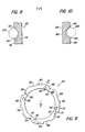
- FIG. 7 shows a left side view of the conical element 68.
- a group of approximately lemon-shaped recesses 78 and a group of narrow, arcuate slots 79 in the second side surface 74 can be seen.
- the recesses 78 have the shape of a flat V (see FIG. 8), each with two run-up slopes 80, which lie opposite one another and are preferably inward by approximately 10 ° to 45 ° from the side surface 74 as 20 ° to 40 °, but are optimally inclined by about 35 °.
- run-up bevels 80 protrude into or out of this image plane and are aligned with the orbital movement of the conical element 68.
- These run-up bevels 80 enable the synchronizing device 10 to operate in a self-amplifying manner regardless of whether the conical element 68 is clockwise or rotates counter-rotating.
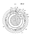
- the arcuate slots 79 which are arranged at a somewhat angular offset with respect to the recesses 78, serve to partially accommodate a tension spring 81 (see lower half of FIG. 1), one end of which in a recess 83 of the conical element 68 and the other end of which in a corresponding recess 85 in Pressure plate 84 are attached (see also Figure 5).
- tension springs 81 are preferably provided, which constantly pull the two parts 68, 84 against one another.
- the conical element 68 also preferably has four claws 82. on, which are arranged between the step between the second and third side surface 74, 76 and enable an axial displacement of the pressure plate 84 relative to the conical element 68.
- the pressure plate 84 shown in FIGS. 1, 3 and 9 surrounds the first rotary part 12 coaxially, lies next to the second side surface 74 of the conical element 68 and has a first and second side surface 86, 88 and at least three, but preferably four, at the same angular distance from one another arranged claws 90.
- the latter protrude from the second side surface 88 in the axial direction, as can be seen in FIG. 1, and engage in the corresponding recesses 56 in the gear ring 50.
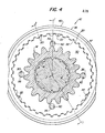
- the width of each claw 90 corresponds approximately to the diameter of each recess 56 (see FIG. 4).
- a plurality of recesses 92 are provided in the first side surface 86 of the pressure plate 84, which correspond to the recesses 78 in the conical element 68 in terms of number, shape and arrangement.
- FIG. 10 shows that the recesses 92 also have a cross section corresponding to the recess 78 with opposing run-up slopes 94 with the same angular inclination.
- a ball 100 the diameter of which is greater than twice the depth of the recess 78 or 92, engages in each pair of opposing recesses 78, 92.
- the first side surface 86 of the pressure plate 84 always has one from the second side surface 74 of the conical element 68 certain distance.
- the balls 100 As soon as a relative rotation occurs between the conical element 68 and the pressure plate 84, the balls 100 inevitably run onto the run-up bevels 80, 94 of their recesses 78, 92 and thereby cause an axial displacement of the conical element 68 with respect to the pressure plate 84. At the same time, however, they press Balls 100 also have the conical element 68 with its first side surface 72 against the lateral friction surface 73 of the sleeve carrier 16. These forced axial displacements result regardless of whether the parts 68, 84 rotate clockwise or counterclockwise. The balls 100 cause self-reinforcement during synchronization, which will be explained in detail later.
- the first group comprises at least three, but preferably four, grooves 96 arranged at the same angular distance from one another, which lie next to the openings 85 provided in the second side surface 88. These grooves 96 correspond to the narrow, arcuately shaped slots 79 of the conical element 68 and partially accommodate the tension springs 81. The ends of these tension springs 81 are fixed in the corresponding recesses 83, 85 so that the axis of each spring 81 is parallel to the axis of the first rotary part 12, as can be seen in the lower half of FIG.
- the second group comprises at least three, but preferably four grooves 98, which receive the claws 82 of the conical element 68. The play between claws 82 and grooves 98 allows the conical element 68 to be rotated relative to the pressure plate 84.
- FIGS. 3 and 11 best show the clutch friction disk 102, which is located next to the second side wall 88 of the pressure plate 84, is annular, surrounds the first rotating part 12 coaxially and has a toothed inner surface 104 which fits into a corresponding toothed outer surface 106 of the sleeve carrier 16 intervenes. Therefore, rotate the sleeve support 16 and K upplungsreibscale 102 constantly synchronized. However, the K upplungsreibscale can be moved axially relative to the sleeve support 16 102nd
- the K upplungsreibsorption 102 is provided on its both side surfaces with a friction lining 108,110.
- the friction lining 108 acts on the second side surface 88 of the pressure plate 84 when the two parts 84, 102 are pushed axially against one another, while the friction lining 110 acts on the separating disk 112 arranged between the clutch friction disk 102 and the flat side surface 54 of the gear ring 50 when the two parts 102, 112 are axial be moved against each other.
- the cutting disc 112 shown in particular in FIGS. 1, 3, 5 and 12, has the shape of a thin ring which coaxially surrounds the first rotary part 12 and has a slightly curved outer circumference 114, in which two groups of grooves 116, 118 are arranged, each three , but preferably include four grooves.
- the grooves 116 of the first group form a passage opening for the claws 90 of the pressure plate 84, but are wider than the claws 90, so that the pressure plate 84 can make a limited revolution with respect to the cutting disc 112 when the balls 100 emerge from their recesses.
- the grooves 118 of the second group form openings for the claws 82 of the conical element (see FIG. 5), so that the conical element 68 completely surrounds the outer periphery 114 of the cutting disk 112 when the synchronizing device 10 is assembled.
- the claws 82 allow the cutting disk 112 to be axially displaced relative to the conical element 68, but at the same time ensure that the cutting disk 112 rotates synchronously with the conical element 68 are fed directly into the conical element 68.
- FIG. 13 shows tension springs 120 to be optionally provided between the locking rings 42, 42 '.
- the three, but preferably four tension springs 120 are arranged at the same angular distance from one another around the sleeve carrier 16 and protrude through bores 122 which lead in alignment with one another through the locking rings 42, 42 ′ and the sleeve carrier 16.
- the ends 124, 124 'of each tension spring 120 engage in recesses 126, 126' which are provided in the outer end faces of the two locking rings 42, 42 '.
- the tension springs 120 limit the axial displacement of the two locking rings 42, 42 'away from one another and thereby prevent frictional blocking forces which occur between the outer conical friction surface 70, 70' and the inner conical friction surfaces 44, 44 'of the parts 68, 68' and 42, 42 '. could occur.
- FIGS. 1 and 3 show that sleeve carrier 16, shift sleeve 36, locking ring 42 and clutch friction disk 102 all rotate at the same speed and in the same direction as the first rotating part 12. Because the sleeve carrier 16 is connected to the first rotating part 12 via the spline 18 ; the switching sleeve 36 engages with its inner toothed peripheral surface 38 in the toothed outer surface 20 of the first rotary part 12; the locking ring 42 engages with its claws 48 in the grooves 22 of the sleeve carrier 16; the clutch friction disk 102 sits on the spline 106 of the sleeve carrier 16.
- the synchronization process begins when the shift sleeve 36 is shifted from its neutral position towards the second rotating part 14.
- the spring 34 of the transmission device 28 bends (see FIG. 2), so that the top of the piston 32 can remain in the annular groove 37 of the shift sleeve 36.
- the guide pieces 30 are brought into contact with the right side of the locking ring 42, on which one Axial force is exerted. This displaces the locking ring 42 by a fraction of a millimeter, so that the inner conical friction surface 44 acts on the outer conical friction surface 70 of the conical element 68.
- the locking ring 42 and thus its teeth 46 rotate slightly by approximately half the thickness of a tooth, so that the teeth 46 of the locking ring 42 no longer align with the toothed inner surface of the switching sleeve 36.
- the extent of this twisting movement results from the game that the claws 48 of the locking ring 42 have in the grooves 22 of the sleeve carrier 16. This misalignment blocks the shifting of the shift sleeve 36 via the locking ring 42 onto the gear ring 50 until the two rotating parts 12, 14 rotate at the same speed.
- the torque forces between the first and second rotary parts 12, 14 are transmitted via three separate independent paths: the first path is formed by the gear ring 50 via the pressure plate 84, the conical element 68, the locking ring 42 and the sleeve carrier 16 on the first rotary part 12
- the second way results from the gear ring 50 via the pressure plate 84, the clutch friction disk 102 and the sleeve carrier 16 to the first rotating part 12.
- the third way takes place from the gear ring 50 via the pressure plate 84, the conical element 68, the friction lining 73 and the sleeve carrier 16 onto the first rotary part 12.
- the second and third paths form secondary paths, while the first path represents the primary path.
- the driver will first cancel the drive of the first rotary part 12, for example by actuating a conventional clutch, and then the shift sleeve 36 by moving the articulated shift lever to the right into the position shown in Figure 3.
- the toothed inner surface 38 of the shift sleeve 36 thereby releases the gear ring 50 and moves back over the locking ring 42.
- the second rotating part 14 with the gear ring 50 attached to it can then rotate at a different speed compared to the first rotating part 12, depending on the initial load and the intermediate forces.
- the frictional connection between the two conical surfaces 44, 70 is also canceled, since no more torques act on them.
- the locking ring 42 rotates with the sleeve carrier 16 via the positive connection between claws 48 and grooves 22; the conical element 68 begins to revolve again at the speed of the gear ring 50.
- the balls 100 roll back into their recesses 78, 82, thereby allowing the conical element 68 to be axially separated from the friction lining 73, the pressure plate 84 from the friction lining 108, the Friction lining 110 from the cutting disc 112 and the left side 59 of the second rotary part 14 from the shoulder 60.
- the balls 100 are pressed into the bottom of the associated recesses 78, 92 as a result of the tensile forces exerted by the springs 81 on the conical element 68 and the pressure plate 84 . If the springs 120 are also arranged between the two locking rings 42, 42 ', they support the above-mentioned separating movement by pulling the locking ring 42 to the right and thereby canceling the frictional engagement between the two conical friction surfaces 44, 70. This ends the separation process, so that the first and second rotary parts 12, 14 can rotate independently of one another again.
- Synchronization and cancellation take place within fractions of a second; the axial displacement between the individual parts is minimal, and is, for example, only a fraction of a millimeter.
Abstract
Eine selbstverstärkende Synchronisiervorrichtung (10) zum Synchronisieren zweier um eine gemeinsame Achse (a-a) drehender Rotationsteile (12,14) besteht aus einem Muffenträger (16), der auf dem ersten Rotationsteil (12) sitzt und im Eingriff steht mit einer ringförmigen Schaltmuffe (36). Neben der Schaltmuffe (36) ist ein axial verschiebbarer Sperring (42) mit einer Reibfläche (44) angeordnet. Auf der anderen Seite des Sperringes (42), gegenüber von dem Muffenträger (16), ist ein Getriebering (50) vorgesehen, der mit dem zweiten Rotationsteil (14) in fester Drehverbindung steht. Die Verbesserung der Synchronisiervorrichtung (10) umfaßt eine Kupplungsreibscheibe (102) sowie eine selbstverstärkende Einrichtung (68,84,100,112) zur Übertragung von Reibungskräften zwischen dem ersten und zweiten Rotationsteil (12,14). Die Selbstverstärkungseinrichtung ist so angeordnet, daß sie den Sperring (42) beaufschlagt, während die Kupplungsreibscheibe (102) zwischen Getriebering (50) und Selbstverstärkungseinrichtung positioniert ist. Wenn die Bedienungsperson die Schaltmuffe (36) axial verschiebt, wird der Sperring (42) mit der Selbstverstärkungsreinrichtung in Kontakt gebracht, von der ein Teil in axialer Richtung in Kontakt mit der Kupplungsreibscheibe (102) gedrückt gedrückt wird. Diese Beaufschlagung führt dazu, daß die Kupplungsreibscheibe zur Verminderung der Relativrotation zwischen dem ersten und zweiten Rotationsteil (12,14) beiträgt, sowie die Selbstverstärkungseinrichtung den Sperring (42) kraftschlüssig beaufschlagt.A self-energizing synchronizing device (10) for synchronizing two rotating parts (12, 14) rotating about a common axis (aa) consists of a sleeve carrier (16) which sits on the first rotating part (12) and is in engagement with an annular switching sleeve (36 ). In addition to the shift sleeve (36), an axially displaceable locking ring (42) with a friction surface (44) is arranged. On the other side of the locking ring (42), opposite the sleeve carrier (16), a gear ring (50) is provided which is in a fixed rotary connection with the second rotating part (14). The improvement of the synchronizing device (10) comprises a clutch friction disc (102) and a self-reinforcing device (68, 84, 100, 112) for transmitting frictional forces between the first and second rotating parts (12, 14). The self-energizing device is arranged such that it acts on the locking ring (42), while the clutch friction disk (102) is positioned between the gear ring (50) and the self-energizing device. When the operator axially displaces the shift sleeve (36), the locking ring (42) is brought into contact with the self-energizing device, a part of which is pressed axially into contact with the clutch friction disc (102). This action leads to the fact that the clutch friction disk contributes to reducing the relative rotation between the first and second rotating parts (12, 14), and the self-reinforcing device acts on the locking ring (42) in a force-locking manner.
Description
Die Erfindung betrifft eine Synchronisiervorrichtung zum Synchronisieren zweier um eine gemeinsame Achse drehender Rotationsteile, bestehend aus einem Muffenträger, der auf dem ersten der beiden Rotationsteile sitzt, mit diesem umläuft und einen gezahnten Außenumfang aufweist; einer Schaltmuffe, die mit einer gezahnten Innenfläche in den gezahnten Außenumfang des Muffenträgers eingreift und auf diesem axial verschiebbar ist; einem Sperring, der neben dem Muffenträger angeordnet und diesem gegenüber axial verschiebbar ist, und eine gezahnte Außenfläche, eine Reibfläche sowie Klauen für eine begrenzte Drehung zwischen Muffenträger und Sperring aufweist; einem Getriebering, der mit dem zweiten Rotationsteil in fester Drehverbindung steht und eine gezahnte Außenfläche aufweist, die in die gezahnte Innenfläche der Schaltmuffe eingreift, wenn letztere über den Sperring hinweg auf den Getriebering axial verschoben wird.The invention relates to a synchronizing device for synchronizing two rotating parts rotating about a common axis, consisting of a sleeve carrier which sits on the first of the two rotating parts, rotates with the latter and has a toothed outer circumference; a shift sleeve which engages with a toothed inner surface in the toothed outer periphery of the sleeve carrier and is axially displaceable thereon; a locking ring which is arranged next to the sleeve carrier and is axially displaceable with respect thereto, and has a toothed outer surface, a friction surface and claws for limited rotation between the sleeve carrier and locking ring; a gear ring which is in fixed rotary connection with the second rotating part and has a toothed outer surface which engages in the toothed inner surface of the shift sleeve when the latter is axially displaced over the locking ring on the gear ring.
Derartige Synchronisiervorrichtungen werden beispielsweise in Getrieben von Motorfahrzeugen verwendet, um ein störungsfreies Schalten der verschiedenen Gänge zu ermöglichen. Bei geländegängigen Fahrzeugen müssen die.Synchronisiervorrichtungen schwerer ausgelegt sein, um die höheren Trägheitskräfte des Übersetzungsgetriebes sowie der Fahrkupplung aufnehmen zu können. Mit zunehmender Baugröße und höherem Gewicht dieser Synchronisiervorrichtung ergab sich die Forderung nach einer empfindlicheren Synchronisiervorrichtung, die ohne Vergrößerung ihrer Außenabmessungen eine erhöhte Energiekapazität aufweist.Such synchronization devices are used, for example, in transmissions of motor vehicles to enable trouble-free shifting of the different gears. At Off-road vehicles, the synchronization devices must be designed heavier in order to absorb the higher inertia forces of the transmission and the drive clutch. With increasing size and weight of this synchronizing device, there was a need for a more sensitive synchronizing device, which has an increased energy capacity without increasing its external dimensions.
Erste Versuche zur Befriedigung dieser Forderung führten zur Herstellung von Synchronisiervorrichtungen mit vergrößertem Oberflächenbereich, der zwar zu einer Vergrößerung der Energiekapazität, jedoch ebenso zu einer Vergrößerung des Raumbedarfs führte, was wiederum wegen des begrenzten Einbauraumes für das Getriebe selbst zu neuen Problemen führte. Bei nachfolgenden Lösungsvorschlägen wurde versucht, die große kraftschlüssige übertragungsfläche beizubehalten, gleichzeitig aber die Außenabmessungen der Synchronisiervorrichtung zu verringern. Zwei derartige Vorschläge lassen sich den US-Patenten 3,286,801 und 4,185,725 entnehmen. Dem ersten Patent ist die Lehre zu entnehmen, erste und zwischengeschaltete Synchronisierelemente zu verwenden, um das Drehmoment zu erhöhen. Die zweite Patentschrift offenbart die Verwendung mehrerer konisch ausgebildeter Reibflächen. Ein dritter Vorschlag zur Lösung des genannten Problems ist durch die deutsche Offenlegungsschrift 1 755 457 offenbart worden. Es handelt sich hier um eine Synchronisier- und Gangschaltvorrichtung, insbesondere für Kraftfahrzeug-Wechselgetriebe, bei der neben einem auf einer Welle lose drehbar, axial unverschiebbar gelagerten Zahnrad ein mit der Welle drehfest verbundener, axial unverschiebbarer Muffenträger angeordnet ist, der eine axial verschiebbare, mit ihm drehfeste, mit Gegenklauen versehene Schaltmuffe trägt. Letztere kann mit einem mit dem Zahnrad verbundenen Kupplungsklauenkranz in Eingriff gebracht werden, wobei in Ausnehmungen des Muffenträgers ein axial verschiebbarer, begrenzt drehbarer, eine kegelige Gegenreibfläche aufweisender Synchronring vorgesehen ist, dessen Gegenreibfläche mit einer konischen Reibfläche am Zahnrad zum Erzielen des Gleichlaufs vor dem Einrücken der Gegenklauen in den Kupplungsklauenkranz zusammenwirkt. Hierzu ist die Verschiebebewegung der Schaltmuffe über radial gerichtete, in radialer Richtung federnd nachgiebige übertragungsglieder auf den Synchronring übertragbar. Die Anpreßkraft wird durch mit dem Synchronring und dem Muffenträger zusammenwirkende Anpreßkörper verstärkt. Letztere lagern lose in durch Ausnehmungen des Synchronringes und Ausnehmungen des Muffenträgers gebildeten Käfigen derart, daß bei Drehung des Synchronringes eine axiale Kraftkomponente entsteht. Dabei können die Anpreßkörper als Rollen ausgebildet sein, die zwischen je zwei gegeneinander gerichteten Keilflächen am Synchronring und am Muffenträger angeordnet sind. Diese rollenförmigen Anpreßkörper bewirken also eine Axialverschiebung zwischen zwei der Synchronisierkomponenten und erhöhen dadurch das Synchronisierdrehmoment. Bei den genannten Anpreßkörpern handelt es sich somit um Selbstverstärkungsmittel.Initial attempts to satisfy this requirement led to the production of synchronizers with an increased surface area, which, although increasing the energy capacity, also increased the space requirement, which in turn led to new problems because of the limited installation space for the transmission itself. In the following proposed solutions, attempts were made to maintain the large non-positive transmission area, but at the same time to reduce the outer dimensions of the synchronizing device. Two such proposals can be found in U.S. Patents 3,286,801 and 4,185,725. The teaching of the first patent is to use first and intermediate synchronizing elements in order to increase the torque. The second patent discloses the use of several conical friction surfaces. A third proposal to solve the above problem has been disclosed in German Offenlegungsschrift 1 755 457. It is a synchronizing and gear shifting device, in particular for motor vehicle change gearboxes, in which, in addition to a gearwheel which is loosely rotatable, axially immovably mounted on a shaft, an axially non-displaceable sleeve carrier which is non-rotatably connected to the shaft and which has an axially displaceable, is arranged with carries a non-rotatable shifting sleeve provided with counter-claws. The latter can be brought into engagement with a clutch claw ring connected to the gearwheel, an axially displaceable, limitedly rotatable synchronizer ring having a conical counter friction surface being provided in recesses of the sleeve carrier, the counterpart of which friction surface cooperates with a conical friction surface on the gear to achieve synchronization before engaging the mating claws in the clutch claw ring. For this purpose, the shifting movement of the shift sleeve can be transmitted to the synchronizing ring via radially directed transmission elements which are resilient in the radial direction. The contact pressure is increased by the contact body interacting with the synchronizer ring and the sleeve carrier. The latter stored loosely in through recesses of the synchronizer ring and recesses of the sleeve carrier K formed äfigen such that upon rotation of the synchronizer ring an axial force component arises. The pressure body can be designed as rollers, which are arranged between two opposing wedge surfaces on the synchronizer ring and on the sleeve carrier. These roller-shaped pressing bodies thus bring about an axial displacement between two of the synchronizing components and thereby increase the synchronizing torque. The pressing bodies mentioned are thus self-reinforcing agents.
Keiner der vorstehend erläuterten Lösungsvorschläge konnte jedoch die von der Industrieseite gestellten Forderungen vollständig erfüllen.However, none of the solutions proposed above could fully meet the demands made by the industry.
Der Erfindung liegt somit die Aufgabe zugrunde, die eingangs erläuterte Synchronisiervorrichtung so zu verbessern, daß sie insbesondere für übersetzungsgetriebe von Motorfahrzeugen geeignet ist und empfindlicher auf Schaltvorgänge reagiert.The invention is therefore based on the object of improving the synchronizing device explained at the outset in such a way that it is particularly suitable for transmission gears of motor vehicles and is more sensitive to switching operations.
Diese Aufgabe wird gemäß der Erfindung durch folgende Merkmale gelöst:
- a) Selbstverstärkungsmittel sind zusammen mit dem Getriebering drehbar und über die Reibfläche des Sperringes kraftschlüssig beaufschlagbar, um ein Reibungsdrehmoment zwischen den beiden Rotationsteilen zu übertragen und unter der Wirkung dieses Reibungsdrehmomentes zu expandieren;
- b) ein Reibungselement wird von dem Muffenträger getragen und wirkt zwischen dem Getriebering und den Selbstverstärkungsmitteln, um bei deren Expansion eine Relativrotation zwischen dem ersten und zweiten Rotationsteil zu verhindern.
- a) Self-reinforcing means can be rotated together with the gear ring and can be positively applied via the friction surface of the locking ring in order to transmit a frictional torque between the two rotating parts and under the effect of this To expand friction torque;
- b) a friction element is carried by the sleeve carrier and acts between the gear ring and the self-reinforcing means in order to prevent a relative rotation between the first and second rotating parts during their expansion.
Dabei ist es zweckmäßig, wenn die Reibfläche des Sperringes einen Innenkonus bildet, von dem ein Außenkonus eines axial verschiebbaren konischen, zu den Selbstverstärkungsmitteln gehörenden Elementes beaufschlagbar ist, und daß zwischen Getriebering und konischen Element ein axial verschiebbarer Anpreßteller angeordnet ist, der auf seiner dem konischen Element zugeordneten Seite mehrere Ausnehmungen aufweist, die mit entsprechenden Ausnehmungen in der gegenüberliegenden Seite des konischen Elementes fluchten, wobei zwischen jedem Paar der Ausnehmungen ein Rollkörper vorgesehen ist, die bei einer Relativrotation zwischen konischen Element und Anpreßteller diese beiden Teile axial auseinanderschieben.It is useful if the friction surface of the locking ring forms an inner cone, from which an outer cone of an axially displaceable conical element belonging to the self-reinforcing means can be acted upon, and that an axially displaceable pressure plate is arranged between the gear ring and the conical element, which is arranged on the conical element Element-associated side has a plurality of recesses which are aligned with corresponding recesses in the opposite side of the conical element, a roller body being provided between each pair of the recesses, which axially push these two parts apart during a relative rotation between the conical element and the pressure plate.
Vorteilhaft ist ferner, wenn zwischen Getriebering und Anpreßteller eine Trennscheibe angeordnet ist, die ein Drehmoment in das konische Element einspeist und mit ihm umläuft, und daß zwischen Anpreßteller und Trennscheibe das genannte, diese beiden Teile kraftschlüssig beaufschlagende Reibungselement angeordnet ist, wobei bei einer durch Axialverschiebung zwischen Sperring und konischem Element bewirkten kraftschlüssigen Verbindung dieser beiden Teile bei unterschiedlicher Rotation von konischem Element und Anpreßteller die Rollkörper den Anpreßteller in Richtung auf den Getriebering drücken und dadurch eine kraftschlüssige Verbindung zwischen Anpreßteller und Reibungselement einerseits sowie zwischen Reibungselement und Trennscheibe andererseits herstellen.It is also advantageous if a separating disc is arranged between the gear ring and the pressure plate, which feeds a torque into the conical element and rotates with it, and that between the pressure plate and the cutting disc is arranged the friction element which acts on these two parts in a force-locking manner, with one being caused by axial displacement between locking ring and conical element caused frictional connection of these two parts with different rotation of the conical element and pressure plate, the rolling element press the pressure plate in the direction of the gear ring and thereby establish a non-positive connection between the pressure plate and the friction element on the one hand and between the friction element and cutting disc on the other.
Der Kraftschluß zwischen dem Anpreßteller und dem Reibungselement, das vorzugsweise als Kupplungsreibscheibe ausgebildet ist, unterstützt die Verringerung der Relativrotation zwischen dem ersten und zweiten Rotationsteil, sowie das konische Element den Sperring-kraftschlüssig beaufschlagt.The frictional connection between the pressure plate and the friction element, which is preferably designed as a clutch friction disc, supports the reduction of the relative rotation between the first and second rotating part, and the conical element acts on the locking ring in a force-locking manner.
Die erfindungsgemäße Konstruktion erhöht nicht nur die Energiekapazität der Synchronisiervorrichtung, sondern teilt die Drehmomentübertragung zwischen dem ersten und zweiten Rotationsteil auf zwei separate und voneinander unabhängige Wege auf: Der eine Weg wird gebildet von dem Getriebering über den Anpreßteller, das konische Element, den Sperring und den Muffenträger auf das erste Rotationsteil. Der zweite Weg wird gebildet von dem Getriebering über den Anpreßteller, die Kupplungsreibscheibe und den Muffenträger auf das erste Rotationsteil.The construction according to the invention not only increases the energy capacity of the synchronizing device, but also divides the torque transmission between the first and second rotating part into two separate and independent paths: one path is formed by the gear ring via the pressure plate, the conical element, the locking ring and the Sleeve carrier on the first rotating part. The second way is formed by the gear ring on the pressure plate, the clutch friction disc and the sleeve carrier on the first rotating part.
Die neue Synchronisiervorrichtung weist eine erhöhte Drehmoment-und Energiekapazität gegenüber herkömmlichen Ausführungsformen auf. Das einen Kraftschluß erzeugende konische Element sowie die einen Kraftschluß.bewirkende Kupplungsreibscheibe führen zu einer empfindlicheren Synchronisation zwischen den beiden Rotationsteilen. Die neue Synchronisiervorrichtung eignet sich insbesondere für Querfeldein-Fahrzeuge.The new synchronizing device has an increased torque and energy capacity compared to conventional embodiments. The conical element that creates a frictional connection and the clutch friction disk that effects a frictional connection lead to a more sensitive synchronization between the two rotating parts. The new synchronization device is particularly suitable for cross-country vehicles.
In der Zeichnung ist eine als Beispiel dienende Ausführungsform der Erfindung dargestellt. Es zeigen:
- Figur 1 einen Längsschnitt durch eine Synchronisiervorrichtung gemäß der Linie 1 - 1 in den
Figuren 4 und 5; - Figur 2 in verkleinertem Maßstab und zum Teil in einer Explosionsdarstellung in Seitenansicht einen Muffenträger mit einer Übertragungseinrichtung zu einer nur im Ausschnitt dargestellten Schaltmuffe;
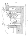
Figur 3 einen Ausschnitt der Synchronisiervorrichtung in Explosionsdarstellung gemäß den Linien 3 - 3 derFiguren 2, 4 bis 7, 9, 11 und 12;Figur 4 einen Querschnitt gemäß der Linie 4 - 4 in Figur 1;- Figur 5 einen Querschnitt gemäß der Linie 5 - 5 in Fig. 1 jedoch unter Weglassung der Schaltmuffe;
- Figur 6 die rechte Seitenansicht eines in
Figur 3 dargestellten Sperringes; - Figur 7 die linke Seitenansicht eines in
Figur 3 dargestellten konischen Elementes; Figur 8 in vergrößertem Maßstab einen Schnitt gemäß der Linie 8 - 8 in Figur 7;- Figur 9 eine rechte Seitenansicht eines in
Figur 3 dargestellten Anpreßtellers; Figur 10 in einer Darstellung gemäßFigur 8 einen Schnitt gemäß der Linie 10 - 10 in Figur 9;- Figur 11 eine linke Seitenansicht einer in
Figur 3 dargestellten Kupplungsreibscheibe; Figur 12 eine linke Seitenansicht einer inFigur 3 dargestellten Trennscheibe und- Figur 13 in vergrößertem Maßstab ein Detail der Figur 1 mit einer wahlweise vorzusehenden, zur Aufrechterhaltung eines Umlaufspiels dienenden Zugfeder zwischen den beiden Sperringen.
- 1 shows a longitudinal section through a synchronizing device according to the line 1 - 1 in Figures 4 and 5;
- Figure 2 on a reduced scale and partly in an exploded view in side view a sleeve carrier with a transmission device to a shift sleeve shown only in detail;
- 3 shows a section of the synchronizing device in an exploded view according to lines 3 - 3 of FIGS. 2, 4 to 7, 9, 11 and 12;
- Figure 4 shows a cross section along the line 4-4 in Figure 1;
- Figure 5 shows a cross section along the line 5-5 in Figure 1 but omitting the shift sleeve;
- Figure 6 is the right side view of a locking ring shown in Figure 3;
- FIG. 7 shows the left side view of a conical element shown in FIG. 3;
- FIG. 8 shows a section on an enlarged scale along the line 8-8 in FIG. 7;
- Figure 9 is a right side view of a pressure plate shown in Figure 3;
- FIG. 10 shows a section according to FIG. 8 along the line 10-10 in FIG. 9;
- Figure 11 is a left side view of a clutch friction disc shown in Figure 3;
- Figure 12 is a left side view of a cutting disc shown in Figure 3 and
- FIG. 13 shows, on an enlarged scale, a detail from FIG. 1 with an optionally provided tension spring between the two locking rings, which is used to maintain a clearance clearance.
Figur 1 zeigt eine Synchronisiervorrichtung 10 zur Synchronisierung zweier Rotationsteile 12,14 oder aber 12,64, die um eine gemeinsame Achse a-a rotieren. Die Vorrichtung besteht aus einem Muffenträger 16, der von dem ersten Rotationsteil 12 getragen wird und über eine Keilverzahnung 18 in Drehverbindung mit diesem ersten Rotationsteil 12 steht. Der insbesondere in Figur 2 dargestellte Muffenträger 16 weist einen gezahnten Außenumfang 20 auf, in dem zwei Gruppen von im gleichen Winkelabstand voneinander angeordneten Nuten 22,24 vorgesehen sind. Die Nuten 22 der ersten Gruppe sind flach ausgebildet und erstrecken sich über die volle Breite des Muffenträgers 16. Vorzugsweise sind drei derartiger Nuten 22 angeordnet. Auch von den Nuten 24 der zweiten Gruppe sind zumindest drei vorgesehen. Sie sind zwischen den Nuten 22 der ersten Gruppe angeordnet und haben eine erheblich größere Tiefe; sie erstrecken sich ebenfalls über die gesamte Breite des Muffenträgers 16.FIG. 1 shows a synchronizing
Im Boden jeder Nute 24 ist eine Bohrung 26 vorgesehen, die eine übertragungseinrichtung 28 aufnimmt. Letztere besteht jeweils aus einem Führungsstück 30, einem Kolben 32 und einer Feder 34. Diese übertragungseinrichtung erstreckt sich über den Muffenträger 16 hinaus und liegt an einer Schaltmuffe 36 an, die eine gezahnte innere Umfangsfläche 38 aufweist, die in die gezahnte Außenfläche 20 des Muffenträgers 16 eingreift. In dieser normalen Eingriffsstellung tauchen die Kolben 2 der Obertragungseinrichtung 28 in eine ringförmige Nut-37 ein (siehe Figur 3), die in der inneren Umfangsfläche 38 der Schaltmuffe 36 angeordnet ist. Die Kolben 32 werden in dieser Nut 37 sowohl von den Führungsstücken 30 als auch von den Federn 34 gehalten, die die Kolben nach außen drücken.A bore 26 is provided in the bottom of each
Die Schaltmuffe 36 weist ferner eine ringförmige Außenfläche 40 auf, die eine übliche, jedoch nicht dargestellte Schaltgabel aufzunehmen vermag, die zur Axialverschiebung der Schaltmuffe 36 mit Hilfe eines in der Fahrerkabine des Fahrzeugs angeordneten Handhebels dient. Die Verbindung des Handhebels mit der Schaltgabel sowie das Zusammenwirken mit der Schaltmuffe 36 sind einem Durchschnittsfachmann bekannt und werden daher nicht weiter erläutert.The
Gemäß Figur 1 ist auf beiden Seiten des Muffenträgers 16 jeweils ein Sperring 42,42' angeordnet. Die gemäß Figur 1 links vom Muffenträger 16 angeordneten Teile sind mit glatten Nummern, die entsprechenden, rechts vom Muffenträger 16 liegenden Teile mit der gleichen Nummer, jedoch mit einem zusätzlichen Strich bezeichnet. Jeder Sperring 42,42' , der am besten in den Figuren 3 und 6 erkennbar ist, weist eine konische innere Reibfläche 44 auf, die sich in Richtung auf den Muffenträger 16 radial verjüngt. Die Neigung beträgt etwa 5°bis 10°, vorzugsweise aber etwa 6,5°, gemessen von der Mittelachse des ersten Rotationsteiles 12. Auf einer zylindrischen Außenfläche 45,45' sind abgefaste Zähne 46, 46' angeordnet, deren Außendurchmesser etwa dem Innendurchmesser der inneren Umfangsfläche 38 der Schaltmuffe 36 entspricht. Daher können die Zähne der Schaltmuffe 36 in die Zähne des Sperrringes 42 oder aber 42' eingreifen, wenn die Schaltmuffe 36 axial über einen der beiden Sperringe verschoben wird. Zwischen der inneren Reibfläche 44 und der äußeren Mantelfläche 45 bzw. 44' ,45' sind Klauen 48 bzw. 48' angeordnet, die in die Nuten 22 des Muffenträgers 16 eingreifen und die Relativverdrehung zwischen Muffenträger 16 und Sperring 42,42' begrenzen. Jeder Sperrring 42,42' weist vorzugsweise soviele Klauen 48,48' auf, wie Nuten 22 im Muffenträger 16 vorgesehen sind.According to FIG. 1, a locking
Seitlich neben dem Sperring 42,42' sind jeweils gegenüber vom Muffenträger 16 Getrieberinge 50,50' angeordnet. Gemäß den Figuren 1, 3 und 4 ist der Getriebering 50 über eine Schweißnaht 51 mit dem zweiten Rotationsteil 14 verbunden, während gemäß Figur 1 der Getriebering 50' über eine Schweißnaht 51' mit dem dritten Rotationsteil 64 in gleicher Weise verbunden ist.Das zweite und dritte Rotationsteil 14,64 ist jeweils ein Zahnrad mit gezahnter Außenfläche 15 bzw. 66. Beide Rotationsteile 14,64 sitzen frei drehbar auf dem ersten Rotationsteil 12 und können unabhängig voneinander rotieren. Das zweite Rotationsteil 14 ist auf seiner linken Seite 59 durch eine Schulter 60 des ersten Rotationsteiles 12 und auf seiner rechten Seite durch den Muffenträger 16 axial festgelegt, der seinerseits gegen eine Axialverschiebung nach rechts durch einen Schnappring 62 festgelegt ist. Das dritte Rotationsteil 64 ist auf seiner rechten Seite 65 durch eine Haltebuchse 67 axial fixiert, die fest mit dem ersten Rotationsteil 12 verbunden ist, beispielsweise durch einen Preßsitz.The side of the locking
Gemäß den Figuren 1 und 3 weist der Getriebering 50 eine gezahnte Außenfläche 52 auf, deren Außendurchmesser etwa dem Innendurchmesser der inneren Umfangsfläche 38 der Schaltmuffe 36 entspricht. Letztere kann daher mit ihren Innenzähnen in die Zähne des Getrieberinges 50 eingreifen, wenn sie über den Sperring 42 hinweg auf den Getriebering 50 axial verschoben wird. Der Getriebering 50 weist ferner eine dem Muffenträger 16 zugewandte flache Seitenfläche 54 und zumindest eine Ausnehmung 56 auf (siehe Figur 1), die sich vorzugsweise durch den Getriebering 50 hindurch erstreckt. Vorzugsweise sind vier derartige Ausnehmungen 56 vorgesehen, die im gleichen Winkelabstand voneinander angeordnet sind. Der Getriebering 50' entspricht in seinem Aufbau dem Getriebering 50.According to FIGS. 1 and 3, the
Die Synchronisiervorrichtung 10 umfaßt ferner ein konisches Element 68, einen Anpreßteller 84, eine Kupplungsreibscheibe 102 sowie eine Trennscheibe 112, die jeweils paketweise auf beiden Seiten des Muffenträgers 16 zwischen Sperring 42,42' und Getriebering 50,50' angeordnet sind. Zur Vereinfachung werden lediglich die in Figur 1 bzw. 3 links vom Muffenträger 16 angeordneten Teile erläutert. Das konische Element 68 ist ein hohler Ring, der koaxial um das erste Rotationsteil 12 angeordnet ist und eine konische äußere Reibfläche 70, eine erste Seitenfläche 72 und abgetreppte zweite und dritte Seitenflächen 74,76 aufweist. Das konische Element 68 fluchtet mit dem Sperring 42 derart, daß dessen konische innere Reibfläche 44 die konische äußere Reibfläche 70 des konischen Elementes kraftschlüssig beaufschlagen kann, wenn der Sperring 42 axial gegen das konische Element 68 verschoben wird. Die erste Seitenfläche 72 des konischen Elementes 68 kann ferner eine Reibfläche 73 an der Seite des Muffenträgers 16 kraftschlüssig beaufschlagen. Die Reib- fläche 73 kann aus jedem bekannten Material mit einem hohen Reibungskoeffizienten bestehen.The synchronizing
Figur 7 zeigt eine linke Seitenansicht des konischen Elementes 68. Zu erkennen ist eine Gruppe von etwa zitronenförmig ausgebildeten Ausnehmungen 78 sowie eine Gruppe von schmalen, bogenförmig verlaufenden Schlitzen 79 in der zweiten Seitenfläche 74. Es sind zumindest drei, vorzugsweise aber vier derartige Ausnehmungen und Schlitze vorgesehen, die im gleichen Winkelabstand voneinander angeordnet sind. Die Ausnehmungen 78 haben im Querschnitt die Form eines flachen V (siehe Figur 8 ) mit jeweils zwei Auflaufschrägen 80, die sich gegenüberliegen und von der Seitenfläche 74 nach innen um etwa 10°bis 45° , vorzugsweise 20° bis 40°, bei optimaler Ausbildung aber um etwa 35° geneigt sind. Bezogen auf Figur 3 ragen die Auflaufschrägen 80 in die Bildebene hinein bzw. aus dieser Bildebene heraus und sind ausgerichtet auf die,Umlaufbewegung des konischen Elementes 68. Diese Auflaufschrägen 80 ermöglichen einen selbstverstärkenden Betrieb der Synchronisiervorrichtung 10 unabhängig davon, ob das konische Element 68 im Uhrzeigersinn oder entgegen rotiert.FIG. 7 shows a left side view of the
Die gegenüber den Ausnehmungen 78 etwas winkelversetzt angeordneten bogenförmig verlaufenden Schlitze 79 dienen zur teilweisen Aufnahme einer Zugfeder 81 (siehe untere Hälfte der Fig. 1), deren eines Ende in einer Ausnehmung 83 des konischen Elementes 68 und deren anderes Ende in einer entsprechenden Ausnehmung 85 im Anpreßteller 84 befestigt sind (siehe auch Figur 5). Vorzugsweise sind vier derartige Zugfedern 81 vorgesehen, die die beiden Teile 68,84 ständig gegeneinander ziehen.The
Das konische Element 68 weist ferner vorzugsweise vier Klauen 82 . auf, die zwischen der Stufe zwischen zweiter und dritter Seitenfläche 74,76 angeordnet sind und eine Axialverschiebung des Anpreßtellers 84 gegenüber dem konischen Element 68 ermöglichen.The
Der in den Figuren 1, 3 und 9 dargestellte Anpreßteller 84 umgreift das erste Rotationsteil 12 koaxial, liegt neben der zweiten Seitenfläche 74 des konischen Elementes 68 und weist eine erste und zweite Seitenfläche 86,88 und zumindest drei, vorzugsweise aber vier im gleichen Winkelabstand voneinander angeordnete Klauen 90 auf. Letztere ragen, wie Figur 1 erkennen läßt, von der zweiten Seitenfläche 88 in axialer Richtung und greifen in die entsprechenden Ausnehmungen 56 des Getrieberinges 50 ein. Die Breite jeder Klaue 90 entspricht etwa dem Durchmesser jeder Ausnehmung 56 (siehe Figur 4). Durch diese Klauenverbindung rotiert der Anpreßteller 84 synchron mit dem Getriebering 50. Durch die Länge jeder Klaue 90 kann der Anpreßteller 84 gegenüber dem Getriebering 50 eine Axialverschiebung ausüben.The
Gemäß Figur 9 sind in der ersten Seitenfläche 86 des Anpreßtellers 84 mehrere Ausnehmungen 92 vorgesehen, die hinsichtlich Anzahl, Formgebung und Anordnung den Ausnehmungen 78 im konischen Element 68 entsprechen. Figur 10 läßt erkennen, daß auch die Ausnehmungen 92 einen der Ausnehmung 78 entsprechenden Querschnitt mit sich gegenüberliegenden Auflaufschrägen 94 mit gleicher Winkelneigung aufweisen. In jedes Paar sich gegenüberliegender Ausnehmungen 78,92 greift eine Kugel 100 ein, deren Durchmesser größer ist als die doppelte Tiefe der Ausnehmung 78 bzw. 92. Dadurch weist die erste Seitenfläche 86 des Anpreßtellers 84 von der zweiten Seitenfläche 74 des konischen Elementes 68 immer einen gewissen Abstand auf. Sowie eine Relativrotation zwischen dem konischen Element 68 und dem Anpreßteller 84 auftritt, laufen die Kugeln 100 zwangsweise auf die Auflaufschrägen 80,94 ihrer Ausnehmungen 78,92 auf und bewirken dadurch eine axiale Verschiebung des konischen Elementes 68 gegenüber dem Anpreßteller 84. Gleichzeitig aber drücken die Kugeln 100 auch das konische Element 68 mit seiner ersten Seitenfläche 72 gegen die seitliche Reibfläche 73 des Muffenträgers 16. Diese auferzwungenen Axialverschiebungen ergeben sich unabhängig davon, ob'sich die Teile 68,84 im Uhrzeigersinn oder aber entgegen hierzu drehen. Die Kugeln 100 bewirken eine Selbstverstärkung beim Synchronisieren, was später noch im einzelnen erläutert wird.According to FIG. 9, a plurality of
Im Außenumfang des Anpreßtellers 84 sind zwei Gruppen von Nuten 96,98 vorgesehen. Die erste Gruppe umfaßt zumindest drei, vorzugsweise aber vier im gleichen Winkelabstand voneinander angeordnete Nuten 96, die neben den in der zweiten Seitenfläche 88 vorgesehenen öffnungen 85 liegen. Diese Nuten 96 korrespondieren mit den schmalen, bogenförmig ausgebildeten Schlitzen 79 des konischen Elementes 68 und nehmen teilweise die Zugfedern 81 auf. Die Enden dieser Zugfedern 81 sind in den entsprechenden Ausnehmungen 83,85 festgelegt, so daß die Achse jeder Feder 81 parallel zur Achse des ersten Rotationsteiles 12 liegt, wie die untere Hälfte der Figur 1 erkennen läßt. Die zweite Gruppe umfaßt zumindest drei, vorzugsweise aber vier Nuten 98, die die Klauen 82 des konischen Elementes 68 aufnehmen. Das Spiel zwischen Klauen 82 und Nuten 98 erlaubt eine Verdrehung des konischen Elementes 68 gegenüber dem Anpreßteller 84.Two groups of
Die Figuren 3 und 11 zeigen am besten die Kupplungsreibscheibe 102, die neben der zweiten Seitenwandung 88 des Anpreßtellers 84 liegt, ringförmig ausgebildet ist, das erste Rotationsteil 12 koaxial umgreift und eine gezahnte Innenfläche 104 aufweist, die in eine entsprechend gezahnte Außenfläche 106 des Muffenträgers 16 eingreift. Daher drehen Muffenträger 16 und Kupplungsreibscheibe 102 ständig synchron. Jedoch kann die Kupplungsreibscheibe 102 gegenüber dem Muffenträger 16 axial verschoben werden.FIGS. 3 and 11 best show the
Die Kupplungsreibscheibe 102 ist auf ihren beiden Seitenflächen mit einem Reibbelag 108,110 versehen. Der Reibbelag 108 beaufschlagt die zweite Seitenfläche 88 des Anpreßtellers 84, wenn die beiden Teile 84,102 axial gegeneinander geschoben werden, während der Reibbelag 110 die zwischen der Kupplungsreibscheibe 102 und der flachen Seitenfläche 54 des Getrieberinges 50 angeordnete Trennscheibe 112 beaufschlagt, wenn die beiden Teile 102,112 axial gegeneinander verschoben werden.The K
Die insbesondere in den Figuren 1,3,5 und 12 dargestellte Trennscheibe 112 hat die Form eines dünnen Ringes, der das erste Rotationsteil 12 koaxial umgreift und einen leicht gebogenen Außenumfang 114 aufweist, in dem zwei Gruppen von Nuten 116,118 angeordnet sind, die jeweils drei, vorzugsweise aber vier Nuten umfassen. Die Nuten 116 der ersten Gruppe bilden eine Durchtrittsöffnung für die Klauen 90 des Anpreßtellers 84, sind aber breiter ausgebildet als die Klauen 90, so daß der Anpreßteller 84 gegenüber der Trennscheibe 112 eine begrenzte Umdrehung ausführen kann, wenn die Kugeln 100 aus ihren Ausnehmungen austreten.The
Die Nuten 118 der zweiten Gruppe bilden öffnungen für die Klauen 82 des konischen Elementes (siehe Figur 5), so daß beim Zusammenbau der Synchronisiervorrichtung 10 der Außenumfang 114 der Trennscheibe 112 vollständig von dem konischen Element 68 umgriffen wird. Wie bei einer Keilverzahnung erlauben die Klauen 82 eine Axialverschiebung der Trennscheibe 112 gegenüber dem konischen Element 68, sorgen aber gleichzeitig für eine synchrone Drehung der Trennscheibe 112 mit dem konischen Element 68. Dadurch können die sich aus der Beaufschlagung zwischen Trennscheibe 112 und Kupplungsreibscheibe 102 ergebenden Reibungskräfte unmittelbar in das konische Element 68 eingespeist werden.The
Figur 13 zeigt wahlweise vorzusehende Zugfedern 120 zwischen den Sperringen 42,42'. Die drei, vorzugsweise aber vier Zugfedern 120 sind im gleichen Winkelabstand voneinander um den Muffenträger 16 herum angeordnet und ragen durch Bohrungen 122, die fluchtend miteinander durch die Sperringe 42,42' und den Muffenträger 16 führen. Die Enden 124,124' jeder Zugfeder 120 greifen in Ausnehmungen 126,126' ein, die in den äußeren Stirnflächen der beiden Sperringe 42,42' vorgesehen sind. Die Zugfedern 120 begrenzen die Axialverschiebung der beiden Sperringe 42,42' voneinander weg und verhindern dadurch Reibungsblockierkräfte, die zwischen der äußeren konischen Reibfläche 70,70' und den inneren konischen Reibflächen 44,44' der Teile 68,68' und 42,42' auftreten könnten.FIG. 13 shows tension springs 120 to be optionally provided between the locking rings 42, 42 '. The three, but preferably four tension springs 120 are arranged at the same angular distance from one another around the
Die dargestellte Synchronisiervorrichtung arbeitet wie folgt:
- Nachfolgend wird lediglich die Synchronisierung zwischen dem ersten und zweiten Rotationsteil 12,14 erläutert. Die Synchronisierung zwischen dem ersten und dritten Rotationsteil 12,64 erfolgt identisch mit der einzigen Ausnahme, daß die
Schaltmuffe 36 dann in axialer Richtung auf den Getriebering 50' anstelle des Getrieberinges 50 verschoben wird.
- Only the synchronization between the first and second
rotating parts rotary parts 12, 64 is identical with the only exception that theshift sleeve 36 is then moved in the axial direction onto the gear ring 50 'instead of thegear ring 50.
Unter Bezugnahme auf die Figuren 1 bis 5 wird der Vorgang der Synchronisierung beschrieben beginnend mit einer neutralen Stellung der Schaltmuffe 36, in der sie unmittelbar über dem Muffenträger 16 liegt, wie Figur 1 zeigt. Die Synchronisierung kann unabhängig von der Relativdrehung zwischen erstem und zweitem Rotationsteil 12,14 erfolgen.The process of synchronization is described with reference to FIGS. 1 to 5, starting with a neutral position of the
Die Figuren 1 und 3 lassen erkennen, daß Muffenträger 16, Schaltmuffe 36, Sperring 42 und Kupplungsreibscheibe 102 alle mit gleicher Geschwindigkeit und in gleicher Richtung rotieren wie das erste Rotationsteil 12. Denn der Muffenträger 16 ist über die Keilverzahnung 18 mit dem ersten Rotationsteil 12 verbunden; die Schaltmuffe 36 greift mit ihrer inneren gezahnten Umfangsfläche 38 in die gezahnte Außenfläche 20 des ersten Rotationsteiles 12 ein; der Sperring 42 greift mit seinen Klauen 48 in die Nuten 22 des Muffenträgers 16 ein; die Kupplungsreibscheibe 102 sitzt auf der Keilverzahnung 106 des Muffenträgers 16. Die übrigen Teile, nämlich konisches Element 68, Anpreßteller 84, Trennscheibe 112 sowie Getriebering 50 rotieren alle mit gleicher. Geschwindigkeit und in gleicher Richtung mit dem zweiten Rotationsteil 14. Denn der Getriebering 50 ist über die Schweißnaht 51 permanent mit dem zweiten Rotationsteil 14 verbunden; die Klauen 90 des Anpreßtellers 84 ragen durch die Nuten 116 der Trennscheibe 112 hindurch und greifen ständig in die Öffnungen 56 des Getrieberinges 50 ein; die Klauen 82 des konischen Elementes 68 tauchen in die Nuten 98 und 118 des Anpreßtellers 84 bzw. der Trennscheibe 112 ein.FIGS. 1 and 3 show that
Der Synchronisiervorgang beginnt, wenn dieSchaltmuffe 36 aus ihrer neutralen Stellung in Richtung auf das zweite Rotationsteil 14 verschoben wird. Hierbei biegt sich die Feder 34 der übertragungseinrichtung 28 (siehe Figur 2), damit die Oberseite des Kolbens 32 in der Ringnut 37 der Schaltmuffe 36 verharren kann. Durch die Verschwenkung der übertragungseinrichtung 28 auf den Federn 34 werden die Führungsstücke 30 in Kontakt gebracht mit der rechten Seite des Sperringes 42, auf den dadurch eine Axialkraft ausgeübt wird. Diese verschiebt den Sperring 42 um den Bruchteil eines Millimeters, so daß die innere konische Reibfläche 44 die äußere konische Reibfläche 70 des konischen Elementes 68 beaufschlagt. Sowie dies erfolgt, dreht sich der Sperring 42 und damit seine Zähne 46 geringfügig um etwa die halbe Dicke eines Zahnes, so daß die Zähne 46 des Sperringes 42 nicht mehr mit der gezahnten Innenfläche der Schaltmuffe 36 fluchten. Das Maß dieser Verdrehbewegung ergibt sich aus dem Spiel, das die Klauen 48 des Sperringes 42 in den Nuten 22 des Muffenträgers 16 haben. Diese Fehlausrichtung blockiert die Verschiebung der Schaltmuffe 36 über den Sperring 42 auf den Getriebering 50 solange, bis die beiden Rotationsteile 12,14 mit gleicher Geschwindigkeit rotieren.The synchronization process begins when the
Durch die kraftschlüssige Beaufschlagung des konischen Elementes 68 durch den Sperring 42 ergibt sich eine Rotationsdifferenz zwischen konischem Element 68 und Anpreßteller 84. Dieser Geschwindigkeitsunterschied zwingt die Kugeln 100 aus ihren Ausnehmungen 78,92 heraus auf die Auflaufschrägen 80,94, wodurch konisches Element 68 und Anpreßteller 84 axial um den Bruchteil eines Millimeters auseinandergedrückt werden. Dadurch gelangt die erste Seitenfläche 72 des konischen Elementes 68 in kraftschlüssige Anlage an die Reibfläche 73 des Muffenträgers 16. Gleichzeitig wird aber die zweite Seitenfläche 88 des Anpreßtellers 84 gegen den Reibbelag-108 der Kupplungsreibscheibe 102 gedrückt, was wiederum den Reibbelag 110 auf der anderen Seite der Kupplungsreibscheibe in kraftschlüssige Anlage an die Trennscheibe 112 bringt. Letztere speist die von der Kupplungsreibscheibe 102 übertragenen Reibungskräfte zurück in das konische Element 68 ein und zwar über den durch die Klauen 82 und die Nuten 118 gebildeten Formschluß. Dadurch erfährt das erste Rotationsteil 12 eine geringe Abbremsung, während das zweite Rotationsteil 14 etwas beschleunigt wird, bis beide Teile 12,14 die gleiche Geschwindigkeit aufweisen.The non-positive action of the
Die Drehmomentkräfte zwischen dem ersten und zweiten Rotationsteil 12,14 werden über drei separate unabhängige Wege übertragen: Der erste Weg wird gebildet von dem Getriebering 50 über den Anpreßteller 84, das konische Element 68, den Sperring 42 und den Muffenträger 16 auf das erste Rotationsteil 12. Der zweite Weg ergibt sich von dem Getriebering 50 über den Anpreßteller 84, die Kupplungsreibscheibe 102 und den Muffenträger 16 auf das erste Rotationsteil 12. Der dritte Weg erfolgt von dem Getriebering 50 über den Anpreßteller 84, das konische Element 68, den Reibbelag 73 und den Muffenträger 16 auf das erste Rotationsteil 12. Der zweite und dritte Weg bilden Sekundärwege, während der erste Weg den Primärweg darstellt.The torque forces between the first and second
Solange die Drehmomente zwischen dem ersten und zweiten Rotationsteil 12,14 übertragen werden, führt die geringe Axialverschiebung zwischen den verschiedenen Teilen dazu, daß sich das zweite Rotationsteil 14 mit seiner linken Seite 59 unter Kraftschluß gegen die Schulter 60 anlegt (siehe Figur 1). Dieser kraftschlüssige Kontakt unterstützt die Synchronisierung. Haben das erste und zweite Rotationsteil 12,14 die gleiche Rotations- .geschwindigkeit, und steht die gezahnte Innenfläche 38 der Schaltmuffe 36 mit den angefasten Zähnen 46 des Sperringes 42 in Kontakt, wird letzterer wieder in Ausrichtung gebracht mit den inneren Zähnen 38 der Schaltmuffe 36. Letztere kann nun über den Sperring 42 hinweg axial verschoben werden bis zum Eingriff mit der gezahnten Außenfläche 52 des Getrieberinges 50. In dieser Position verbindet die Schaltmuffe 36 den Muffenträger 16 formschlüssig mit dem Getriebering 50 und stellt somit eine mechanische Verbindung zwischen dem ersten und zweiten Rotationsteil 12,14 her.As long as the torques are transmitted between the first and second
Zur Aufhebung der Synchronisierung zwischen dem ersten und zweiten Rotationsteil 12,14 wird der Fahrer zuerst den Antrieb des ersten Rotationsteiles 12 aufheben beispielsweise durch Betätigung einer üblichen Kupplung und wird dann die Schaltmuffe 36 durch Betätigung des angelenkten Schalthebels nach rechts verschieben in die in Figur 3 dargestellte Position. Die gezahnte Innenfläche 38 der Schaltmuffe 36 gibt dadurch den Getriebering 50 frei und bewegt sich zurück über den Sperring 42. Das zweite Rotationsteil 14 mit dem daran befestigten Getriebering 50 kann dann mit einer unterschiedlichen Geschwindigkeit gegenüber dem ersten Rotationsteil 12 umlaufen und zwar abhängig von der Ausgangsbelastung und den Zwischenkräften. Sowie die Schaltmuffe 36 auch den Sperring 42 freigibt, wird auch der Kraftschluß zwischen den beiden konischen Flächen 44,70 aufgehoben, da auf sie keine Drehmomente mehr einwirken. In diesem Augenblick rotiert der Sperring 42 mit dem Muffenträger 16 über den Formschluß zwischen Klauen 48 und Nuten 22; das konische Element 68 beginnt erneut umzulaufen mit der Geschwindigkeit des Getrieberinges 50. Gleichzeitig rollen die Kugeln 100 zurück in ihre Ausnehmungen 78,82 und erlauben dadurch eine axiale Trennung des konischen- Elementes 68 von dem Reibbelag 73, des Anpreßtellers 84 vom Reibbelag 108, des Reibbelages 110 von der Trennscheibe 112 sowie der linken Seite 59 des zweiten Rotationsteils 14 von der Schulter 60. Die Kugeln 100 werden in den Boden der zugeordneten Ausnehmungen 78,92 gedrückt infolge der von den Federn 81 auf das konische Element 68 und den Anpreßteller84 ausgeübten Zugkräfte. Sind auch noch die Federn 120 zwischen.den beiden Sperringen 42,42' angeordnet, unterstützen sie die vorstehend genannte Trennbewegung dadurch, daß sie den Sperring 42 nach rechts ziehen und dadurch den Kraftschluß zwischen den beiden konischen Reibflächen 44,70 aufheben. Dies beendet den Trennvorgang, so daß das erste und zweite Rotationsteil 12,14 wieder unabhängig voneinander rotieren können.In order to cancel the synchronization between the first and second
Synchronisierung und die Aufhebung erfolgen innerhalb von Sekundenbruchteilen; die Axialverschiebung zwischen den einzelnen Teilen ist minimal.und beträgt beispielsweise nur den Bruchteil eines Millimeters.Synchronization and cancellation take place within fractions of a second; the axial displacement between the individual parts is minimal, and is, for example, only a fraction of a millimeter.
Für einen Durchschnittsfachmann ergeben sich aus vorstehenden Erläuterungen zahlreiche Möglichkeiten zur Abänderung und Modifizierung, die jedoch durch die Ansprüche mit umfaßt sein sollen.For an average person skilled in the art there are numerous possibilities for modification and modification from the above explanations, which, however, are intended to be included in the claims.
Claims (26)
gekennzeichnet durch folgende Merkmale:
characterized by the following features:
Priority Applications (1)
| Application Number | Priority Date | Filing Date | Title |
|---|---|---|---|
| AT82110052T ATE18086T1 (en) | 1981-11-13 | 1982-10-30 | SYNCHRONIZING DEVICE FOR SYNCHRONIZING TWO ROTARY PARTS ROTATING ABOUT A COMMON AXIS. |
Applications Claiming Priority (2)
| Application Number | Priority Date | Filing Date | Title |
|---|---|---|---|
| US321139 | 1981-11-13 | ||
| US06/321,139 US4413715A (en) | 1981-11-13 | 1981-11-13 | Self-energized synchronizer |
Publications (2)
| Publication Number | Publication Date |
|---|---|
| EP0086875A1 true EP0086875A1 (en) | 1983-08-31 |
| EP0086875B1 EP0086875B1 (en) | 1986-02-19 |
Family
ID=23249341
Family Applications (1)
| Application Number | Title | Priority Date | Filing Date |
|---|---|---|---|
| EP82110052A Expired EP0086875B1 (en) | 1981-11-13 | 1982-10-30 | Device for synchronising two parts rotatable about the same axis |
Country Status (12)
| Country | Link |
|---|---|
| US (1) | US4413715A (en) |
| EP (1) | EP0086875B1 (en) |
| JP (1) | JPS5888228A (en) |
| AR (1) | AR232035A1 (en) |
| AT (1) | ATE18086T1 (en) |
| AU (1) | AU547285B2 (en) |
| BR (1) | BR8206461A (en) |
| CA (1) | CA1186918A (en) |
| DE (1) | DE3269218D1 (en) |
| DK (1) | DK504182A (en) |
| ES (1) | ES517311A0 (en) |
| ZA (1) | ZA828296B (en) |
Cited By (1)
| Publication number | Priority date | Publication date | Assignee | Title |
|---|---|---|---|---|
| AT520296A4 (en) * | 2017-11-10 | 2019-03-15 | Avl Commercial Driveline & Tractor Eng Gmbh | SWITCHING DEVICE FOR A GEARBOX |
Families Citing this family (34)
| Publication number | Priority date | Publication date | Assignee | Title |
|---|---|---|---|---|
| WO1985001998A1 (en) * | 1983-10-26 | 1985-05-09 | Zahnradfabrik Friedrichshafen Ag | Lock synchronization device for gear-box |
| EP0302857B1 (en) * | 1986-03-21 | 1990-06-06 | ZF FRIEDRICHSHAFEN Aktiengesellschaft | Locking synchronization system for gearbox shift systems |
| US5054595A (en) * | 1986-03-21 | 1991-10-08 | Zahnradfabrik Friedrichshafen Ag | Locking synchronizing means for transmission shifts |
| JP2600674B2 (en) * | 1987-05-09 | 1997-04-16 | トヨタ自動車株式会社 | Synchronizer |
| JPH0619190B2 (en) * | 1987-05-20 | 1994-03-16 | トヨタ自動車株式会社 | Synchronizer |
| JPH01141235A (en) * | 1987-11-27 | 1989-06-02 | Kanzaki Kokyukoki Mfg Co Ltd | Synchronous meshing type clutch device |
| US4830159A (en) * | 1988-01-29 | 1989-05-16 | Deere & Company | Multi-disk synchronizer |
| US5078244A (en) * | 1990-12-24 | 1992-01-07 | Eaton Corporation | Self-energizing synchronizer |
| US5103952A (en) * | 1990-12-24 | 1992-04-14 | Eaton Corporation | Pre-engergizer for one-way synchronizer |
| US5097930A (en) * | 1990-12-24 | 1992-03-24 | Eaton Corporation | Pre-energizer for a synchronizer |
| US5078245A (en) * | 1990-12-24 | 1992-01-07 | Eaton Corporation | Self-energizing synchronizer with force limiting |
| US5092438A (en) * | 1990-12-24 | 1992-03-03 | Eaton Corporation | Synchronizer with self-energizing |
| US5086897A (en) * | 1990-12-24 | 1992-02-11 | Eaton Corporation | Pre-energizer pins for a synchronizer |
| US5161423A (en) * | 1990-12-24 | 1992-11-10 | Eaton Corporation | Self-energizing synchronizer for equalizing shift time and effort of a multi-ratio transmission |
| US5065855A (en) * | 1990-12-24 | 1991-11-19 | Eaton Corporation | Self-energizing splines for a synchronizer |
| US5092439A (en) * | 1990-12-24 | 1992-03-03 | Eaton Corporation | Synchronizer with deep splines & improved boost ramps |
| US5141087A (en) * | 1990-12-24 | 1992-08-25 | Eaton Corporation | Self-energizing synchronizer |
| USRE35796E (en) * | 1990-12-24 | 1998-05-19 | Eaton Corporation | Self-energizing synchronizer |
| US5111922A (en) * | 1990-12-24 | 1992-05-12 | Eaton Corporation | Pre-energizer for a synchronizer |
| US5135087A (en) * | 1991-01-16 | 1992-08-04 | New Venture Gear, Inc. | Dual-cone synchronizer with servo action |
| US5269400A (en) * | 1992-10-20 | 1993-12-14 | Borg-Warner Automotive, Inc. | Transmission synchronizer |
| JP2566649Y2 (en) * | 1992-12-22 | 1998-03-30 | 株式会社 神崎高級工機製作所 | Multi-speed transmission for work vehicles |
| GB9606170D0 (en) * | 1996-03-23 | 1996-05-29 | Eaton Corp | Synchronizer mechanism |
| US5735767A (en) * | 1996-10-21 | 1998-04-07 | New Venture Gear, Inc. | Add-on two-speed compounder |
| US6149543A (en) * | 1999-09-17 | 2000-11-21 | New Venture Gear, Inc. | Compounder assembly with controllable overrunning clutch |
| BR9907360A (en) * | 1999-11-12 | 2001-06-26 | Eaton Corp | Dual-action ring-type synchronizer |
| KR100482107B1 (en) * | 2002-09-02 | 2005-04-13 | 현대자동차주식회사 | synchronizer device of manual transmission |
| US20040198548A1 (en) * | 2003-04-04 | 2004-10-07 | Showalter Dan J. | Synchronizer having ball ramp actuator mechanism |
| DE102010046139A1 (en) * | 2010-09-14 | 2012-03-15 | Stromag Ag | Synchronization unit for a positive double clutch |
| US9683614B2 (en) * | 2014-01-29 | 2017-06-20 | Eaton Corporation | Transmission gear synchronizer blocker ring formed of a thermoplastic material |
| EP3287655B1 (en) * | 2016-08-23 | 2019-03-20 | Oerlikon Friction Systems (Germany) GmbH | Synchronisation unit and a wheel gear box for a vehicle |
| EP3287656B1 (en) * | 2016-08-23 | 2019-03-20 | Oerlikon Friction Systems (Germany) GmbH | Synchronisation unit and a wheel gear box for a vehicle |
| DE102017202713A1 (en) | 2017-02-20 | 2018-08-23 | Bayerische Motoren Werke Aktiengesellschaft | Manual transmission and method for switching a gearbox |
| CN107906141A (en) * | 2017-12-12 | 2018-04-13 | 郑州科技学院 | Suitable for the lock ring type synchronized and speed changer of new-energy automobile |
Citations (9)
| Publication number | Priority date | Publication date | Assignee | Title |
|---|---|---|---|---|
| DE738514C (en) * | 1939-08-17 | 1943-08-19 | Zahnradfabrik Friedrichshafen | Synchronization device for claw clutches |
| FR1332492A (en) * | 1962-08-29 | 1963-07-12 | Porsche Kg | Synchronization device for a gear change mechanism, in particular for motor vehicles |
| US3286801A (en) * | 1964-07-17 | 1966-11-22 | Dana Corp | Synchronizing clutch with multiple conical discs |
| US3386302A (en) * | 1966-05-02 | 1968-06-04 | Ford Motor Co | Multiple speed ratio, synchronized torque transmission mechanism |
| DE1284309B (en) * | 1966-06-21 | 1968-11-28 | Steyr Daimler Puch Ag | Gear shift and synchronizing clutch for gear change transmissions of motor vehicles |
| GB1137332A (en) * | 1965-05-03 | 1968-12-18 | Borg Warner | Synchronizer mechanism |
| DE1910884A1 (en) * | 1969-03-04 | 1970-09-10 | Zahnradfabrik Friedrichshafen | Synchronizing device for gear change transmission |
| DE1755457A1 (en) * | 1968-04-09 | 1971-05-06 | Michael Meyerle | Synchronizing and gear shifting device, especially for motor vehicle gearboxes |
| US4185725A (en) * | 1977-05-17 | 1980-01-29 | General Motors Corporation | Synchronizer arrangements for stepped-ratio transmissions |
Family Cites Families (5)
| Publication number | Priority date | Publication date | Assignee | Title |
|---|---|---|---|---|
| US2745529A (en) * | 1953-09-26 | 1956-05-15 | Volkswagenwerk Ag | Synchronizing gears |
| US2941641A (en) * | 1955-09-21 | 1960-06-21 | Daimler Benz Ag | Synchronizing clutch |
| DE1170795B (en) * | 1961-09-20 | 1964-05-21 | Porsche Kg | Synchronization device for speed change gears, especially for motor vehicles |
| DE2045383B2 (en) * | 1970-09-14 | 1971-12-09 | Carl Hurth Maschinen und Zahnrad fabrik, 8000 München | SWITCHING DEVICE FOR A FRICTION CLUTCH |
| JPS4915861A (en) * | 1972-06-13 | 1974-02-12 |
-
1981
- 1981-11-13 US US06/321,139 patent/US4413715A/en not_active Expired - Fee Related
-
1982
- 1982-10-07 AU AU89200/82A patent/AU547285B2/en not_active Ceased
- 1982-10-30 EP EP82110052A patent/EP0086875B1/en not_active Expired
- 1982-10-30 AT AT82110052T patent/ATE18086T1/en not_active IP Right Cessation
- 1982-10-30 DE DE8282110052T patent/DE3269218D1/en not_active Expired
- 1982-11-03 CA CA000414752A patent/CA1186918A/en not_active Expired
- 1982-11-08 BR BR8206461A patent/BR8206461A/en unknown
- 1982-11-11 ZA ZA828296A patent/ZA828296B/en unknown
- 1982-11-12 DK DK504182A patent/DK504182A/en not_active Application Discontinuation
- 1982-11-12 AR AR291282A patent/AR232035A1/en active
- 1982-11-12 ES ES517311A patent/ES517311A0/en active Granted
- 1982-11-13 JP JP57199655A patent/JPS5888228A/en active Pending
Patent Citations (9)
| Publication number | Priority date | Publication date | Assignee | Title |
|---|---|---|---|---|
| DE738514C (en) * | 1939-08-17 | 1943-08-19 | Zahnradfabrik Friedrichshafen | Synchronization device for claw clutches |
| FR1332492A (en) * | 1962-08-29 | 1963-07-12 | Porsche Kg | Synchronization device for a gear change mechanism, in particular for motor vehicles |
| US3286801A (en) * | 1964-07-17 | 1966-11-22 | Dana Corp | Synchronizing clutch with multiple conical discs |
| GB1137332A (en) * | 1965-05-03 | 1968-12-18 | Borg Warner | Synchronizer mechanism |
| US3386302A (en) * | 1966-05-02 | 1968-06-04 | Ford Motor Co | Multiple speed ratio, synchronized torque transmission mechanism |
| DE1284309B (en) * | 1966-06-21 | 1968-11-28 | Steyr Daimler Puch Ag | Gear shift and synchronizing clutch for gear change transmissions of motor vehicles |
| DE1755457A1 (en) * | 1968-04-09 | 1971-05-06 | Michael Meyerle | Synchronizing and gear shifting device, especially for motor vehicle gearboxes |
| DE1910884A1 (en) * | 1969-03-04 | 1970-09-10 | Zahnradfabrik Friedrichshafen | Synchronizing device for gear change transmission |
| US4185725A (en) * | 1977-05-17 | 1980-01-29 | General Motors Corporation | Synchronizer arrangements for stepped-ratio transmissions |
Cited By (2)
| Publication number | Priority date | Publication date | Assignee | Title |
|---|---|---|---|---|
| AT520296A4 (en) * | 2017-11-10 | 2019-03-15 | Avl Commercial Driveline & Tractor Eng Gmbh | SWITCHING DEVICE FOR A GEARBOX |
| AT520296B1 (en) * | 2017-11-10 | 2019-03-15 | Avl Commercial Driveline & Tractor Eng Gmbh | SWITCHING DEVICE FOR A GEARBOX |
Also Published As
| Publication number | Publication date |
|---|---|
| ES8400811A1 (en) | 1983-11-01 |
| BR8206461A (en) | 1983-09-27 |
| ES517311A0 (en) | 1983-11-01 |
| AU547285B2 (en) | 1985-10-10 |
| DE3269218D1 (en) | 1986-03-27 |
| US4413715A (en) | 1983-11-08 |
| AR232035A1 (en) | 1985-04-30 |
| EP0086875B1 (en) | 1986-02-19 |
| ZA828296B (en) | 1984-06-27 |
| DK504182A (en) | 1983-05-14 |
| ATE18086T1 (en) | 1986-03-15 |
| CA1186918A (en) | 1985-05-14 |
| JPS5888228A (en) | 1983-05-26 |
| AU8920082A (en) | 1983-05-19 |
Similar Documents
| Publication | Publication Date | Title |
|---|---|---|
| EP0086875B1 (en) | Device for synchronising two parts rotatable about the same axis | |
| DE2512248C3 (en) | Locking synchronization device for a gearbox | |
| DE3622464C1 (en) | ||
| DE1630426B2 (en) | LOCKABLE DIFFERENTIAL GEAR E FOR VEHICLES | |
| EP0184077A1 (en) | Synchronising device for clutches | |
| EP0157908B1 (en) | Synchronizing device for shift clutches | |
| DE3324355C2 (en) | Centrifugal clutch | |
| DE2949194C2 (en) | Mechanical switching device for a motor vehicle change gearbox | |
| EP0328910B1 (en) | Synchronising arrangement for synchronised transmission | |
| EP0248899B1 (en) | Multi-step gear-box | |
| DE19543645B4 (en) | Device for switching lock-synchronized vehicle transmissions | |
| DE2751699C3 (en) | Device for the noiseless switching of a reverse gear of speed change gears, in particular of motor vehicles | |
| DE102007022544B4 (en) | Clutch arrangement | |
| DD295700A5 (en) | ONE-WAY CLUTCH | |
| DE2815202A1 (en) | MANUAL TRANSMISSION | |
| DE2706661A1 (en) | Synchromesh for vehicle gear box - has locking assembly connecting two synchro rings into one axially slidable unit | |
| DE2848288C2 (en) | ||
| DE3729818C2 (en) | ||
| DE4038731C2 (en) | Coupling device for connecting two shafts rotating at different speeds | |
| DE3623142C2 (en) | ||
| DE60108933T2 (en) | synchronizer | |
| DE2820774C2 (en) | Synchronizing device for manual transmissions | |
| DE925443C (en) | Synchronizer | |
| EP0727599B1 (en) | Shift device for a gearbox | |
| DE3009853B1 (en) | Centrifugal clutch |
Legal Events
| Date | Code | Title | Description |
|---|---|---|---|
| PUAI | Public reference made under article 153(3) epc to a published international application that has entered the european phase |
Free format text: ORIGINAL CODE: 0009012 |
|
| AK | Designated contracting states |
Designated state(s): AT BE DE FR GB IT NL SE |
|
| 17P | Request for examination filed |
Effective date: 19830727 |
|
| ITCL | It: translation for ep claims filed |
Representative=s name: LENZI & C. |
|
| EL | Fr: translation of claims filed | ||
| TCNL | Nl: translation of patent claims filed | ||
| ITF | It: translation for a ep patent filed |
Owner name: LENZI & C. |
|
| GRAA | (expected) grant |
Free format text: ORIGINAL CODE: 0009210 |
|
| AK | Designated contracting states |
Designated state(s): AT BE DE FR GB IT NL SE |
|
| REF | Corresponds to: |
Ref document number: 18086 Country of ref document: AT Date of ref document: 19860315 Kind code of ref document: T |
|
| REF | Corresponds to: |
Ref document number: 3269218 Country of ref document: DE Date of ref document: 19860327 |
|
| ET | Fr: translation filed | ||
| PGFP | Annual fee paid to national office [announced via postgrant information from national office to epo] |
Ref country code: AT Payment date: 19861015 Year of fee payment: 5 |
|
| PGFP | Annual fee paid to national office [announced via postgrant information from national office to epo] |
Ref country code: NL Payment date: 19861031 Year of fee payment: 5 |
|
| PLBE | No opposition filed within time limit |
Free format text: ORIGINAL CODE: 0009261 |
|
| STAA | Information on the status of an ep patent application or granted ep patent |
Free format text: STATUS: NO OPPOSITION FILED WITHIN TIME LIMIT |
|
| 26N | No opposition filed | ||
| PG25 | Lapsed in a contracting state [announced via postgrant information from national office to epo] |
Ref country code: AT Effective date: 19871030 |
|
| PG25 | Lapsed in a contracting state [announced via postgrant information from national office to epo] |
Ref country code: SE Effective date: 19871031 Ref country code: BE Effective date: 19871031 |
|
| BERE | Be: lapsed |
Owner name: DEERE & CY Effective date: 19871031 |
|
| PG25 | Lapsed in a contracting state [announced via postgrant information from national office to epo] |
Ref country code: NL Effective date: 19880501 |
|
| NLV4 | Nl: lapsed or anulled due to non-payment of the annual fee | ||
| GBPC | Gb: european patent ceased through non-payment of renewal fee | ||
| PG25 | Lapsed in a contracting state [announced via postgrant information from national office to epo] |
Ref country code: FR Free format text: LAPSE BECAUSE OF NON-PAYMENT OF DUE FEES Effective date: 19880630 |
|
| REG | Reference to a national code |
Ref country code: FR Ref legal event code: ST |
|
| PG25 | Lapsed in a contracting state [announced via postgrant information from national office to epo] |
Ref country code: GB Effective date: 19881122 |
|
| PG25 | Lapsed in a contracting state [announced via postgrant information from national office to epo] |
Ref country code: DE Effective date: 19900703 |
|
| EUG | Se: european patent has lapsed |
Ref document number: 82110052.6 Effective date: 19880712 |