EP0086383A2 - Appareils à sorption et procédé pour leur mise en oeuvre - Google Patents
Appareils à sorption et procédé pour leur mise en oeuvre Download PDFInfo
- Publication number
- EP0086383A2 EP0086383A2 EP83100852A EP83100852A EP0086383A2 EP 0086383 A2 EP0086383 A2 EP 0086383A2 EP 83100852 A EP83100852 A EP 83100852A EP 83100852 A EP83100852 A EP 83100852A EP 0086383 A2 EP0086383 A2 EP 0086383A2
- Authority
- EP
- European Patent Office
- Prior art keywords
- heat
- sorption apparatus
- sorption
- heat exchanger
- brine
- Prior art date
- Legal status (The legal status is an assumption and is not a legal conclusion. Google has not performed a legal analysis and makes no representation as to the accuracy of the status listed.)
- Withdrawn
Links
Images

Classifications
-
- F—MECHANICAL ENGINEERING; LIGHTING; HEATING; WEAPONS; BLASTING
- F25—REFRIGERATION OR COOLING; COMBINED HEATING AND REFRIGERATION SYSTEMS; HEAT PUMP SYSTEMS; MANUFACTURE OR STORAGE OF ICE; LIQUEFACTION SOLIDIFICATION OF GASES
- F25B—REFRIGERATION MACHINES, PLANTS OR SYSTEMS; COMBINED HEATING AND REFRIGERATION SYSTEMS; HEAT PUMP SYSTEMS
- F25B35/00—Boiler-absorbers, i.e. boilers usable for absorption or adsorption
- F25B35/04—Boiler-absorbers, i.e. boilers usable for absorption or adsorption using a solid as sorbent
-
- F—MECHANICAL ENGINEERING; LIGHTING; HEATING; WEAPONS; BLASTING
- F25—REFRIGERATION OR COOLING; COMBINED HEATING AND REFRIGERATION SYSTEMS; HEAT PUMP SYSTEMS; MANUFACTURE OR STORAGE OF ICE; LIQUEFACTION SOLIDIFICATION OF GASES
- F25B—REFRIGERATION MACHINES, PLANTS OR SYSTEMS; COMBINED HEATING AND REFRIGERATION SYSTEMS; HEAT PUMP SYSTEMS
- F25B17/00—Sorption machines, plants or systems, operating intermittently, e.g. absorption or adsorption type
- F25B17/08—Sorption machines, plants or systems, operating intermittently, e.g. absorption or adsorption type the absorbent or adsorbent being a solid, e.g. salt
-
- F—MECHANICAL ENGINEERING; LIGHTING; HEATING; WEAPONS; BLASTING
- F25—REFRIGERATION OR COOLING; COMBINED HEATING AND REFRIGERATION SYSTEMS; HEAT PUMP SYSTEMS; MANUFACTURE OR STORAGE OF ICE; LIQUEFACTION SOLIDIFICATION OF GASES
- F25B—REFRIGERATION MACHINES, PLANTS OR SYSTEMS; COMBINED HEATING AND REFRIGERATION SYSTEMS; HEAT PUMP SYSTEMS
- F25B29/00—Combined heating and refrigeration systems, e.g. operating alternately or simultaneously
- F25B29/006—Combined heating and refrigeration systems, e.g. operating alternately or simultaneously of the sorption type system
-
- F—MECHANICAL ENGINEERING; LIGHTING; HEATING; WEAPONS; BLASTING
- F25—REFRIGERATION OR COOLING; COMBINED HEATING AND REFRIGERATION SYSTEMS; HEAT PUMP SYSTEMS; MANUFACTURE OR STORAGE OF ICE; LIQUEFACTION SOLIDIFICATION OF GASES
- F25B—REFRIGERATION MACHINES, PLANTS OR SYSTEMS; COMBINED HEATING AND REFRIGERATION SYSTEMS; HEAT PUMP SYSTEMS
- F25B49/00—Arrangement or mounting of control or safety devices
- F25B49/04—Arrangement or mounting of control or safety devices for sorption type machines, plants or systems
- F25B49/046—Operating intermittently
-
- Y—GENERAL TAGGING OF NEW TECHNOLOGICAL DEVELOPMENTS; GENERAL TAGGING OF CROSS-SECTIONAL TECHNOLOGIES SPANNING OVER SEVERAL SECTIONS OF THE IPC; TECHNICAL SUBJECTS COVERED BY FORMER USPC CROSS-REFERENCE ART COLLECTIONS [XRACs] AND DIGESTS
- Y02—TECHNOLOGIES OR APPLICATIONS FOR MITIGATION OR ADAPTATION AGAINST CLIMATE CHANGE
- Y02A—TECHNOLOGIES FOR ADAPTATION TO CLIMATE CHANGE
- Y02A30/00—Adapting or protecting infrastructure or their operation
- Y02A30/27—Relating to heating, ventilation or air conditioning [HVAC] technologies
-
- Y—GENERAL TAGGING OF NEW TECHNOLOGICAL DEVELOPMENTS; GENERAL TAGGING OF CROSS-SECTIONAL TECHNOLOGIES SPANNING OVER SEVERAL SECTIONS OF THE IPC; TECHNICAL SUBJECTS COVERED BY FORMER USPC CROSS-REFERENCE ART COLLECTIONS [XRACs] AND DIGESTS
- Y02—TECHNOLOGIES OR APPLICATIONS FOR MITIGATION OR ADAPTATION AGAINST CLIMATE CHANGE
- Y02B—CLIMATE CHANGE MITIGATION TECHNOLOGIES RELATED TO BUILDINGS, e.g. HOUSING, HOUSE APPLIANCES OR RELATED END-USER APPLICATIONS
- Y02B30/00—Energy efficient heating, ventilation or air conditioning [HVAC]
Definitions
- the invention relates to sorption apparatus according to the preamble of claims 1 and 7 22 and methods for their operation.
- thermodynamic foundations of sorption devices have been known for the past century.
- the advantage of these continuous sorption devices is that the total power factor can be increased to values of up to 1.3, which can be achieved by avoiding energy losses in the power plant.
- heat pumps differ from cooling machines or sorption cooling devices in the field of application. Refrigerators are required to have an uninterrupted cooling effect at a constant cooling level. Since the waste heat is only used in the rarest of cases, its quantity and temperature are of no interest.
- the performance figures achieved with these devices are 1.3 according to the manufacturer's information. In practical use, at low heat source temperatures, fluctuating useful heat requirements or even in These performance figures are not achievable in cyclical operation.
- apparatuses of this type are designed for a medium useful heat output, which require additional heating in the case of a higher useful heat requirement. This means double investment and floor space, since the additional device must be designed for the maximum useful heat requirement.
- DE-OS 25 23 429 suggests storing heat from the heat source in a storage mass in order to then raise it to a useful heat storage unit by means of an electrically operated compressor heat pump, using reduced night electricity.
- Such proposals generally fail due to the size of the storage tank, since at the low useful heat temperatures, in addition to the required degree of roughness in the heat exchangers of the storage tank, an effective temperature spread of the storage mass is hardly possible.
- the "night-time electricity heat accumulator" which is operated using low-tariff electricity, represents a heat accumulator that has been tried and tested for decades.
- a storage mass In low-load periods, a storage mass is heated to temperatures above 600 ° C.
- the useful heat requirement is covered outside the low tariff period from the specific heat of the storage mass.
- the high storage temperatures lead to high heat losses. A heat pump effect is not possible.
- EP-OS 00 262 557 describes a batch sorption memory with the aim of storing the drive energy for a heat pump at sufficiently high temperatures.
- the structure of the sorption storage remains open, storage of the heat from a heat source is not provided.
- Two "sorption stores" are required for "quasi-continuous operation”.
- DE-PS 596 308 describes a device for the production of hot water by condensation or absorption in a batch-type absorption refrigeration apparatus.
- a thermostat control allows warm water to run unused so as not to impair the cooling effect.
- the invention has for its object to design sorption apparatus and to provide methods for their operation that they can be used simultaneously as a heat pump and heat storage.
- Heat from a heat source should be raised to the useful heat temperature by the heat pump effect and be storable together with the desorption heat required for the drive.
- the release of useful heat should be completely independent of the operating phases of the sorption apparatus.
- the teaching according to claim 6 simplifies the control effort to a minimum.
- the sorbent temperature increases by sorption, or in the desorption phase by heating, or with reduced useful heat demand
- the liquid column of the heat transfer medium sinks due to an increase in pressure in the heat exchanger device, or disappears entirely.
- the condenser temperature then drops because less working fluid vapor flows into the condenser.
- the pressure in the evaporator device 11 also decreases until the heat output regulator compensates for the pressure again by supplying heat transfer medium.
- the advantage of claim 8 is that the useful heat from the stove adsorber is released from the condenser to the consumer during the cooling and sorption phase. An additional heat exchanger at the consumer is not necessary, as is a separate regulation for the dissipation of this useful heat.
- the stove adsorber is separated from the condenser during the sorption phase.
- Claim 12 contains a number of further advantages.
- the splitting of the cooker adsorber into several cooker adsorber units enables easy transport of light and compact components to the installation site, convenient installation and flexible adaptation to the local space conditions.
- any desired storage size can be created in stages from standard-made cooker adsorber units.
- the individual stove adsorber units can only be filled with the pair of sorbents after they have been installed.
- any number of cooker adsorber units can advantageously remain in the rest position at all times of operation, or can be shut down entirely (for example in summer) if desired.
- zeolite / water to be advantageously used as the pair of adsorbents.
- zeolites those are particularly suitable which have a high water absorption capacity in conjunction with high thermal stability with a sufficient reduction in vapor pressure.
- Zeolites in powder and granule form are commercially available. Optimal performance figures are achieved with zeolites without or with binder contents below 18% by weight.
- the poor thermal conductivity in the zeolite can be improved according to the invention by processing the zeolite into solidified shapes with the lowest binder content, the shapes of the heat exchanger surfaces being reproduced or firmly bonded to them that will. Suitable flow channels must be provided to keep the pressure drop of the incoming and outgoing water vapor as low as possible.
- the zeolites do not swell due to the adsorption. This makes it possible to firmly embed the heat exchanger device in the zeolite layer.
- the zeolite and the heat exchanger device thus form a solid, stable unit, which makes vacuum-proof container walls superfluous. Both the heat exchanger and the stove adsorber jacket only have to seal the zeolite in a vacuum-tight manner. External pressure, e.g. B. air pressure, the heat exchanger device can thus press the zeolite and further improve the heat transfer.
- the zeolite / water pair also has the particular advantage that it is completely non-toxic and non-flammable. It shows no corrosion compared to sheet steel. If the useful heat temperature remains below 100 ° C, the entire system is in the negative pressure range. Costly pressure vessels, warning devices and overpressure safeguards are therefore unnecessary.
- the superheated working fluid vapor from the cooker adsorber is to be conducted during the desorption phase, before passing through the shut-off element, via sections of heat not directly heated by primary energy, and therefore still colder.
- the working fluid vapor cools down while the sorbent is degassed. The result is a significant increase in the performance figure.
- the teaching according to claim 22 has the advantage that expensive and large-volume steam shutoff devices can be dispensed with.
- the liquid valves on the vapor space can also be inexpensively designed as a check valve or float valve.
- the brine liquid controller according to claim 23 has the particular advantage that the coupling of the heat from the heat source is carried out completely independently of the useful heat. Only the heat source temperature at the end of the sorption phase is decisive for the effective power factor, not the temperatures beforehand. Strong fluctuations in the heat source temperature therefore have no influence on the current useful heat output or its temperature. A sudden increase in the brine liquid temperature and the working fluid pressure, e.g. B. by warm waste water from a cooling process, can only respond to the brine liquid controller.
- the split design of the evaporator device according to claim 22 and 25 in a vapor space, in which the actual evaporation takes place, and in at least one heat-absorbing heat exchanger, has the advantage of short working agent steam paths with an unrestricted choice of heat sources.
- At least one heat exchanger can always be installed at the location of the heat source or can itself take on the function of a heat collector (solar absorber, absorber roof, etc.). If air is used as a heat source, it does not have to be conducted to the evaporator via large-volume and energy-consuming flow channels.
- Claim 27 makes it possible to couple heat into the sorption apparatus even at heat source temperatures below 0 ° C.
- the advantages of claim 28 are, on the one hand, an extremely low vapor pressure of the admixed substance and, on the other hand, an equality of metal cations in the zeolite and in the brine liquid. If the brine liquid should ever come into contact with the zeolite, this does not lead to harmful ion exchange.
- the teaching according to claims 29, 30 and 31 has the advantage that the evaporation pressure in the vapor space at temperatures above the solidification limit is not unnecessarily reduced by excessive antifreeze concentrations.
- part of the brine liquid is stored in a detachable branch of the brine circuit, while liquid working fluid is replenished from the storage tank by a refill device into the brine circuit. In this way, even after the teaching of claim 26, the vaporized working fluid is readjusted.
- the teaching according to claim 33 is even more favorable for the performance figure if this amount of heat in the vapor space is transferred to the cold working fluid vapor. This does not unnecessarily derive its share of specific heat from the amount of useful heat.
- the combination of the evaporator and heat exchanger device according to the invention enables the working fluid vapor generated in the vapor space to be adsorbed via sorbent portions lines that are saturated under the given conditions, but cool down and continue to sorb due to the cooler working fluid vapor. It is thus not only possible to obtain the amount of heat for overheating the working fluid vapor in an energetically favorable manner, but also to improve the heat transfer from the sorbent to the heat exchanger device with temperature differences which are already becoming smaller due to flowing steam.
- the teaching according to claim 35 has the particular advantage that the entire sorption apparatus can be pumped out via a water jet pump. Disturbing gases that prevent the adsorption of working fluid vapor in the sorbent are entrained and compressed by the working fluid vapor flowing into the condenser. In contrast to refrigeration devices, which emit the waste heat at lower temperatures and pressures, the condenser pressure is high enough to remove the disruptive gases with a water jet pump.
- the metal plate from claim 36 can act as an excess pressure valve.
- the opening can advantageously be used for filling and inspection of the K o-cheradsorbers.
- the useful heat output is thereby independent of the desorption heat output.
- the performance figure is improved in that the heat transfer medium is not unnecessarily evaporated by heat of desorption.
- Claims 42, 57 and 58 all lead to a wider range of degassing and thus to a higher performance figure.
- the storage capacity is also increased indirectly, since the amount of useful heat is increased despite identical desorption heat expenditure.
- the sorbent temperature is reduced while increasing the degassing width.
- the heat losses through the insulation are reduced considerably.
- a possible reduction in the insulation strength leads to investment savings while at the same time reducing the space requirement.
- the method according to claim 44 initially has the same advantage as claim 43.
- the sorbent can sorb more working fluid at the same working fluid vapor pressure and thereby increase the amount of useful heat.
- the method according to claim 45 differs from the previous one in that the sorbent temperature can also drop far below the useful heating temperature.
- the well-known principle of two-stage can be achieved in the simplest way.
- the heat from the heat source is raised to the useful heat temperature level using two temperature levels. In contrast to the known ⁇ methods, this even significantly increases the storage capacity and the performance figure and does not reduce it.
- the teaching from claim 46 extends the method according to claim 45 to the general multi-stage.
- Claim 47 also leads to an increase in the performance figure, since the amount of heat transferred is part of the desorption heat.
- heating can be carried out electrically at low tariff times.
- the amount of useful heat available thereby increases only the pure amount of sorption heat.
- the method according to claim 49 also advantageously uses this pure amount of sorption heat without reheating electrically.
- the operating costs are reduced according to claim 50 by the fact that similar to the night stream tariff for (other) sales valleys such.
- Weekend electricity lower prices are possible, since these devices do not need peak electricity and the base load power plants can also be operated on weekends. Despite increased electricity sales, the construction of new power plants is not necessary. Hard coal-fired power plants can also be operated on weekends, thereby replacing oil in oil heating systems.
- the particular advantage of claim 52 lies in the fact that heat from the heat source can be coupled into the system completely independently of the operating states of the sorption apparatus. All forms of waste heat from industry, trade or household can be used without intermediate storage, even in the case of strongly fluctuating temperatures. The incineration of waste can also be used sensibly. Another previously unused heat source is the motor vehicle. The specific heat of the hot engine block can be transferred to the sorption apparatus via the cooling water circuit without a large additional investment. For this purpose, the vehicle parked after a journey is connected to a heat exchanger of the evaporator device via a quick coupling.
- the consumer can draw useful heat from the condenser or give off heat to the brine circuit.
- a heating circuit of the consumer thus becomes a cooling circuit.
- a conventional heating network can become an air conditioning system.
- the heat to be dissipated in the condenser can advantageously, for. B. serve to heat the swimming pool. If the condenser is not bypassed and a cooling effect is dispensed with, the same advantages result as in the method from claim 49.
- the vapor space becomes a condenser by this method, since working medium condenses from the sorbent into the brine liquid and heats it up in the process.
- the brine circuit can therefore be used for both cooling and heating.
- the heat released here can advantageously according to the teaching of claim 56 z. B. stored in an earth collector, ice storage, etc.
- the sorption apparatus according to claim 61 can be used with great advantage for the combustion of solid materials (e.g. wood, straw, paper, waste, etc.).
- the burner operating time is reduced to about a quarter of the usual burn time.
- a solid fuel burner only has to be refilled once a day or a week because the burning time does not have to be interrupted. The rest of the time, the sorption device takes care of the useful water supply. If the useful heat output is not increased, the burner can bring in about 3 times the output. Therefore, even with the smallest heating capacities, larger burners can be used, which have a higher efficiency and less pollutant emissions without partial load or cycle operation.
- Open fireplaces and tiled stoves can also be particularly advantageously coupled with a sorption device.
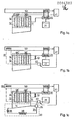
- 1 c shows the basic structure of the sorption apparatus according to the invention.
- a cooker adsorber 10 known per se contains a sorbent 12 and a heat exchanger device 11 in its upper part. According to the invention, in its lower part there is a vapor space 14 which is also part of the evaporator device 30.
- the evaporator device 30 is here a type of circulation evaporator with a separate vapor chamber 14 and heat exchanger 38 which is known per se. According to the invention, useful heat is also released to a consumer 50.
- a heat release controller 41 acting on an engagement element 40, regulates the operating states of the cooker adsorber 10 '. completely independent, the heat transfer into a condenser 20.
- An additional shut-off device 13 allows the coupling of heat from a heat source via the heat exchanger 38 into the cooker adsorber 10 during the sorption phase.
- a further heat transfer point 60 at the consumer 50 (shown in broken lines in FIG. 1c) can therefore be omitted.
- a storage tank 21, a refill device 34 and a brine pump 36 are also provided for operating the sorption
- FIGS. 1a-c To simplify the illustration, only the components required for operation or the components previously operated are shown in FIGS. 1a-c, starting from the desorption phase 1a.
- the operation of the sorption apparatus consists of three phases (Fig. 1).
- Working medium evaporates from a brine circuit 35 in the vapor space 14 at low temperatures and flows into the sorbent 12, where it is sorbed at higher temperatures and releases its heat of sorption.
- the cooled brine liquid is warmed up in the heat exchanger 38 and passed again into the vapor space 14.
- the working fluid evaporated in the vapor space 14 is filled up beforehand in the refill device 34 from the storage tank 21.
- the sorption heat is conducted to the consumer 50 in this phase in the same way as in the cooling phase.
- FIG. 1c shows, in addition to FIG. 1c, the connection of a plurality of stove adsorber units.
- the heat exchanger devices 11, 11a are equipped with an electrical heater 17, 17a. Only sorbent parts 16, 16a in front of the shut-off elements 13, 13a are not heated.
- the condenser 20 and a water jet pump 22 are connected upstream of the storage tank 21 on the heat emission side.
- the heat release controller 41 regulates the outlet to the heat exchanger devices 11, 11a via the engagement member 40.
- a working medium line leads from here to the evaporator device 30, which according to the invention contains a brine circuit 35 with a lockable branch 33, the refill device 34 and the brine pump 36.
- This circuit is connected to the vapor spaces 14, 14a via liquid valves 18, 18a and 19, 19a and a brine liquid regulator 37.
- the two cooker adsorber units 10 and 10a are connected via the two working medium steam lines 42 and 44.
- the sorbent 12 is preferably heated by the electric heater 17 during the low tariff times.
- the released working fluid vapor increases the pressure in the knockout cheradsorber 10 to above the condenser pressure. Now the shut-off device 13 can release the steam line to the condenser 20.
- the water jet pump 22 removes the non-condensable gases from the condenser 20.
- the shut-off element 13 closes the line to the condenser 20.
- the heat release controller 41 now allows liquid working fluid from the storage tank 21, regulated by the heat consumer 50, to flow into the heat exchanger device 11.
- the working fluid evaporates here, the sorbent 12 cooling progressively from bottom to top.
- the vapor pressure in the stove adsorber 10 can now drop when the shut-off element 13 is closed.
- the liquid valves 18 and 19 controlled by the brine liquid controller 37, release the brine circuit 35 through the vapor space 14.
- the working fluid evaporates here and stores its sorption heat in the sorbent 12 at a higher temperature or releases it via the heat exchanger device 11 to the condenser 20.
- the refill device 34 allows the water evaporated in the vapor space to flow into the brine circuit 35 from the storage tank 21 as required.
- the sorbent 12 is cooled below the useful temperature by separating the condenser 20 from the heat exchanger device 11 and passing the working fluid vapor from the heat exchanger device 11 into the cooker adsorber 10a via the lockable steam line 42. Due to the higher working fluid vapor pressure, the sorbent 12a can sorb further in the coherent adsorber 10a and, according to the invention, 50-supply the heat released via the heat exchanger device 11a to the heat consumer.
Applications Claiming Priority (4)
| Application Number | Priority Date | Filing Date | Title |
|---|---|---|---|
| DE3205285 | 1982-02-15 | ||
| DE3205285 | 1982-02-15 | ||
| DE19823207656 DE3207656A1 (de) | 1982-02-15 | 1982-03-03 | Sorptionsapparate und verfahren fuer ihren betrieb |
| DE3207656 | 1982-03-03 |
Publications (2)
| Publication Number | Publication Date |
|---|---|
| EP0086383A2 true EP0086383A2 (fr) | 1983-08-24 |
| EP0086383A3 EP0086383A3 (fr) | 1983-11-16 |
Family
ID=25799601
Family Applications (1)
| Application Number | Title | Priority Date | Filing Date |
|---|---|---|---|
| EP83100852A Withdrawn EP0086383A3 (fr) | 1982-02-15 | 1983-01-31 | Appareils à sorption et procédé pour leur mise en oeuvre |
Country Status (4)
| Country | Link |
|---|---|
| US (1) | US4479364A (fr) |
| EP (1) | EP0086383A3 (fr) |
| JP (1) | JPH06105140B2 (fr) |
| DE (1) | DE3207656A1 (fr) |
Cited By (7)
| Publication number | Priority date | Publication date | Assignee | Title |
|---|---|---|---|---|
| EP0158326A2 (fr) * | 1984-04-09 | 1985-10-16 | ZEO-TECH Zeolith Technologie GmbH | Appareil à adsorption |
| FR2562994A1 (fr) * | 1984-04-13 | 1985-10-18 | Jeumont Schneider | Capteur d'energie thermique pour un dispositif a adsorption-desorption |
| FR2574530A1 (fr) * | 1984-12-06 | 1986-06-13 | Jeumont Schneider | Capteur d'energie thermique et dispositif incluant un tel capteur. |
| DE3509564A1 (de) * | 1985-03-16 | 1986-09-18 | Thomas Dipl.-Ing. 7500 Karlsruhe Föllinger | Apparatur zur durchfuehrung von adsorption, desorption und innerem waermeaustausch |
| FR2593588A1 (fr) * | 1986-01-28 | 1987-07-31 | Nishiyodo Air Conditioner | Machine frigorifique a adsorption |
| DE3808653A1 (de) * | 1987-08-28 | 1989-03-09 | Nishiyodo Air Conditioner | Adsorptionskuehlsystem |
| WO2018033243A1 (fr) * | 2016-08-17 | 2018-02-22 | Mahle International Gmbh | Ensemble, en particulier machine frigorifique ou pompe à chaleur |
Families Citing this family (27)
| Publication number | Priority date | Publication date | Assignee | Title |
|---|---|---|---|---|
| DE3336776C2 (de) * | 1983-10-10 | 1986-04-10 | Fritz Dipl.-Ing. Kaubek | Kocheradsorber für Sorptionsapparate |
| DE3342985A1 (de) * | 1983-11-28 | 1985-06-13 | Fritz Dipl.-Ing. Kaubek | Kontinuierlichwirkende sorptionsapparate und verfahren zu deren betrieb |
| DE3532093C1 (de) * | 1985-09-09 | 1987-04-09 | Schiedel Gmbh & Co | Diskontinuierlich arbeitende Sorptions-Speichervorrichtung mit Feststoffabsorber |
| DE3600628A1 (de) * | 1986-01-11 | 1987-07-16 | Degussa | Zeolithformkoerper |
| DE3837872A1 (de) * | 1988-11-08 | 1990-05-10 | Zeolith Tech | Sorptionskuehlsystem |
| DE3837880A1 (de) * | 1988-11-08 | 1990-05-10 | Zeolith Tech | Kuehlbehaelter fuer einen sorptionsapparat |
| US5598721A (en) * | 1989-03-08 | 1997-02-04 | Rocky Research | Heating and air conditioning systems incorporating solid-vapor sorption reactors capable of high reaction rates |
| DE4003107A1 (de) * | 1990-02-02 | 1991-08-08 | Zeolith Tech | Eiserzeuger nach dem sorptionsprinzip |
| GB9419202D0 (en) * | 1994-09-23 | 1994-11-09 | Univ Warwick | Thermal compressive device |
| DE19522250A1 (de) * | 1995-06-20 | 1997-01-02 | Juergen Dipl Ing Ludwig | Verfahren zum Betrieb von Wärmepumpen und Kältemaschinen |
| US5823003A (en) * | 1997-05-02 | 1998-10-20 | Uop Llc | Process for heat recovery in a sorption refrigeration system |
| AU8861898A (en) * | 1997-08-13 | 1999-03-08 | Ufe Solar Gmbh | Sorption trap arrangement and method for storing heat |
| DE10015886A1 (de) * | 2000-03-30 | 2001-10-11 | H & P Technologie Gmbh & Co Ge | Reaktor für eine Kühleinrichtung |
| DE10250510A1 (de) * | 2002-10-29 | 2004-05-19 | Zeo-Tech Zeolith-Technologie Gmbh | Adsorptions-Kühlapparat mit Pufferspeicher |
| DE10303292A1 (de) * | 2003-01-28 | 2004-07-29 | Zeo-Tech Zeolith-Technologie Gmbh | Kühl-Container mit Adsorptions-Kühlapparat |
| DE10344455A1 (de) * | 2003-09-25 | 2005-05-12 | Zeolith Tech | Verfahren und Vorrichtungen zum schnellen Erstarren wasserhaltiger Substanzen |
| EP1765492A1 (fr) * | 2004-07-09 | 2007-03-28 | Fuesting, Bernd | Corps moules a partir de poudres ou granules, leur procede de production et leur utilisation |
| DE102005034297A1 (de) * | 2005-02-25 | 2006-08-31 | Zeo-Tech Zeolith-Technologie Gmbh | Sorptions-Kühlelement mit gasdichter Folie |
| FR2886222B1 (fr) * | 2005-05-30 | 2008-12-05 | Giat Ind Sa | Dispositif de gestion de l'energie thermique pour un vehicule |
| EP1967799B1 (fr) * | 2007-03-05 | 2012-11-21 | ZEO-TECH Zeolith Technologie GmbH | Elément de refroidissement et de sorption doté d'un organe de réglage et d'une source de chaleur supplémentaire |
| EP2006616A2 (fr) * | 2007-06-19 | 2008-12-24 | ZEO-TECH Zeolith Technologie GmbH | Eléments de refroidissement de sorption flexibles |
| DE102013013835B4 (de) * | 2012-08-22 | 2017-05-18 | Kabushiki Kaisha Toyota Chuo Kenkyusho | Adsorptionswärmepumpensystem und Verfahren zur Erzeugung von Kühlleistung |
| US20140208790A1 (en) * | 2013-01-29 | 2014-07-31 | Baker Hughes Incorporated | Compact dessicant and zeolite bodies for use in a downhole sorption cooling system |
| US10731440B2 (en) | 2013-06-18 | 2020-08-04 | Baker Hughes, A Ge Company, Llc | Downhole fuel cell with steam adsorption and pressure compensation and methods of using same |
| US9593562B2 (en) * | 2013-06-18 | 2017-03-14 | Baker Hughes Incorporated | Downhole fuel cell with steam adsorption and pressure compensation |
| DE102016106234B4 (de) * | 2016-04-06 | 2022-03-03 | Fahrenheit Gmbh | Adsorptionswärmepumpe und Verfahren zum Betreiben einer Adsorptionswärmepumpe |
| KR102493522B1 (ko) | 2018-03-02 | 2023-01-30 | 마이클 마크 앤서니 | 음료 및 기타 식품을 냉각하기 위한 가습 및 제습 방법 및 장치, 그리고 제조 방법 |
Citations (13)
| Publication number | Priority date | Publication date | Assignee | Title |
|---|---|---|---|---|
| GB388352A (en) * | 1930-05-14 | 1933-02-23 | Wulff Berzelius Normelli | Process for the carrying away of waste heat developed in absorption refrigerators |
| US2182098A (en) * | 1934-09-29 | 1939-12-05 | Mallory & Co Inc P R | Duplex solution thermo-compression process |
| US2293556A (en) * | 1939-04-17 | 1942-08-18 | Honeywell Regulator Co | Adsorption refrigeration system |
| US2353859A (en) * | 1941-04-29 | 1944-07-18 | Servel Inc | Refrigeration |
| FR988886A (fr) * | 1944-01-26 | 1951-09-03 | Chauffe-eau combiné avec un réfrigérateur | |
| US4034569A (en) * | 1974-11-04 | 1977-07-12 | Tchernev Dimiter I | Sorption system for low-grade (solar) heat utilization |
| FR2377589A1 (fr) * | 1977-01-17 | 1978-08-11 | Exxon France | Pompe a chaleur |
| EP0010551A1 (fr) * | 1978-09-13 | 1980-05-14 | GebràDer Sulzer Aktiengesellschaft | Système de pompe à chaleur à absorption |
| US4231772A (en) * | 1978-10-10 | 1980-11-04 | Owens-Illinois, Inc. | Solar powered heat pump construction |
| FR2455713A1 (fr) * | 1979-04-30 | 1980-11-28 | Wallsten Hans | Dispositif contenant un corps sorbeur et procede de fabrication correspondant |
| EP0026257A2 (fr) * | 1979-09-28 | 1981-04-08 | Georg Dr. Prof. Alefeld | Installation comportant une pompe à chaleur à absorption |
| US4272268A (en) * | 1977-10-17 | 1981-06-09 | Leonard Greiner | Chemical heat pump |
| GB2088548A (en) * | 1980-11-28 | 1982-06-09 | Exxon Research Engineering Co | Thermal storage heating system |
Family Cites Families (5)
| Publication number | Priority date | Publication date | Assignee | Title |
|---|---|---|---|---|
| US2212869A (en) * | 1938-09-27 | 1940-08-27 | Herbert W Prafcke | Reversible heating and cooling means and method |
| JPS5368447A (en) * | 1976-11-30 | 1978-06-17 | Ebara Corp | Heat-accumulating system |
| EP0035873B1 (fr) * | 1980-03-05 | 1984-11-07 | Matsushita Electric Industrial Co., Ltd. | Pompe de chaleur à absorption comportant des radiateurs |
| DE3022284A1 (de) * | 1980-06-13 | 1982-01-14 | Alefeld, Georg, Prof.Dr., 8000 München | Verfahren und einrichtung zum speichern und hochtransformieren der temperatur von waerme |
| US4337625A (en) * | 1981-03-02 | 1982-07-06 | Battelle Development Corp. | Waste heat driven absorption refrigeration process and system |
-
1982
- 1982-03-03 DE DE19823207656 patent/DE3207656A1/de not_active Withdrawn
-
1983
- 1983-01-31 EP EP83100852A patent/EP0086383A3/fr not_active Withdrawn
- 1983-02-15 JP JP58022235A patent/JPH06105140B2/ja not_active Expired - Lifetime
- 1983-02-15 US US06/466,575 patent/US4479364A/en not_active Expired - Fee Related
Patent Citations (13)
| Publication number | Priority date | Publication date | Assignee | Title |
|---|---|---|---|---|
| GB388352A (en) * | 1930-05-14 | 1933-02-23 | Wulff Berzelius Normelli | Process for the carrying away of waste heat developed in absorption refrigerators |
| US2182098A (en) * | 1934-09-29 | 1939-12-05 | Mallory & Co Inc P R | Duplex solution thermo-compression process |
| US2293556A (en) * | 1939-04-17 | 1942-08-18 | Honeywell Regulator Co | Adsorption refrigeration system |
| US2353859A (en) * | 1941-04-29 | 1944-07-18 | Servel Inc | Refrigeration |
| FR988886A (fr) * | 1944-01-26 | 1951-09-03 | Chauffe-eau combiné avec un réfrigérateur | |
| US4034569A (en) * | 1974-11-04 | 1977-07-12 | Tchernev Dimiter I | Sorption system for low-grade (solar) heat utilization |
| FR2377589A1 (fr) * | 1977-01-17 | 1978-08-11 | Exxon France | Pompe a chaleur |
| US4272268A (en) * | 1977-10-17 | 1981-06-09 | Leonard Greiner | Chemical heat pump |
| EP0010551A1 (fr) * | 1978-09-13 | 1980-05-14 | GebràDer Sulzer Aktiengesellschaft | Système de pompe à chaleur à absorption |
| US4231772A (en) * | 1978-10-10 | 1980-11-04 | Owens-Illinois, Inc. | Solar powered heat pump construction |
| FR2455713A1 (fr) * | 1979-04-30 | 1980-11-28 | Wallsten Hans | Dispositif contenant un corps sorbeur et procede de fabrication correspondant |
| EP0026257A2 (fr) * | 1979-09-28 | 1981-04-08 | Georg Dr. Prof. Alefeld | Installation comportant une pompe à chaleur à absorption |
| GB2088548A (en) * | 1980-11-28 | 1982-06-09 | Exxon Research Engineering Co | Thermal storage heating system |
Cited By (11)
| Publication number | Priority date | Publication date | Assignee | Title |
|---|---|---|---|---|
| EP0158326A2 (fr) * | 1984-04-09 | 1985-10-16 | ZEO-TECH Zeolith Technologie GmbH | Appareil à adsorption |
| EP0158326A3 (en) * | 1984-04-09 | 1987-07-15 | Fritz Dipl.-Ing. Kaubek | Adsorption apparatus for use as an electric heat accumulator |
| FR2562994A1 (fr) * | 1984-04-13 | 1985-10-18 | Jeumont Schneider | Capteur d'energie thermique pour un dispositif a adsorption-desorption |
| US4697433A (en) * | 1984-04-13 | 1987-10-06 | Jeumont-Schneider Corporation | Thermal energy collector |
| FR2574530A1 (fr) * | 1984-12-06 | 1986-06-13 | Jeumont Schneider | Capteur d'energie thermique et dispositif incluant un tel capteur. |
| EP0187571A2 (fr) * | 1984-12-06 | 1986-07-16 | JEUMONT-SCHNEIDER Société anonyme dite: | Capteur d'énergie thermique et dispositif incluant un tel capteur |
| EP0187571A3 (en) * | 1984-12-06 | 1986-07-30 | Jeumont-Schneider Societe Anonyme Dite: | Thermal energy collector and device having such a collector |
| DE3509564A1 (de) * | 1985-03-16 | 1986-09-18 | Thomas Dipl.-Ing. 7500 Karlsruhe Föllinger | Apparatur zur durchfuehrung von adsorption, desorption und innerem waermeaustausch |
| FR2593588A1 (fr) * | 1986-01-28 | 1987-07-31 | Nishiyodo Air Conditioner | Machine frigorifique a adsorption |
| DE3808653A1 (de) * | 1987-08-28 | 1989-03-09 | Nishiyodo Air Conditioner | Adsorptionskuehlsystem |
| WO2018033243A1 (fr) * | 2016-08-17 | 2018-02-22 | Mahle International Gmbh | Ensemble, en particulier machine frigorifique ou pompe à chaleur |
Also Published As
| Publication number | Publication date |
|---|---|
| JPH06105140B2 (ja) | 1994-12-21 |
| US4479364A (en) | 1984-10-30 |
| JPS58184467A (ja) | 1983-10-27 |
| EP0086383A3 (fr) | 1983-11-16 |
| DE3207656A1 (de) | 1983-08-25 |
Similar Documents
| Publication | Publication Date | Title |
|---|---|---|
| EP0086383A2 (fr) | Appareils à sorption et procédé pour leur mise en oeuvre | |
| EP0026257B1 (fr) | Installation comportant une pompe à chaleur à absorption | |
| DE3413349C2 (de) | Verfahren und Vorrichtung zum Heizen mit einer periodischen Adsorptionsspeicher-Wärmepumpe | |
| EP2076721B1 (fr) | Pompe à chaleur à adsorption dotée d'un accumulateur de chaleur | |
| DE3532093C1 (de) | Diskontinuierlich arbeitende Sorptions-Speichervorrichtung mit Feststoffabsorber | |
| DE69923792T2 (de) | Chemische wärmepumpe | |
| EP0010551B1 (fr) | Système de pompe à chaleur à absorption | |
| CH647590A5 (en) | Process and equipment for producing useful energy from low-grade heat sources | |
| DE2737971A1 (de) | Waermepumpe mit einer brennmaterialbefeuerten hilfsheizvorrichtung | |
| AT394200B (de) | Verfahren zur nutzung und/oder speicherung von energie aus der umwelt | |
| DE2700123A1 (de) | Klimaanlage mit waermepumpe | |
| DE102012009696A1 (de) | System und Verfahren zur Erzeugung und /oder Speicherung von Wärme und /oder Kälte | |
| EP0091095B1 (fr) | Installation de chauffage par accumulation contenant un réservoir à sorption | |
| DE2720561C2 (fr) | ||
| DD240061A5 (de) | Zwillingsspeicher im waermeuebergangskreislauf | |
| DE102015208582B4 (de) | Kraftfahrzeug und Verfahren zum Betrieb eines entsprechenden Kraftfahrzeugs | |
| DE3129957C2 (fr) | ||
| DE626864C (de) | Ausnutzung und Speicherung der Abwaerme einer kontinuierlichen Absorptionskaeltemaschine | |
| DE2608873A1 (de) | Waermepumpe mit speicher | |
| EP0079452A1 (fr) | Accumulateur d'énergie pour le stockage de chaleur latente en substances d'accumulation réagissant chimiquement ou substances d'accumulation avec changement de phase | |
| DE3238333A1 (de) | Heiz- und kuehlvorrichtung und -verfahren | |
| EP0093826A1 (fr) | Installation pour la réalisation d'un processus de pompe à chaleur en vue de chauffage | |
| DE102006055280A1 (de) | Festkörper-Adsorptions-Kühleinheit | |
| DE102007039657A1 (de) | Vorrichtung zum Heizen und/oder Klimatisieren und Anordnung einer Vorrichtung zum Heizen und/oder Klimatisieren in einem Kraftfahrzeug | |
| DE4440589A1 (de) | Moduleinheit zur Kälteerzeugung mittels kostenlos zur Verfügung stehender Niedrigtemperatur-Energie |
Legal Events
| Date | Code | Title | Description |
|---|---|---|---|
| PUAI | Public reference made under article 153(3) epc to a published international application that has entered the european phase |
Free format text: ORIGINAL CODE: 0009012 |
|
| PUAI | Public reference made under article 153(3) epc to a published international application that has entered the european phase |
Free format text: ORIGINAL CODE: 0009012 |
|
| AK | Designated contracting states |
Designated state(s): AT CH DE FR GB IT LI SE |
|
| PUAL | Search report despatched |
Free format text: ORIGINAL CODE: 0009013 |
|
| AK | Designated contracting states |
Designated state(s): AT CH DE FR GB IT LI SE |
|
| 17P | Request for examination filed |
Effective date: 19840514 |
|
| RAP1 | Party data changed (applicant data changed or rights of an application transferred) |
Owner name: HIERONIMI, ULRICH-M. |
|
| 18D | Application deemed to be withdrawn |
Effective date: 19880411 |
|
| STAA | Information on the status of an ep patent application or granted ep patent |
Free format text: STATUS: THE APPLICATION IS DEEMED TO BE WITHDRAWN |
|
| R18D | Application deemed to be withdrawn (corrected) |
Effective date: 19880408 |
|
| RIN1 | Information on inventor provided before grant (corrected) |
Inventor name: MAIER-LAXHUBER, PETER |