EP0086383A2 - Sorption apparatuses and method of operating the same - Google Patents
Sorption apparatuses and method of operating the same Download PDFInfo
- Publication number
- EP0086383A2 EP0086383A2 EP83100852A EP83100852A EP0086383A2 EP 0086383 A2 EP0086383 A2 EP 0086383A2 EP 83100852 A EP83100852 A EP 83100852A EP 83100852 A EP83100852 A EP 83100852A EP 0086383 A2 EP0086383 A2 EP 0086383A2
- Authority
- EP
- European Patent Office
- Prior art keywords
- heat
- sorption apparatus
- sorption
- heat exchanger
- brine
- Prior art date
- Legal status (The legal status is an assumption and is not a legal conclusion. Google has not performed a legal analysis and makes no representation as to the accuracy of the status listed.)
- Withdrawn
Links
Images

Classifications
-
- F—MECHANICAL ENGINEERING; LIGHTING; HEATING; WEAPONS; BLASTING
- F25—REFRIGERATION OR COOLING; COMBINED HEATING AND REFRIGERATION SYSTEMS; HEAT PUMP SYSTEMS; MANUFACTURE OR STORAGE OF ICE; LIQUEFACTION SOLIDIFICATION OF GASES
- F25B—REFRIGERATION MACHINES, PLANTS OR SYSTEMS; COMBINED HEATING AND REFRIGERATION SYSTEMS; HEAT PUMP SYSTEMS
- F25B35/00—Boiler-absorbers, i.e. boilers usable for absorption or adsorption
- F25B35/04—Boiler-absorbers, i.e. boilers usable for absorption or adsorption using a solid as sorbent
-
- F—MECHANICAL ENGINEERING; LIGHTING; HEATING; WEAPONS; BLASTING
- F25—REFRIGERATION OR COOLING; COMBINED HEATING AND REFRIGERATION SYSTEMS; HEAT PUMP SYSTEMS; MANUFACTURE OR STORAGE OF ICE; LIQUEFACTION SOLIDIFICATION OF GASES
- F25B—REFRIGERATION MACHINES, PLANTS OR SYSTEMS; COMBINED HEATING AND REFRIGERATION SYSTEMS; HEAT PUMP SYSTEMS
- F25B17/00—Sorption machines, plants or systems, operating intermittently, e.g. absorption or adsorption type
- F25B17/08—Sorption machines, plants or systems, operating intermittently, e.g. absorption or adsorption type the absorbent or adsorbent being a solid, e.g. salt
-
- F—MECHANICAL ENGINEERING; LIGHTING; HEATING; WEAPONS; BLASTING
- F25—REFRIGERATION OR COOLING; COMBINED HEATING AND REFRIGERATION SYSTEMS; HEAT PUMP SYSTEMS; MANUFACTURE OR STORAGE OF ICE; LIQUEFACTION SOLIDIFICATION OF GASES
- F25B—REFRIGERATION MACHINES, PLANTS OR SYSTEMS; COMBINED HEATING AND REFRIGERATION SYSTEMS; HEAT PUMP SYSTEMS
- F25B29/00—Combined heating and refrigeration systems, e.g. operating alternately or simultaneously
- F25B29/006—Combined heating and refrigeration systems, e.g. operating alternately or simultaneously of the sorption type system
-
- F—MECHANICAL ENGINEERING; LIGHTING; HEATING; WEAPONS; BLASTING
- F25—REFRIGERATION OR COOLING; COMBINED HEATING AND REFRIGERATION SYSTEMS; HEAT PUMP SYSTEMS; MANUFACTURE OR STORAGE OF ICE; LIQUEFACTION SOLIDIFICATION OF GASES
- F25B—REFRIGERATION MACHINES, PLANTS OR SYSTEMS; COMBINED HEATING AND REFRIGERATION SYSTEMS; HEAT PUMP SYSTEMS
- F25B49/00—Arrangement or mounting of control or safety devices
- F25B49/04—Arrangement or mounting of control or safety devices for sorption type machines, plants or systems
- F25B49/046—Operating intermittently
-
- Y—GENERAL TAGGING OF NEW TECHNOLOGICAL DEVELOPMENTS; GENERAL TAGGING OF CROSS-SECTIONAL TECHNOLOGIES SPANNING OVER SEVERAL SECTIONS OF THE IPC; TECHNICAL SUBJECTS COVERED BY FORMER USPC CROSS-REFERENCE ART COLLECTIONS [XRACs] AND DIGESTS
- Y02—TECHNOLOGIES OR APPLICATIONS FOR MITIGATION OR ADAPTATION AGAINST CLIMATE CHANGE
- Y02A—TECHNOLOGIES FOR ADAPTATION TO CLIMATE CHANGE
- Y02A30/00—Adapting or protecting infrastructure or their operation
- Y02A30/27—Relating to heating, ventilation or air conditioning [HVAC] technologies
-
- Y—GENERAL TAGGING OF NEW TECHNOLOGICAL DEVELOPMENTS; GENERAL TAGGING OF CROSS-SECTIONAL TECHNOLOGIES SPANNING OVER SEVERAL SECTIONS OF THE IPC; TECHNICAL SUBJECTS COVERED BY FORMER USPC CROSS-REFERENCE ART COLLECTIONS [XRACs] AND DIGESTS
- Y02—TECHNOLOGIES OR APPLICATIONS FOR MITIGATION OR ADAPTATION AGAINST CLIMATE CHANGE
- Y02B—CLIMATE CHANGE MITIGATION TECHNOLOGIES RELATED TO BUILDINGS, e.g. HOUSING, HOUSE APPLIANCES OR RELATED END-USER APPLICATIONS
- Y02B30/00—Energy efficient heating, ventilation or air conditioning [HVAC]
Landscapes
- Engineering & Computer Science (AREA)
- Physics & Mathematics (AREA)
- Mechanical Engineering (AREA)
- Thermal Sciences (AREA)
- General Engineering & Computer Science (AREA)
- Sorption Type Refrigeration Machines (AREA)
- Separation Of Gases By Adsorption (AREA)
Abstract
Ein Sorptionsapparat ist mit einem Wärmeabgabe-Regler 41 versehen, der vom Wärmeverbraucher 50 betätigbar ist, um den Sorptionsapparat als Wärmepumpe und Wärmespeicher simultan einsetzbar zu machen.A sorption apparatus is provided with a heat emission controller 41 which can be actuated by the heat consumer 50 in order to make the sorption apparatus usable as a heat pump and heat storage device simultaneously.
Description
Die Erfindung betrifft Sorptionsapparate nach dem Oberbegriff der Patentansprüche 1 bzw.722 und Verfahren für ihren Betrieb.The invention relates to sorption apparatus according to the preamble of
Die thermodynamischen Grundlagen der Sorptionsapparate sind bereits seit dem letzten Jahrhundert bekannt. Die Entwicklung führte von den einfachsten periodischen (absatzweise betriebenen) Kälteapparaten zu den heute noch gebauten kontinuierlichen Absorberkühlschränken.The thermodynamic foundations of sorption devices have been known for the past century. The development led from the simplest periodic (batch operated) refrigeration apparatus to the continuous absorber refrigerators still built today.
Die Entdeckung der fluorierten Kohlenwasserstoffe und die dadurch bedingten Verbesserungen in der Kompressorentechnik ermöglichten jedoch nach dem 2. Weltkrieg den Bau von Kompressionskältemaschinen, die die periodischen Kälteapparate völlig und die kontinuierlich betreibbaren bis auf wenige Anwendungsmöglichkeiten, z. B. Camping-Kühlschränke oder Kaltwassersätze, verdrängten.However, the discovery of fluorinated hydrocarbons and the resulting improvements in compressor technology enabled the construction of compression refrigeration machines after the Second World War, which completely eliminated the periodic refrigeration equipment and the continuously operable apart from a few possible uses, e.g. B. Camping refrigerators or chillers, displaced.
Die durch die Energiekrise 1973/74 ausgelösten Energiepreissteigerungen führten zum Einsatz elektrisch angetriebener Kompressionskältemaschinen in Heizsystemen nach dem Vorbild der Haushaltskühlschränke. Da der Gesamtwirkungsgrad derartiger Heizsysteme unter Einbeziehung des Kraftwerkwirkungsgrads gegenüber verbesserten, konventionellen Heizsystemen nur in Einzelfällen höher liegt, griff man erneut das Konzept der kontinuierlich, direkt mit Primärenergie (öl, Gas, Kohle) angetriebenen Sorptionsapparate auf.The energy price increases triggered by the 1973/74 energy crisis led to the use of electrically driven compression refrigerators in heating systems based on the model of household refrigerators. Since the overall efficiency of such heating systems, including the power plant efficiency Compared to improved, conventional heating systems, which is only higher in individual cases, the concept of continuous sorption devices driven directly by primary energy (oil, gas, coal) was taken up again.
Der Vorteil dieser kontinuierlichen Sorptionsapparate liegt in der Erhöhung der Gesamtleistungsziffer auf Werte bis zu 1,3,die durch Vermeiden der Energieverluste im Kraftwerk erreichbar sind.The advantage of these continuous sorption devices is that the total power factor can be increased to values of up to 1.3, which can be achieved by avoiding energy losses in the power plant.
Da beide Systeme, Kompressionskältemaschinen und kontinuierliche Sorptionsapparate, ursprünglich zur kontinuierlichen Kälteerzeugung konstruiert waren, erwiesen sie sich beim Einsatz in Heizsystemen gleich in mehrfacher Hinsicht als ungeeignet.Since both systems, compression chillers and continuous sorption devices, were originally designed for continuous cooling, they proved unsuitable for use in heating systems in several respects.
Grundsätzlich unterscheiden sich Wärmepumpen von Kühlmaschinen bzw. Sorptionskühlapparaten auf dem Anwendungsgebiet. Von Kälteerzeugern fordert man eine ununterbrochene Kühlwirkung auf möglichst konstantem Kühlniveau. Da die Abwärme nur in den seltensten Fällen genutzt wird, ist deren Menge und Temperatur nicht von Interesse.Basically, heat pumps differ from cooling machines or sorption cooling devices in the field of application. Refrigerators are required to have an uninterrupted cooling effect at a constant cooling level. Since the waste heat is only used in the rarest of cases, its quantity and temperature are of no interest.
Ganz im Gegensatz zu Wärmepumpen: hier wird die Abwärme zur Nutzwärme. Diese soll bei kaltem Wetter auf einem höheren Nutztemperaturniveau und in verstärktem Maße verfügbar sein. Aber gerade zu diesem Zeitpunkt ist die Wärmequellentemperatur - bei Kältemaschinen war dies die Kühltemperatur - besonders niedrig. Nutztemperatur und Wärmequellentemperatur liegen also gerade bei hohem Nutzwärmebedarf weit auseinander. Beide sind zudem unabhängig voneinander extremen Schwankungen, die sowohl von der Witterung als auch von den Verbrauchergewohnheiten abhängen, unterworfen. Somit besteht meist bei ausreichendem Wärmeangebot aus der Wärmequelle kein Bedarf an Nutzwärme, während bei erhöhtem Nutzwärmebedarf die Wärmequelle versiegt.In contrast to heat pumps: here the waste heat becomes useful heat. In cold weather, this should be available at a higher useful temperature level and to a greater extent. But it is at this point in time that the heat source temperature - which was the cooling temperature for chillers - is particularly low. Usable temperature and heat source temperature are therefore far apart, especially when there is a high need for useful heat. Both are independently subject to extreme fluctuations, which depend on both the weather and consumer habits. Thus, there is usually no loading from the heat source if there is sufficient heat may use useful heat, while the heat source dries up when there is an increased need for useful heat.
Die Leistungsziffer kontinuierlicher Maschinen und Apparate sinkt unter diesen Betriebsbedingungen drastisch ab. Dies wiederum führt zu einer geringeren Nutzwärmeleistung, die durch Installation zusätzlicher Wärmespeicher und/oder Umschalten auf ein weiteres Heizsystem ausgeglichen werden muß.The performance figure of continuous machines and equipment drops drastically under these operating conditions. This in turn leads to a lower useful heat output, which must be compensated for by installing additional heat stores and / or switching to another heating system.
Die Nutzwärmetemperaturen aller bisher angesetzten Wärmepumpensysteme sind, bedingt durch die niedrigen Wärmequellentemperaturen bei noch wirtschaftlichen Leistungsziffern, auf Werte unterhalb 60 °C beschränkt.The useful heat temperatures of all previously used heat pump systems are limited to values below 60 ° C due to the low heat source temperatures with still economical performance figures.
Diese Einschränkung fordert den Einsatz von Niedertemperaturheizsystemen, wie sie nur in Neubauten kostengünstig installiert werden können. Altbauten und Sanierungsobjekte sind dem Wärmepumpeneinsatz bisher nur in Ausnahmefällen zugänglich.This limitation requires the use of low-temperature heating systems that can only be installed cost-effectively in new buildings. Up to now, old buildings and refurbishment objects have only been accessible to heat pumps.
Alle heute auf dem Markt befindlichen Sorptionswärmepumpen sind kontinuierliche Apparate, die mit dem giftigen und brennbaren Stoffpaar Ammoniak/Wasser gefüllt sind. Rechtsvorschriftliche Ammoniak-Höchstmengen bedingen bestimmte, für den Wärmepumpeneinsatz ungünstige Schaltungen. Andere, aus der Sorptionskältetechnik her bekannte, ungefährlichere Stoffpaare erweisen sich für den Wärmepumpenprozeß als wenig effizient.All sorption heat pumps on the market today are continuous devices that are filled with the toxic and combustible pair of ammonia / water. Legally required maximum ammonia quantities require certain circuits that are unfavorable for the use of heat pumps. Other, harmless material pairs known from sorption refrigeration technology prove to be less efficient for the heat pump process.
Berücksichtigt man noch den Energieaufwand für die verschleißanfälligen Lösungsmittelpumpen, so liegen die mit diesen Apparaten erzielten Leistungsziffern nach Herstellerangaben bei 1,3. Im praktischen Einsatz, bei tiefen Wärmequellentemperaturen, schwankendem Nutzwärmebedarf oder gar im Taktbetrieb sind diese Leistungsziffern nicht erreichbar.If one also takes into account the energy expenditure for the wear-prone solvent pumps, the performance figures achieved with these devices are 1.3 according to the manufacturer's information. In practical use, at low heat source temperatures, fluctuating useful heat requirements or even in These performance figures are not achievable in cyclical operation.
Zudem sind derartige Apparate für eine mittlere Nutzwärmeleistung ausgelegt, die bei höherem Nutzwärmebedarf eine Zusatzheizung erfordern. Dies bedeutet doppelte Investition und Stellfläche, da die Zusatzeinrichtung für den maximalen Nutzwärmebedarf ausgelegt sein muß. iIn addition, apparatuses of this type are designed for a medium useful heat output, which require additional heating in the case of a higher useful heat requirement. This means double investment and floor space, since the additional device must be designed for the maximum useful heat requirement. i
Um das Angebot von Wärme aus der Wärmequelle auf der einen Seite und dem Nutzwärmebedarf auf der anderen, zusammen mit einem zeitlich günstigen Primärenergieeinsatz, besser nutzen zu können, schlägt die DE-OS 25 23 429 vor, Wärme aus der Wärmequelle in einer Speichermasse zu speichern, um sie dann durch eine elektrisch betriebene Kompressorwärmepumpe, unter Verwendung verbilligten Nachtstroms, auf einen Nutzwärmespeicher anzuheben. Derartige Vorschläge scheitern im allgemeinen an der Speichergröße, da bei den niedrigen Nutzwärmetemperaturen, neben der erforderlichen Grädigkeit in den Wärmetauschern des Speichers kaum noch eine effektive Temperaturspreizung der Speichermasse möglich ist.In order to better utilize the supply of heat from the heat source on the one hand and the useful heat requirement on the other, together with a time-saving use of primary energy, DE-OS 25 23 429 suggests storing heat from the heat source in a storage mass in order to then raise it to a useful heat storage unit by means of an electrically operated compressor heat pump, using reduced night electricity. Such proposals generally fail due to the size of the storage tank, since at the low useful heat temperatures, in addition to the required degree of roughness in the heat exchangers of the storage tank, an effective temperature spread of the storage mass is hardly possible.
Einen seit Jahrzehnten bewährten Wärmespeicher stellt der mittels Niedertarifstrom betriebene "Nachtstromwärmespeicher" dar. In Schwachlastzeiten wird hierbei eine Speichermasse auf Temperaturen über 600 °C erhitzt. Der Nutzwärmebedarf wird außerhalb der Niedertarifzeit aus der spezifischen Wärme der Speichermasse gedeckt. Die hohen Speichertemperaturen führen trotz verstärkter Isolation zu hohen Wärmeverlusten. Ein Wärmepumpeffekt ist dabei nicht möglich.The "night-time electricity heat accumulator", which is operated using low-tariff electricity, represents a heat accumulator that has been tried and tested for decades. In low-load periods, a storage mass is heated to temperatures above 600 ° C. The useful heat requirement is covered outside the low tariff period from the specific heat of the storage mass. Despite the increased insulation, the high storage temperatures lead to high heat losses. A heat pump effect is not possible.
Die EP-OS 00 262 557 beschreibt einen absatzweise arbeitenden Sorptionsspeicher mit dem Ziel, die Antriebsenergie für eine Wärmepumpe bei ausreichend hohen Temperaturen zu speichern-. Jedoch bleibt der Aufbau des Sorptionsspeichers offen, eine Speicherung der Wärme aus einer Wärmequelle ist nicht vorgesehen. Für einen "quasi-kontinuierlichen Betrieb" werden aufwendigerweise zwei Sorptionsspeicher benötigt.EP-OS 00 262 557 describes a batch sorption memory with the aim of storing the drive energy for a heat pump at sufficiently high temperatures. However, the structure of the sorption storage remains open, storage of the heat from a heat source is not provided. Two "sorption stores" are required for "quasi-continuous operation".
Alle bekannten Kälteapparate haben den Zweck, möglichst ohne äußeren Eingriff eine konstante Temperatur im Kühlraum zu erhalten. Aber auch bei Anlagen, die die Abwärme aus Kondensator und Kocheradsorber nutzen sollen, ist die Kühltemperatur-Regelung auf die optimale Kälteerzeugung ausgelegt.All known refrigeration devices have the purpose of maintaining a constant temperature in the cold room, if possible without external intervention. But also in systems that are to use the waste heat from the condenser and cooker adsorber, the cooling temperature control is designed for optimal cooling.
Die DE-PS 596 308 beschreibt eine Vorrichtung zur Erzeugung von Warmwasser durch Kondensation bzw. Absorption in einem absatzweise wirkenden Absorptionskälteapparat. Eine Thermostatsteuerung läßt hier jedoch warmes Wasser ungenutzt ablaufen, um die Kühlwirkung nicht zu beeinträchtigen.DE-PS 596 308 describes a device for the production of hot water by condensation or absorption in a batch-type absorption refrigeration apparatus. A thermostat control, however, allows warm water to run unused so as not to impair the cooling effect.
Der Erfindung liegt die Aufgabe zugrunde, Sorptionsapparate so zu gestalten und Verfahren zu ihrem Betrieb anzugeben, daß sie als Wärmepumpe und Wärmespeicher simultan einsetzbar sind. Wärme aus einer Wärmequelle soll durch den Wärmepumpeffekt auf Nutzwärmetemperatur angehoben und zusammen mit der zum Antrieb nötigen Desorptionswärme speicherbar sein. Die Abgabe von Nutzwärme soll dabei völlig unabhängig von den Betriebsphasen des Sorptionsapparats regelbar sein.The invention has for its object to design sorption apparatus and to provide methods for their operation that they can be used simultaneously as a heat pump and heat storage. Heat from a heat source should be raised to the useful heat temperature by the heat pump effect and be storable together with the desorption heat required for the drive. The release of useful heat should be completely independent of the operating phases of the sorption apparatus.
Die Lösung dieser Aufgabe erfolgt erfindungsgemäß alternativ oder kumulativ durch die Lehre der Ansprüche 1, 22, 37 ff.According to the invention, this object is achieved alternatively or cumulatively by the teaching of
Nach der Lehre der Ansprüche 1 - 4 ist es möglich, daß der Wärmeabgabe-Regler in Heizsystemen. die Funktion konventioneller Heizungsregler übernimmt und die häufig eingesetzen Mischereinrichtungen entfallen können. Dies bringt eine zusätzliche Vereinfachung und eine Verbilligung der Installation.According to the teaching of claims 1-4, it is possible that the heat emission regulator in heating systems. the function of conventional heating controller takes over and the often turned on set mixer devices can be omitted. This leads to an additional simplification and a cheaper installation.
Die Lehre nach dem Anspruch 6 vereinfacht den Regelaufwand auf ein Minimum. Beim Ansteigen der Sorptionsmitteltemperatur durch Sorption, oder in der Desorptionsphase durch Erhitzen,-bzw. bei reduziertem Nutzwärmebedarf sinkt die Flüssigkeitssäule des Wärmeträgermediums durch einen Druckanstieg in der Wärmetauschereinrichtung ab, oder verschwindet ganz. Die Kondensatortemperatur sinkt daraufhin, da weniger Arbeitsmitteldampf in den Kondensator strömt. Bei erneuter oder erhöhter Wärmeabgabe an den Verbraucher sinkt dadurch auch der Druck in der Verdampfereinrichtung 11, bis der Wärmeabgabe-Regler den Druck wieder durch Nachleiten von Wärmeträgermedium ausgleicht.The teaching according to claim 6 simplifies the control effort to a minimum. When the sorbent temperature increases by sorption, or in the desorption phase by heating, or with reduced useful heat demand, the liquid column of the heat transfer medium sinks due to an increase in pressure in the heat exchanger device, or disappears entirely. The condenser temperature then drops because less working fluid vapor flows into the condenser. With renewed or increased heat output to the consumer, the pressure in the
Der Vorteil aus dem Anspruch 8 liegt darin, daß die Nutzwärme aus dem Kocheradsorber während der Abkühl-und Sorptionsphase aus dem Kondensator an den Verbraucher abgegeben wird. Ein zusätzlicher Wärmetauscher beim Verbraucher entfällt ebenso wie eine separate Regelung für die Abgabe dieser Nutzwärme. Während der Sorptionsphase wird der Kocheradsorber vom Kondensator abgetrennt.The advantage of claim 8 is that the useful heat from the stove adsorber is released from the condenser to the consumer during the cooling and sorption phase. An additional heat exchanger at the consumer is not necessary, as is a separate regulation for the dissipation of this useful heat. The stove adsorber is separated from the condenser during the sorption phase.
Da der Sorptionsdruck dabei niedriger als der Kondensatordruck ist, genügt nach der Lehre des Anspruchs 11 hierfür eine Rückschlagklappe. Sollte während der Desorptionsphase, bei ungeregeltem Desorptionswärmeeinsatz, der Druck im Kocheradsorber bei fehlender Nutzwärmeabgabe über den vom Wärmeabgabe-Regler geregelten Kondensatordruck ansteigen, ist ein Absperrorgan nach Anspruch 10 einzubauen, welches dann die Regelung der Nutzwärmeabgabe übernimmt.Since the sorption pressure is lower than the condenser pressure, a check valve is sufficient for this, according to the teaching of
Der Anspruch 12 beinhaltet eine Reihe weiterer Vorteile. Die Aufspaltung des Kocheradsorbers in mehrere Kocheradsorbereinheiten ermöglicht einen handlichen Transport leichter und kompakter Komponenten zum Aufstellungsort, eine bequeme Montage und eine flexible Anpassung an die örtlichen Raumverhältnisse.
Beschränkt man sich zusätzlich auf eine kleine Zahl baugleicher Standardgrößen, die über Vakuumleitungen beliebig verschaltbar sind, so kann jede gewünschte Speichergröße stufenweise aus serienmäßig vorgefertigten Kocheradsorbereinheiten erstellt werden. Aus Gewichtsgründen können die einzelnen Kocheradsorbereinheiten auch erst nach erfolgter Montage mit dem Sorptionsstoffpaar gefüllt werden.If you also restrict yourself to a small number of identical standard sizes that can be connected as required via vacuum lines, any desired storage size can be created in stages from standard-made cooker adsorber units. For reasons of weight, the individual stove adsorber units can only be filled with the pair of sorbents after they have been installed.
Bei mehreren Kocheradsorbereinheiten können vorteilhafterweise je nach Bedarf beliebig viele Kocheradsorbereinheiten in allen Betriebszeitpunkten in Ruhestellung verharren oder nach Wunsch ganz (z. B. im Sommer) stillgelegt werden.In the case of a plurality of cooker adsorber units, any number of cooker adsorber units can advantageously remain in the rest position at all times of operation, or can be shut down entirely (for example in summer) if desired.
Die Lehre nach den Ansprüchen 16 - 20 erlaubt,als Adsorptionsstoffpaar vorteilhafterweise Zeolith/Wasser einzusetzen. Unter den Zeolithen eignen sich besonders diejenigen, welche über eine große Wasseraufnahmefähigkeit in Verbindung mit einer hohen thermischen Stabilität bei ausreichender Dampfdruckerniedrigung verfügen.The teaching according to claims 16-20 allows zeolite / water to be advantageously used as the pair of adsorbents. Among the zeolites, those are particularly suitable which have a high water absorption capacity in conjunction with high thermal stability with a sufficient reduction in vapor pressure.
Handelsüblich sind Zeolithe in Pulver- und Granulatform. Optimale Leistungsziffern erreicht man mit Zeolithen ohne bzw. mit Bindemittelanteilen unter 18 Gew.-%. Die schlechte Wärmeleitfähigkeit im Zeolith kann erfindungsgemäß durch eine Verarbeitung des Zeoliths zu verfestigten Formen bei niedrigstem Bindemittelgehalt verbessert werden, wobei die Formen der Wärmetauscherflächen nachgebildet bzw. mit ihnen fest verbunden werden. Um den Druckabfall des ein- und ausströmenden Wasserdampfes so gering wie möglich zu halten, sind geeignete Strömungskanäle vorzusehen.Zeolites in powder and granule form are commercially available. Optimal performance figures are achieved with zeolites without or with binder contents below 18% by weight. The poor thermal conductivity in the zeolite can be improved according to the invention by processing the zeolite into solidified shapes with the lowest binder content, the shapes of the heat exchanger surfaces being reproduced or firmly bonded to them that will. Suitable flow channels must be provided to keep the pressure drop of the incoming and outgoing water vapor as low as possible.
Im Gegensatz zu anderen festen Sorptionsstoffen quellen die Zeolithe durch die Adsorption nicht auf. Dadurch ist es möglich, die Wärmetauschereinrichtung nach Anspruch 20 fest in die Zeolithschicht einzubetten. Zeolith und Wärmetauschereinrichtung bilden so eine feste, stabile Einheit, die vakuumfeste Behälterwände überflüssig macht. Sowohl die Wärmetauscher als auch der Kocheradsorbermantel müssen den Zeolith lediglich vakuumdicht verschließen. Äußerer Überdruck, z. B. Luftdruck, kann somit die Wärmetauschereinrichtung fest.auf den Zeolith pressen und den Wärmeübergang weiter verbessern.In contrast to other solid sorbents, the zeolites do not swell due to the adsorption. This makes it possible to firmly embed the heat exchanger device in the zeolite layer. The zeolite and the heat exchanger device thus form a solid, stable unit, which makes vacuum-proof container walls superfluous. Both the heat exchanger and the stove adsorber jacket only have to seal the zeolite in a vacuum-tight manner. External pressure, e.g. B. air pressure, the heat exchanger device can thus press the zeolite and further improve the heat transfer.
Das Stoffpaar Zeolith/Wasser hat daneben noch den besonderen Vorteil, daß es völlig ungiftig und unbrennbar ist. Gegenüber Stahlblech zeigt es keine Korrosion. Sofern die Nutzwärmetemperatur unter 100 °C bleibt, befindet sich die gesamte Anlage im Unterdruckbereich. Kostenintensive Druckbehälter, Warneinrichtungen und überdrucksicherungen sind deshalb überflüssig.The zeolite / water pair also has the particular advantage that it is completely non-toxic and non-flammable. It shows no corrosion compared to sheet steel. If the useful heat temperature remains below 100 ° C, the entire system is in the negative pressure range. Costly pressure vessels, warning devices and overpressure safeguards are therefore unnecessary.
Zur Erhöhung der Leistungsziffer ist nach der Lehre aus Anspruch 21 während der Desorptionsphase der überhitzte Arbeitsmitteldampf aus dem Kocheradsorber, vor Passieren des Absperrorgans über nicht unmittelbar durch Primärenergie erhitzte, und deshalb noch kältere Sorptionsmittelpartien zu führen. Der Arbeitsmitteldampf kühlt sich hierbei ab, während das Sorptionsmittel entgast wird. Eine deutliche Erhöhung der Leistungsziffer ist die Folge.According to the teaching of
Die Lehre nach dem Anspruch 22 hat den-Vorteil, daß auf teure und großvolumige Dampfabsperreichrichtungen verzichtet werden kann. Die Flüssigkeitsventile am Brüdenraum können zudem noch kostengünstig als Rückschlagventil bzw. Schwimmerventil ausgebildet sein.The teaching according to
Der Soleflüssigkeits-Regler nach Anspruch 23 hat den besonderen Vorteil, daß die Einkopplung der Wärme aus der Wärmequelle völlig unabhängig von der Nutzwärmeentnahme erfolgt. Für die effektive Leistungsziffer ist nur die Wärmequellentemperatur am Ende der Sorptionsphase entscheidend, nicht die Temperaturen vorher. Starke Schwankungen der Wärmequellentemperatur haben somit auch keinen Einfluß auf die momentane Nutzwärmeleistung oder deren Temperatur. Ein plötzliches Ansteigen der Soleflüssigkeitstemperatur und des Arbeitsmitteldrucks, z. B. durch warmes Abwasser aus einem Kühlprozeß, läßt lediglich den Soleflüssigkeits-Regler ansprechen.The brine liquid controller according to claim 23 has the particular advantage that the coupling of the heat from the heat source is carried out completely independently of the useful heat. Only the heat source temperature at the end of the sorption phase is decisive for the effective power factor, not the temperatures beforehand. Strong fluctuations in the heat source temperature therefore have no influence on the current useful heat output or its temperature. A sudden increase in the brine liquid temperature and the working fluid pressure, e.g. B. by warm waste water from a cooling process, can only respond to the brine liquid controller.
Die Splitbauweise der Verdampfereinrichtung nach Anspruch 22 und 25 in einen Brüdenraum, in dem die eigentliche Verdampfung stattfindet, und in mindestens einen wärmeaufnehmenden Wärmetauscher, hat den Vorteil kurzer Arbeitsmitteldampfwege bei uneingeschränkter Wärmequellenwahl. Mindestens ein Wärmetauscher kann immer am Ort der Wärmequelle installiert sein oder selbst die Funktion eines Wärmesammlers (Solarabsorber, Absorberdach, usw.) übernehmen. Wird Luft als Wärmequelle benutzt, muß sie auf diese Weise nicht über großvolumige und energiezehrende Strömungskanäle zum Verdampfer geführt werden.The split design of the evaporator device according to
Anspruch 27 ermöglicht, auch bei Wärmequellentemperaturen unter 0 °C in den Sorptionsapparat Wärme einzukoppeln.Claim 27 makes it possible to couple heat into the sorption apparatus even at heat source temperatures below 0 ° C.
Die Vorteile von Anspruch 28 sind zum einen ein extrem niedriger Dampfdruck des zugemischten Stoffes und zum anderen eine Metallkationengleichheit im Zeolith und in der Soleflüssigkeit. Falls die Soleflüssigkeit mit dem Zeolith einmal in Berührung kommen sollte, führt dies nicht zu einem schädlichen Ionenaustausch.The advantages of claim 28 are, on the one hand, an extremely low vapor pressure of the admixed substance and, on the other hand, an equality of metal cations in the zeolite and in the brine liquid. If the brine liquid should ever come into contact with the zeolite, this does not lead to harmful ion exchange.
Die Lehre nach den Ansprüchen 29, 30 und 31 bringt den Vorteil, daß der Verdampfungsdruck im Brüdenraum bei Temperaturen über der Erstarrungsgrenze nicht unnötig durch zu hohe Gefrierschutzmittelkonzentrationen abgesenkt wird. Erfindungsgemäß wird ein Teil der Soleflüssigkeit in einem abtrennbaren Zweig des Solekreislaufs gespeichert, während flüssiges Arbeitsmittel aus dem Vorratstank durch eine Nachfülleinrichtung in den Solekreislauf nachgespeist wird. Auf diese Weise wird auch nach der Lehre des Anspruch 26 das im Brüdenraum verdampfte Arbeitsmittel nachgeregelt.The teaching according to
Eine zusätzliche Erhöhung der Leistungsziffer erreicht man durch die Lehre nach Anspruch 32, indem das flüssige Arbeitsmittel vor Eintritt in die Nachfülleinrichtung in'einem Wärmetauscher z. B. für die Warmwassererzeugung abgekühlt wird.An additional increase in the coefficient of performance is achieved by the teaching according to claim 32, in that the liquid working fluid before entering the refilling device in a heat exchanger, for. B. is cooled for hot water production.
Für die Leistungsziffer noch günstiger ist die Lehre nach dem Anspruch 33, wenn diese Wärmemenge im Brüdenraum auf den kalten Arbeitsmitteldampf übergeführt wird. Dieser bezieht dann seinen Anteil an spezifischer Wärme nicht unnötig aus der Nutzwärmemenge.The teaching according to
Nach der Lehre aus dem Anspruch 34 gelingt es, durch die erfindungsgemäße Kombination der Verdampfer- und Wärmetauschereinrichtung den im Brüdenraum erzeugten Arbeitsmitteldampf vor der Adsorption über Sorptionsmittelpartien zu leiten, die unter den gegebenen Bedingungen gesättigt sind, durch den kühleren Arbeitsmitteldampf jedoch abkühlen und weiter sorbieren. Es gelingt somit nicht nur die Wärmemenge zur Überhitzung des Arbeitsmitteldampfes energetisch günstig zu gewinnen, sondern auch den Wärmeübergang vom Sorptionsmittel zur Wärmetauschereinrichtung bei ohnehin kleiner werdenden Temperaturdifferenzen durch strömenden Dampf zu verbessern.According to the teaching of
Die Lehre nach dem Anspruch 35 bringt den besonderen Vorteil mit sich, daß der gesamte Sorptionsapparat über eine Wasserstrahlpumpe abgepumpt werden kann. Störende Gase, die die Adsorption von Arbeitsmitteldampf im Sorptionsmittel hindern, werden durch den in den Kondensator strömenden Arbeitsmitteldampf mitgerissen und komprimiert. Der Kondensatordruck ist hier im Gegensatz zu Kälteapparaten, die die Abwärme bei tieferen Temperaturen und Drücken abgeben, ausreichend hoch, um die störenden Gase mit einer Wasserstrahlpumpe entfernen zu können.The teaching according to
Bei Überdruck im Kocheradsorber kann die Metallplatte aus Anspruch 36 als Überdruckventil wirken. Die öffnung kann vorteilhafterweise auch zur Füllung und Inspektion des Ko-cheradsorbers benutzt werden.In the event of excess pressure in the cooker adsorber, the metal plate from
Nach der Lehre aus Anspruch 38 ist die Nutzwärmeleistung dadurch von der Desorptionswärmeleistung unabhängig.According to the teaching of
Falls keine Wärme aus der Wärmequelle verfügbar ist, wird nach Anspruch 39 die Nutzwärmeabgabe sichergestellt.If no heat from the heat source is available, the useful heat emission is ensured according to
Im entgegengesetzten Fall, falls nach Anspruch 40 ein Überangebot an Wärme aus der Wärmequelle nutzbar wäre, wird diese Wärme erfindungsgemäß gleich auf Nutztemperaturniveau gespeichert.In the opposite case, if an excess supply of heat from the heat source could be used according to
Nach der Lehre aus Anspruch 41 wird die Leistungsziffer dadurch verbessert, daß das Wärmeträgermedium nicht unnötig durch Desorptionswärme verdampft wird.According to the teaching of
Die Ansprüche 42, 57 und 58 führen alle zu einer größeren Entgasungsbreite und damit zu einer höheren Leistungsziffer. Indirekt wird damit auch die Speicherkapazität erhöht, da trotz identischem Desorptionswärmeaufwand die Nutzwärmemenge vergrößert wird.Claims 42, 57 and 58 all lead to a wider range of degassing and thus to a higher performance figure. The storage capacity is also increased indirectly, since the amount of useful heat is increased despite identical desorption heat expenditure.
Durch das Verfahren nach Anspruch 43 wird die Sorptionsmitteltemperatur bei gleichzeitiger Vergrößerung der Entgasungsbreite abgesenkt. Die Wärmeverluste durch die Isolation reduzieren sich erheblich. Eine dadurch mögliche Reduzierung der Isolationsstärke führt zu Investitionseinsparungen bei gleichzeitiger Verringerung des Raumbedarfs.By the method according to
Das Verfahren nach Anspruch 44 hat durch ein Abkühlen des Sorptionsmittels zunächst den gleichen Vorteil wie Anspruch 43. Darüber hinaus kann aber das Sorptionsmittel bei gleichem Arbeitsmitteldampfdruck mehr Arbeitsmittel sorbieren und die Nutzwärmemenge dadurch erhöhen.By cooling the sorbent, the method according to claim 44 initially has the same advantage as
Das Verfahren nach Anspruch 45 unterscheidet sich vom vorhergehenden dadurch, daß hierbei die Sorptionsmitteltemperatur auch weit unter die Nutzwärmetemperatur absinken kann.The method according to claim 45 differs from the previous one in that the sorbent temperature can also drop far below the useful heating temperature.
Das bekannte Prinzip der Zweistufigkeit ist hierdurch auf einfachste Weise erreichbar. Die Wärme aus der Wärmequelle wird nach diesem Verfahren über zwei Temperaturstufen auf das Nutzwärmetemperaturniveau angehoben. Im Gegensatz zu den bekannten ` Verfahren wird hierdurch sogar die Speicherkapazität und die Leistungsziffer deutlich angehoben und nicht reduziert.The well-known principle of two-stage can be achieved in the simplest way. The heat from the heat source is raised to the useful heat temperature level using two temperature levels. In contrast to the known `methods, this even significantly increases the storage capacity and the performance figure and does not reduce it.
Die Lehre aus Anspruch 46 erweitert das Verfahren nach Anspruch 45 auf die allgemeine Mehrstufigkeit.The teaching from
Anspruch 47 führt ebenfalls zu einer Erhöhung der Leistungsziffer, da die übertragene Wärmemenge einen Teil der Desorptionswärme darstellt.Claim 47 also leads to an increase in the performance figure, since the amount of heat transferred is part of the desorption heat.
Falls keine Wärme aus der Wärmequelle zur Verfügung steht, kann nach Anspruch 48 in Niedertarifzeiten elektrisch nachgeheizt werden. Die dadurch verfügbare Nutzwärmemenge erhöht sich hierbei zusätzlich nur die reine Sorptionswärmemenge.If no heat from the heat source is available, heating can be carried out electrically at low tariff times. The amount of useful heat available thereby increases only the pure amount of sorption heat.
Das Verfahren nach Anspruch 49 nutzt mit Vorteil ebenfalls diese reine Sorptionswärmemenge,ohne elektrisch nächzuheizen.The method according to claim 49 also advantageously uses this pure amount of sorption heat without reheating electrically.
Für die Sorptionsapparate werden nach Anspruch 50 die Betriebskosten dadurch gesenkt , daß ähnlich dem Nachtstrcmtarif für (sonstige) Absatztäler wie z. B. Wochenendstrom niedrigere Preise möglich sind, da diese Apparate keinen Spitzenstrombedarf haben und die Grundlastkraftwerke auch am Wochenende gefahren werden können. Der Bau neuer Kraftwerke ist trotz erhöhten Stromabsatzes nicht notwendig. Steinkohlekraftwerke können auch am Wochenende betrieben werden und dadurch öl in ölheizungen substituieren.For the sorption apparatus, the operating costs are reduced according to claim 50 by the fact that similar to the night stream tariff for (other) sales valleys such. B. Weekend electricity lower prices are possible, since these devices do not need peak electricity and the base load power plants can also be operated on weekends. Despite increased electricity sales, the construction of new power plants is not necessary. Hard coal-fired power plants can also be operated on weekends, thereby replacing oil in oil heating systems.
Nach der Lehre aus dem Anspruch 51 ist es möglich,nach der Desorptionsphase, sofern nicht eine Kocheradsorbereinheit in Reserve gehalten wurde, früher mit der Sorptionsphase (Kühlprozeß) zu beginnen bzw. anfallende Wärme aus der Wärmequelle aufzunehmen. Nutzbare Abwärme geht somit nicht verloren.According to the teaching of claim 51, it is possible to start earlier with the sorption phase (cooling process) or to absorb heat from the heat source after the desorption phase, unless a stove adsorber unit has been kept in reserve. Usable waste heat is therefore not lost.
Der besondere Vorteil nach Anspruch 52 liegt darin, daß Wärme aus der Wärmequelle völlig unabhängig von den Betriebszuständen des Sorptionsapparates in das System eingekoppelt werden kann. Alle Formen von Abwärme aus Industrie, Handwerk oder Haushalt sind ohne Zwischenspeicherung auch bei stark schwankenden Temperaturen nutzbar. Auch das Verbrennen von Abfällen kann hierdurch sinnvoll genutzt werden. Eine weitere bisher ungenutzte Wärmequelle stellt das Kraftfahrzeug dar. Die spezifische Wärme des heißen Motorblocks kann ohne große Zusatzinvestition über den Kühlwasserkreislauf auf den Sorptionsapparat übertragen werden. Das nach einer Fahrt abgestellte Fahrzeug wird hierzu über eine Schnellkupplung mit einem Wärmetauscher der Verdampfereinrichtung verbunden.The particular advantage of claim 52 lies in the fact that heat from the heat source can be coupled into the system completely independently of the operating states of the sorption apparatus. All forms of waste heat from industry, trade or household can be used without intermediate storage, even in the case of strongly fluctuating temperatures. The incineration of waste can also be used sensibly. Another previously unused heat source is the motor vehicle. The specific heat of the hot engine block can be transferred to the sorption apparatus via the cooling water circuit without a large additional investment. For this purpose, the vehicle parked after a journey is connected to a heat exchanger of the evaporator device via a quick coupling.
Nach der Lehre aus dem Anspruch 53 kann der Verbraucher Nutzwärme vom Kondensator beziehen oder Wärme an den Solekreislauf abgeben. Ein Heizkreislauf des Verbrauchers wird dadurch zum Kühlkreislauf. Im Sommer kann durch Umgehen des Kondensators mit den gleichen Heizkörpern, in denen im Winter geheizt wurde, gekühlt werden. Durch minimalste Zusatzinvestitionen kann ein konventionelles Heiznetz somit zur Klimaanlage werden. Die im Kondensator abzuführende Wärme kann dabei mit Vorteil z. B. zur Erwärmung des Schwimmbads dienen. Wird der Kondensator nicht umgangen und auf eine Kühlwirkung verzichtet, ergeben sich die gleichen Vorteile wie nach dem Verfahren aus Anspruch 49.According to the teaching of claim 53, the consumer can draw useful heat from the condenser or give off heat to the brine circuit. A heating circuit of the consumer thus becomes a cooling circuit. In summer you can cool by bypassing the condenser with the same radiators that were used for heating in winter. With minimal additional investment, a conventional heating network can become an air conditioning system. The heat to be dissipated in the condenser can advantageously, for. B. serve to heat the swimming pool. If the condenser is not bypassed and a cooling effect is dispensed with, the same advantages result as in the method from claim 49.
Nach der Lehre aus Anspruch 54 wird aus dem Brüdenraum durch dieses Verfahren ein Kondensator, da Arbeitsmittel aus dem Sorptionsmittel in die Soleflüssigkeit kondensiert und diese dabei erwärmt. über den Solekreislauf kann also sowohl gekühlt als auch geheizt werden.According to the teaching of claim 54, the vapor space becomes a condenser by this method, since working medium condenses from the sorbent into the brine liquid and heats it up in the process. The brine circuit can therefore be used for both cooling and heating.
Die hierbei freiwerdende Wärme kann mit Vorteil nach der Lehre des Anspruchs 56 z. B. in einem Erdkollektor, Eisspeicher usw. gespeichert werden.The heat released here can advantageously according to the teaching of claim 56 z. B. stored in an earth collector, ice storage, etc.
Nach dem Verfahren aus den Ansprüchen 59 und 60 ist es erstmals möglich, in einem Apparat einstufig einen Temperaturhub von über 100 °C zu erzielen. Dadurch ist es möglich, in einem Prozeßschritt sowohl Eis als auch kochendes Wasser gleichzeitig oder zeitlich versetzt bereitzustellen.According to the method of
Mit großem Vorteil ist der Sorptionsapparat nach Anspruch 61 für die Verbrennung fester Stoffe (z. B. Holz, Stroh, Papier, Abfall, usw.) einzusetzen. Die Brennerbetriebszeit wird dadurch auf etwa ein Viertel der sonst üblichen Brennzeit reduziert. Ein Feststoffbrenner muß, da die Brenndauer nicht unterbrochen werden muß, nur einmal am Tag oder in der Woche nachgefüllt werden. Die übrige Zeitspanne übernimmt der Sorptionsapparat die Nutzwänneversorgung. Bei nicht erhöhter Nutzwärmeabgabe kann der Brenner dabei die ca. 3-fache Leistung einbringen. Deshalb können auch bei kleinsten Heizleistungen größere Brenner zum Einsatz gelangen, die ohne Teillast- bzw. Taktbetrieb einen höheren Wirkungsgrad und weniger Schadstoffemissionen aufweisen. Ebenso können offene Kamine und Kachelöfen mit besonderem Vorteil mit einem Sorptionsapparat gekoppelt werden.The sorption apparatus according to claim 61 can be used with great advantage for the combustion of solid materials (e.g. wood, straw, paper, waste, etc.). The burner operating time is reduced to about a quarter of the usual burn time. A solid fuel burner only has to be refilled once a day or a week because the burning time does not have to be interrupted. The rest of the time, the sorption device takes care of the useful water supply. If the useful heat output is not increased, the burner can bring in about 3 times the output. Therefore, even with the smallest heating capacities, larger burners can be used, which have a higher efficiency and less pollutant emissions without partial load or cycle operation. Open fireplaces and tiled stoves can also be particularly advantageously coupled with a sorption device.
Die Verfahrens-Ansprüche (37 ff.) können grundsätzlich miteinander verknüpft werden, auch wenn dies im einzelnen bei diesen Ansprüchen selbst nicht angegeben ist.The process claims (37 ff.) Can in principle be linked to one another, even if this is not specifically stated in these claims themselves.
Die ZUSAMMENFASSUNG wird ausdrücklich in die Offenbarung der Erfindung einbezogen.The SUMMARY is expressly incorporated into the disclosure of the invention.
Anhand der Zeichnung wird die Erfindung beispielsweise näher erläutert. Es zeigen:
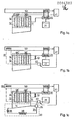
- Fig. 1a - c ein Blockschaltbild der drei aufeinanderfolgenden Betriebsphasen des Sorptionsapparats, und
- Fig. 2 ein Ausführungsbeispiel des Sorp- . tionsapparats mit zwei Kocheradsorbereinheiten.
- 1a-c is a block diagram of the three successive operating phases of the sorption apparatus, and
- Fig. 2 shows an embodiment of the Sorp. tion apparatus with two cooker adsorber units.
In Fig. 1 c ist der Grundaufbau des erfindungsgemäßen Sorptionsapparates dargestellt.1 c shows the basic structure of the sorption apparatus according to the invention.
Ein.an sich bekannter Kocheradsorber 10 enthält in seinem oberen Teil ein Sorptionsmittel 12 und eine Wärmetauschereinrichtung 11. In seinem unteren Teil befindet sich erfindungsgemäß ein Brüdenraum 14, der zugleich Teil der Verdampfereinrichtung 30 ist. Die Verdampfereinrichtung 30 ist hier eine für sich bekannte Bauart eines Umlaufverdampfers mit getrenntem Brüdenraum 14 und Wärmetauscher 38. Erfindungsgemäß erfolgt auch eine Nutzwärmeabgabe an einen Verbraucher 50. Ein Wärmeabgabe-Regler 41 regelt, auf ein Eingriffsorgan 40 wirkend, von den Betriebszuständen des Kocheradsorbers 10'völlig unabhängig, die Wärmeübergabe in einen Kondensator 20. Ein zusätzliches Absperrorgan 13 erlaubt während der Sorptionsphase die Einkopplung von Wärme aus einer Wärmequelle über den Wärmetauscher 38 in den Kocheradsorber 10. Eine weitere Wärmeübergabestelle 60 beim Verbraucher 50 (in Fig. 1c in Strichlinie gezeigt) kann somit entfallen. Zum Betrieb des Sorptionsapparats sind ferner ein Vorratstank 21, eine Nachfülleinrichtung 34 und eine Solepumpe 36 vorgesehen.A
Zur Vereinfachung der Darstellung sind in Fig. 1a - c,von der Desorptionsphase 1a ausgehend, nur die zum Betrieb nötigen bzw. die vorher betriebenen Komponenten dargestellt.To simplify the illustration, only the components required for operation or the components previously operated are shown in FIGS. 1a-c, starting from the desorption phase 1a.
Der Betrieb des Sorptionsapparats setzt sich aus drei Phasen zusammen (F i g . 1).The operation of the sorption apparatus consists of three phases (Fig. 1).
Diese sind:
- 1. Die Desorptions phase ( F i g . 1 a ): Hier wird durch Zufuhr von Desorptionswärme bei hohen Temperaturen das Arbeitsmittel
aus dem Sorptionsmittel 12 ausgetrieben und beiNutzwärmetemperaturen im Kondensator 20 kondensiert. Das kondensierte Arbeitsmittel wird indem Vorratstank 21 gespeichert. Bei Erreichen der Sorptionsmittelendtemperaturwird die Desorptionswärmezufuhr unterbrochen. Die Nutzwärme wird in dieser Phaseüber den Kondensator 20 anden Verbraucher 50 weitergeleitet. - 2.
Die Abküh 1 phase ( F i g . 1 b ) : Über dieWärmetauschereinrichtung 11 wird die gespeicherte spezifische Wärme des Sorptionsmittels 12 anden Verbraucher 50 abgegeben. Dies geschieht entweder über einen Wärmeträgerkreislauf 61 (gestrichelt gezeichnet) oder erfindungsgemäß wiederum überden Kondensator 20. Der Wärmeabgabe-Regler 41 regeltüber das Eingriffsorgan 40 den Verdampfungsdruck des Arbeitsmittels inder Wärmetauschereinrichtung 11.Das Sorptionsmittel 12 kühlt sich dabei ab und reduziert denArbeitsmitteldampfdruck im Kocheradsorber 10 unter den zu Beginn herrschenden Kondensatordruck. - 3. Die Sorptions phase ( F i g . 1 c ): Sobald der
Arbeitsmitteldampfdruck im Kocheradsorber 10 unter den Arbeitsmitteldampfdruck inder Verdampfereinrichtung 30 gesunken ist, kann die Sorptionsphase beginnen.
- 1. The desorption phase (FIG. 1 a): Here, the working medium is expelled from the
sorbent 12 by supplying desorption heat at high temperatures and condensed in thecondenser 20 at useful heat temperatures. The condensed working fluid is stored in thestorage tank 21. When the final sorbent temperature is reached, the desorption heat supply is interrupted. In this phase, the useful heat is passed on to theconsumer 50 via thecondenser 20. - 2. The
cooling 1 phase (FIG. 1 b): the stored specific heat of thesorbent 12 is released to theconsumer 50 via theheat exchanger device 11. This takes place either via a heat transfer circuit 61 (shown in dashed lines) or, according to the invention, again via thecondenser 20. Theheat release controller 41 regulates the evaporation pressure of the working medium in theheat exchanger device 11 via the engagingmember 40. Thesorbent 12 cools down and reduces the working medium vapor pressure in theprocess Kocheradsorber 10 under the condenser pressure prevailing at the beginning. - 3. The sorption phase (Fig. 1 c): As soon as the working fluid vapor pressure in the
stove adsorber 10 has dropped below the working fluid vapor pressure in theevaporator device 30, the sorption phase can begin.
Aus einem Solekreislauf 35 verdampft im Brüdenraum 14 Arbeitsmittel bei tiefen Temperaturen und strömt in das Sorptionsmittel 12, wo es bei höheren Temperaturen sorbiert wird und seine Sorptionswärme freisetzt.Working medium evaporates from a
Die abgekühlte Soleflüssigkeit wird im Wärmetauscher 38 aufgewärmt und erneut in den Brüdenraum 14 geleitet. Das im Brüdenraum 14 verdampfte Arbeitsmittel wird vorher in der Nachfülleinrichtung 34 aus dem Vorratstank 21 aufgefüllt. Die Sorptionswärme wird in dieser Phase auf die gleiche Weise wie in der Abkühlphase zum Verbraucher 50 geleitet.The cooled brine liquid is warmed up in the
_ F i g . 2 zeigt ergänzend zu Fig. 1c die Verschaltung mehrerer Kocheradsorbereinheiten._ F i g. 2 shows, in addition to FIG. 1c, the connection of a plurality of stove adsorber units.
Die Wärmetauschereinrichtungen 11, 11a sind in diesem Beispiel mit einer elektrischen Heizung 17, 17a ausgerüstet. Nur Sorptionsmittelpartien 16, 16a vor den Absperrorganen 13., 13a werden nicht beheizt.In this example, the
Auf der Wärmeabgabeseite ist dem Vorratstank 21 der Kondensator 20 und eine Wasserstrahlpumpe 22 vorgeschaltet. Am unteren Ende des Vorratstanks 21 regelt der Wärmeabgabe-Regler 41 über das Eingriffsorgan 40 den Auslauf zu den Wärmetauschereinrichtungen 11, 11a.The
Eine Arbeitsmittelleitung führt von hier zu der Verdampfereinrichtung 30, welche erfindungsgemäß einen Solekreislauf 35 mit einem absperrbaren Zweig 33, die Nachfülleinrichtung 34 und die Solepümpe 36 enthält. Mit den Brüdenräumen 14, 14a steht dieser Kreislauf über Flüssigkeitsventile 18, 18a und 19, 19a und einem Soleflüssigkeits-Regler 37 in Verbindung. Die beiden Kocheradsorbereinheiten 10 und 10a sind über die beiden Arbeitsmitteldampfleitungen 42 und 44 verbunden.A working medium line leads from here to the
Das Sorptionsmittel 12 wird vorzugsweise während der Niedertarifzeiten durch die elektrische Heizung 17 erhitzt. Der dabei freiwerdende Arbeitsmitteldampf erhöht den Druck im Kocheradsorber 10 bis über den Kondensatordruck. Jetzt kann das Absperrorgan 13 die Dampfleitung zum Kondensator 20 freigeben.The
Im Brüdenraum 14 ist während dieser Desorptionsphase nur Arbeitsmitteldampf, da die Flüssigkeitsventile 18 und 19 den Solekreislauf 35 unterbrechen. Das aus dem Sorptionsmittel 12 ausgetretene und im Kondensator 20 unter Wärmeabgabe an den Wärmeverbraucher 50 kondensierte Arbeitsmittel sammelt sich im Vorratstank 21. Die Wasserstrahlpumpe 22 entfernt erfindungsgemäß aus dem Kondensator 20 die nicht kondensierbaren Gase. ,During this desorption phase there is only working fluid vapor in the
Am Ende der Desorptionsphase schließt das Absperrorgan 13 die Leitung zum Kondensator 20. Der Wärmeabgabe-Regler 41 läßt nun flüssiges Arbeitsmittel aus dem Vorratstank 21, vom Wärmeverbraucher 50 geregelt, in die Wärmetauschereinrichtung 11 einströmen. Das Arbeitsmittel verdampft hier, wobei das Sorptionsmittel 12 von unten nach oben fortschreitend abkühlt. Der Dampfdruck im Kocheradsorber 10 kann jetzt bei geschlossenem Absperrorgan 13 absinken. Sobald dieser Druck unter den Verdampfungsdruck der Soleflüssigkeit gesunken ist, geben die Flüssigkeitsventile 18 und 19 durch den Soleflüssigkeits-Regler 37 geregelt den Solekreislauf 35 durch den Brüdenraum 14 frei. Das Arbeitsmittel verdampft hier und speichert seine Sorptionswärme im Sorptionsmittel 12 auf höherer Temperatur bzw. gibt sie über die Wärmetauschereinrichtung 11 an den Kondensator 20 ab.At the end of the desorption phase, the shut-off
Die Nachfülleinrichtung 34 läßt bei Bedarf aus dem Vorratstank 21 das im Brüdenraum verdampfte Wasser in den Solekreislauf 35 nachströmen.The
Um die Speicherkapazität weiter zu erhöhen, wird das Sorptionsmittel 12 unter die Nutztemperatur abgekühlt, indem der Kondensator 20 von der Wärmetauschereinrichtung 11 abgetrennt und der Arbeitsmitteldampf aus der Wärmetauschereinrichtung 11 über die absperrbare Dampfleitung 42 in den Kocheradsorber 10a geleitet wird. Bedingt durch den höheren Arbeitsmitteldampfdruck kann das Sorptionsmittel 12a im Koäheradsorber 10a weiter sorbieren und die freiwerdende Wärme über die Wärmetauschereinrichtung 11a erfindungsgemäß dem Wärmeverbraucher 50-zuleiten.In order to further increase the storage capacity, the
Besteht während der Sorptionsphase keine Möglichkeit, Wärme aus der Wärmequelle über die Verdampfereinrichtung 30 in das System einzukoppeln, wird dem Kocheradsorber 10 diese Wärmemenge aus der Wärmetauschereinrichtung 11 entnommen, indem ein Teilstrom des Arbeitsmitteldampfes über das Absperrorgan 13 in den Kocheradsorber 10 strömt und vom Sorptionsmittel 12 sorbiert wird.If there is no possibility of coupling heat from the heat source into the system via the
Claims (61)
dadurch gekennzeichnet,
characterized,
dadurch gekennzeichnet,
characterized,
dadurch gekennzeichnet,
characterized,
dadurch gekennzeichnet,
characterized,
dadurch gekennzeichnet,
characterized,
dadurch gekennzeichnet,
characterized,
dadurch gekennzeichnet,
characterized,
dadurch gekennzeichnet,
characterized,
dadurch gekennzeichnet,
characterized,
dadurch gekennzeichnet,
characterized,
dadurch gekennzeichnet,
characterized,
dadurch gekennzeichnet,
characterized,
dadurch gekennzeichnet,
characterized,
Applications Claiming Priority (4)
| Application Number | Priority Date | Filing Date | Title |
|---|---|---|---|
| DE3205285 | 1982-02-15 | ||
| DE3205285 | 1982-02-15 | ||
| DE3207656 | 1982-03-03 | ||
| DE19823207656 DE3207656A1 (en) | 1982-02-15 | 1982-03-03 | SORPTION APPARATUS AND METHOD FOR THEIR OPERATION |
Publications (2)
| Publication Number | Publication Date |
|---|---|
| EP0086383A2 true EP0086383A2 (en) | 1983-08-24 |
| EP0086383A3 EP0086383A3 (en) | 1983-11-16 |
Family
ID=25799601
Family Applications (1)
| Application Number | Title | Priority Date | Filing Date |
|---|---|---|---|
| EP83100852A Withdrawn EP0086383A3 (en) | 1982-02-15 | 1983-01-31 | Sorption apparatuses and method of operating the same |
Country Status (4)
| Country | Link |
|---|---|
| US (1) | US4479364A (en) |
| EP (1) | EP0086383A3 (en) |
| JP (1) | JPH06105140B2 (en) |
| DE (1) | DE3207656A1 (en) |
Cited By (7)
| Publication number | Priority date | Publication date | Assignee | Title |
|---|---|---|---|---|
| EP0158326A2 (en) * | 1984-04-09 | 1985-10-16 | ZEO-TECH Zeolith Technologie GmbH | Adsorption apparatus |
| FR2562994A1 (en) * | 1984-04-13 | 1985-10-18 | Jeumont Schneider | THERMAL ENERGY SENSOR FOR AN ADSORPTION-DESORPTION DEVICE |
| FR2574530A1 (en) * | 1984-12-06 | 1986-06-13 | Jeumont Schneider | THERMAL ENERGY SENSOR AND DEVICE INCLUDING SUCH SENSOR |
| DE3509564A1 (en) * | 1985-03-16 | 1986-09-18 | Thomas Dipl.-Ing. 7500 Karlsruhe Föllinger | Apparatus for carrying out adsorption, desorption and internal heat exchange |
| FR2593588A1 (en) * | 1986-01-28 | 1987-07-31 | Nishiyodo Air Conditioner | REFRIGERATED MACHINE WITH ADSORPTION |
| DE3808653A1 (en) * | 1987-08-28 | 1989-03-09 | Nishiyodo Air Conditioner | ADSORPTION COOLING SYSTEM |
| WO2018033243A1 (en) * | 2016-08-17 | 2018-02-22 | Mahle International Gmbh | Arrangement, particularly refrigerating machine or heat pump |
Families Citing this family (27)
| Publication number | Priority date | Publication date | Assignee | Title |
|---|---|---|---|---|
| DE3336776C2 (en) * | 1983-10-10 | 1986-04-10 | Fritz Dipl.-Ing. Kaubek | Kocheradsorber for sorption apparatus |
| DE3342985A1 (en) * | 1983-11-28 | 1985-06-13 | Fritz Dipl.-Ing. Kaubek | CONTINUOUSLY SORPTION APPARATUS AND METHOD FOR THEIR OPERATION |
| DE3532093C1 (en) * | 1985-09-09 | 1987-04-09 | Schiedel Gmbh & Co | Discontinuous sorption storage device with solid absorber |
| DE3600628A1 (en) * | 1986-01-11 | 1987-07-16 | Degussa | ZEOLITE SHAPED BODY |
| DE3837872A1 (en) * | 1988-11-08 | 1990-05-10 | Zeolith Tech | SORPTION COOLING SYSTEM |
| DE3837880A1 (en) * | 1988-11-08 | 1990-05-10 | Zeolith Tech | REFRIGERATED TANK FOR A SORPTION APPARATUS |
| US5598721A (en) * | 1989-03-08 | 1997-02-04 | Rocky Research | Heating and air conditioning systems incorporating solid-vapor sorption reactors capable of high reaction rates |
| DE4003107A1 (en) * | 1990-02-02 | 1991-08-08 | Zeolith Tech | ICE PRODUCER ACCORDING TO THE SORPTION PRINCIPLE |
| GB9419202D0 (en) * | 1994-09-23 | 1994-11-09 | Univ Warwick | Thermal compressive device |
| DE19522250A1 (en) * | 1995-06-20 | 1997-01-02 | Juergen Dipl Ing Ludwig | Method of operating heat pumps and cooling machines |
| US5823003A (en) * | 1997-05-02 | 1998-10-20 | Uop Llc | Process for heat recovery in a sorption refrigeration system |
| WO1999009365A1 (en) * | 1997-08-13 | 1999-02-25 | Ufe Solar Gmbh | Sorption trap arrangement and method for storing heat |
| DE10015886A1 (en) * | 2000-03-30 | 2001-10-11 | H & P Technologie Gmbh & Co Ge | Reactor for a cooling device |
| DE10250510A1 (en) * | 2002-10-29 | 2004-05-19 | Zeo-Tech Zeolith-Technologie Gmbh | Adsorption cooling device with buffer storage |
| DE10303292A1 (en) * | 2003-01-28 | 2004-07-29 | Zeo-Tech Zeolith-Technologie Gmbh | Mobile cooling container has zeolite absorption system connecting to chamber through back pressure valve with fans in absorption and storage chambers |
| DE10344455A1 (en) * | 2003-09-25 | 2005-05-12 | Zeolith Tech | Process and devices for rapid solidification of hydrous substances |
| WO2006005275A1 (en) * | 2004-07-09 | 2006-01-19 | Fuesting, Bernd | Shaped bodies made of powders or granulated metal, method for the production thereof and their use |
| DE102005034297A1 (en) * | 2005-02-25 | 2006-08-31 | Zeo-Tech Zeolith-Technologie Gmbh | Cooling unit for use in food industry, has sorbent material sealed into sorbent-containing pouch having multilayer sheeting material with metallic layer or metallized layer for allowing vacuo to sorb vaporous working medium |
| FR2886222B1 (en) * | 2005-05-30 | 2008-12-05 | Giat Ind Sa | DEVICE FOR MANAGING THERMAL ENERGY FOR A VEHICLE |
| EP1967799B1 (en) * | 2007-03-05 | 2012-11-21 | ZEO-TECH Zeolith Technologie GmbH | Sorption cooling element with regulating organ and additional heat source |
| EP2006616A2 (en) * | 2007-06-19 | 2008-12-24 | ZEO-TECH Zeolith Technologie GmbH | Flexible sorption cooling element |
| DE102013013835B4 (en) * | 2012-08-22 | 2017-05-18 | Kabushiki Kaisha Toyota Chuo Kenkyusho | Adsorption heat pump system and method for generating cooling power |
| US20140208790A1 (en) * | 2013-01-29 | 2014-07-31 | Baker Hughes Incorporated | Compact dessicant and zeolite bodies for use in a downhole sorption cooling system |
| US10731440B2 (en) | 2013-06-18 | 2020-08-04 | Baker Hughes, A Ge Company, Llc | Downhole fuel cell with steam adsorption and pressure compensation and methods of using same |
| US9593562B2 (en) * | 2013-06-18 | 2017-03-14 | Baker Hughes Incorporated | Downhole fuel cell with steam adsorption and pressure compensation |
| DE102016106234B4 (en) * | 2016-04-06 | 2022-03-03 | Fahrenheit Gmbh | Adsorption heat pump and method for operating an adsorption heat pump |
| RU2763797C1 (en) | 2018-03-02 | 2022-01-11 | Майкл Марк ЭНТОНИ | Methods and devices for humidification and dehumidification for cooling beverages and other food products and production method |
Citations (13)
| Publication number | Priority date | Publication date | Assignee | Title |
|---|---|---|---|---|
| GB388352A (en) * | 1930-05-14 | 1933-02-23 | Wulff Berzelius Normelli | Process for the carrying away of waste heat developed in absorption refrigerators |
| US2182098A (en) * | 1934-09-29 | 1939-12-05 | Mallory & Co Inc P R | Duplex solution thermo-compression process |
| US2293556A (en) * | 1939-04-17 | 1942-08-18 | Honeywell Regulator Co | Adsorption refrigeration system |
| US2353859A (en) * | 1941-04-29 | 1944-07-18 | Servel Inc | Refrigeration |
| FR988886A (en) * | 1944-01-26 | 1951-09-03 | Water heater combined with a refrigerator | |
| US4034569A (en) * | 1974-11-04 | 1977-07-12 | Tchernev Dimiter I | Sorption system for low-grade (solar) heat utilization |
| FR2377589A1 (en) * | 1977-01-17 | 1978-08-11 | Exxon France | HEAT PUMP |
| EP0010551A1 (en) * | 1978-09-13 | 1980-05-14 | GebràDer Sulzer Aktiengesellschaft | Absorption heat pump system |
| US4231772A (en) * | 1978-10-10 | 1980-11-04 | Owens-Illinois, Inc. | Solar powered heat pump construction |
| FR2455713A1 (en) * | 1979-04-30 | 1980-11-28 | Wallsten Hans | DEVICE CONTAINING SORTING BODY AND MANUFACTURING METHOD THEREOF |
| EP0026257A2 (en) * | 1979-09-28 | 1981-04-08 | Georg Dr. Prof. Alefeld | Plant comprising an absorption heat pump |
| US4272268A (en) * | 1977-10-17 | 1981-06-09 | Leonard Greiner | Chemical heat pump |
| GB2088548A (en) * | 1980-11-28 | 1982-06-09 | Exxon Research Engineering Co | Thermal storage heating system |
Family Cites Families (5)
| Publication number | Priority date | Publication date | Assignee | Title |
|---|---|---|---|---|
| US2212869A (en) * | 1938-09-27 | 1940-08-27 | Herbert W Prafcke | Reversible heating and cooling means and method |
| JPS5368447A (en) * | 1976-11-30 | 1978-06-17 | Ebara Corp | Heat-accumulating system |
| US4368624A (en) * | 1980-03-05 | 1983-01-18 | Matsushita Electric Industrial Company, Limited | Absorption type heat pump having indoor and outdoor radiators connected in series in a water flow circuit during heat mode |
| DE3022284A1 (en) * | 1980-06-13 | 1982-01-14 | Alefeld, Georg, Prof.Dr., 8000 München | METHOD AND DEVICE FOR STORING AND HIGH TRANSFORMING THE TEMPERATURE OF HEAT |
| US4337625A (en) * | 1981-03-02 | 1982-07-06 | Battelle Development Corp. | Waste heat driven absorption refrigeration process and system |
-
1982
- 1982-03-03 DE DE19823207656 patent/DE3207656A1/en not_active Withdrawn
-
1983
- 1983-01-31 EP EP83100852A patent/EP0086383A3/en not_active Withdrawn
- 1983-02-15 JP JP58022235A patent/JPH06105140B2/en not_active Expired - Lifetime
- 1983-02-15 US US06/466,575 patent/US4479364A/en not_active Expired - Fee Related
Patent Citations (13)
| Publication number | Priority date | Publication date | Assignee | Title |
|---|---|---|---|---|
| GB388352A (en) * | 1930-05-14 | 1933-02-23 | Wulff Berzelius Normelli | Process for the carrying away of waste heat developed in absorption refrigerators |
| US2182098A (en) * | 1934-09-29 | 1939-12-05 | Mallory & Co Inc P R | Duplex solution thermo-compression process |
| US2293556A (en) * | 1939-04-17 | 1942-08-18 | Honeywell Regulator Co | Adsorption refrigeration system |
| US2353859A (en) * | 1941-04-29 | 1944-07-18 | Servel Inc | Refrigeration |
| FR988886A (en) * | 1944-01-26 | 1951-09-03 | Water heater combined with a refrigerator | |
| US4034569A (en) * | 1974-11-04 | 1977-07-12 | Tchernev Dimiter I | Sorption system for low-grade (solar) heat utilization |
| FR2377589A1 (en) * | 1977-01-17 | 1978-08-11 | Exxon France | HEAT PUMP |
| US4272268A (en) * | 1977-10-17 | 1981-06-09 | Leonard Greiner | Chemical heat pump |
| EP0010551A1 (en) * | 1978-09-13 | 1980-05-14 | GebràDer Sulzer Aktiengesellschaft | Absorption heat pump system |
| US4231772A (en) * | 1978-10-10 | 1980-11-04 | Owens-Illinois, Inc. | Solar powered heat pump construction |
| FR2455713A1 (en) * | 1979-04-30 | 1980-11-28 | Wallsten Hans | DEVICE CONTAINING SORTING BODY AND MANUFACTURING METHOD THEREOF |
| EP0026257A2 (en) * | 1979-09-28 | 1981-04-08 | Georg Dr. Prof. Alefeld | Plant comprising an absorption heat pump |
| GB2088548A (en) * | 1980-11-28 | 1982-06-09 | Exxon Research Engineering Co | Thermal storage heating system |
Cited By (11)
| Publication number | Priority date | Publication date | Assignee | Title |
|---|---|---|---|---|
| EP0158326A2 (en) * | 1984-04-09 | 1985-10-16 | ZEO-TECH Zeolith Technologie GmbH | Adsorption apparatus |
| EP0158326A3 (en) * | 1984-04-09 | 1987-07-15 | Fritz Dipl.-Ing. Kaubek | Adsorption apparatus for use as an electric heat accumulator |
| FR2562994A1 (en) * | 1984-04-13 | 1985-10-18 | Jeumont Schneider | THERMAL ENERGY SENSOR FOR AN ADSORPTION-DESORPTION DEVICE |
| US4697433A (en) * | 1984-04-13 | 1987-10-06 | Jeumont-Schneider Corporation | Thermal energy collector |
| FR2574530A1 (en) * | 1984-12-06 | 1986-06-13 | Jeumont Schneider | THERMAL ENERGY SENSOR AND DEVICE INCLUDING SUCH SENSOR |
| EP0187571A2 (en) * | 1984-12-06 | 1986-07-16 | JEUMONT-SCHNEIDER Société anonyme dite: | Thermal energy collector and device having such a collector |
| EP0187571A3 (en) * | 1984-12-06 | 1986-07-30 | Jeumont-Schneider Societe Anonyme Dite: | Thermal energy collector and device having such a collector |
| DE3509564A1 (en) * | 1985-03-16 | 1986-09-18 | Thomas Dipl.-Ing. 7500 Karlsruhe Föllinger | Apparatus for carrying out adsorption, desorption and internal heat exchange |
| FR2593588A1 (en) * | 1986-01-28 | 1987-07-31 | Nishiyodo Air Conditioner | REFRIGERATED MACHINE WITH ADSORPTION |
| DE3808653A1 (en) * | 1987-08-28 | 1989-03-09 | Nishiyodo Air Conditioner | ADSORPTION COOLING SYSTEM |
| WO2018033243A1 (en) * | 2016-08-17 | 2018-02-22 | Mahle International Gmbh | Arrangement, particularly refrigerating machine or heat pump |
Also Published As
| Publication number | Publication date |
|---|---|
| EP0086383A3 (en) | 1983-11-16 |
| US4479364A (en) | 1984-10-30 |
| JPH06105140B2 (en) | 1994-12-21 |
| JPS58184467A (en) | 1983-10-27 |
| DE3207656A1 (en) | 1983-08-25 |
Similar Documents
| Publication | Publication Date | Title |
|---|---|---|
| EP0086383A2 (en) | Sorption apparatuses and method of operating the same | |
| EP0026257B1 (en) | Plant comprising an absorption heat pump | |
| DE3413349C2 (en) | Method and device for heating with a periodic adsorption storage heat pump | |
| EP2076721B1 (en) | Adsorption heat pump with heat accumulator | |
| DE3532093C1 (en) | Discontinuous sorption storage device with solid absorber | |
| DE69923792T2 (en) | CHEMICAL HEAT PUMP | |
| EP0010551B1 (en) | Absorption heat pump system | |
| CH647590A5 (en) | Process and equipment for producing useful energy from low-grade heat sources | |
| DE2737971A1 (en) | HEAT PUMP WITH A FUEL-FIRED AUXILIARY HEATING DEVICE | |
| AT394200B (en) | METHOD FOR THE USE AND / OR STORAGE OF ENERGY FROM THE ENVIRONMENT | |
| DE2700123A1 (en) | AIR CONDITIONING WITH HEAT PUMP | |
| DE102012009696A1 (en) | Stationary or non stationary system for generating and/or storing of hot or cold water, installed in e.g. house, has heat exchanger that is operated as condenser during desorbent mode, and operated as evaporator during adsorbent mode | |
| EP0091095B1 (en) | Storage heating plant with sorption reservoir | |
| DE2720561C2 (en) | ||
| DD240061A5 (en) | TWIN STORAGE IN THE HEAT TRANSFER CIRCUIT | |
| DE102015208582B4 (en) | Motor vehicle and method for operating a corresponding motor vehicle | |
| DE3129957C2 (en) | ||
| DE626864C (en) | Utilization and storage of waste heat from a continuous absorption refrigeration machine | |
| DE2608873A1 (en) | Heat pump with storage heater for subcooling heat - has two compressors for basic and peak heat requirements | |
| EP0079452A1 (en) | Energy storage unit for the storage of latent heat in chemically reacting storage substances or storage substances with phase change | |
| DE3238333A1 (en) | Heating and cooling device and method | |
| DE102006055280A1 (en) | An adsorption cooling system has two vacuum chambers each housing an adsorption material and heat exchanger and a system of valves directing the flow a water cooling medium | |
| EP0093826A1 (en) | Plant for performing a heat pump process for heating purposes | |
| DE102007039657A1 (en) | Device for heating and air-conditioning of space, particularly vehicle, comprises sorption system which has adsorption or desorption area and evaporator or condenser area, where sorption system is inter-stratified by three fluid flow | |
| DE4440589A1 (en) | Generation of extra cold energy in compressor-driven cooling plant |
Legal Events
| Date | Code | Title | Description |
|---|---|---|---|
| PUAI | Public reference made under article 153(3) epc to a published international application that has entered the european phase |
Free format text: ORIGINAL CODE: 0009012 |
|
| PUAI | Public reference made under article 153(3) epc to a published international application that has entered the european phase |
Free format text: ORIGINAL CODE: 0009012 |
|
| AK | Designated contracting states |
Designated state(s): AT CH DE FR GB IT LI SE |
|
| PUAL | Search report despatched |
Free format text: ORIGINAL CODE: 0009013 |
|
| AK | Designated contracting states |
Designated state(s): AT CH DE FR GB IT LI SE |
|
| 17P | Request for examination filed |
Effective date: 19840514 |
|
| RAP1 | Party data changed (applicant data changed or rights of an application transferred) |
Owner name: HIERONIMI, ULRICH-M. |
|
| 18D | Application deemed to be withdrawn |
Effective date: 19880411 |
|
| STAA | Information on the status of an ep patent application or granted ep patent |
Free format text: STATUS: THE APPLICATION IS DEEMED TO BE WITHDRAWN |
|
| R18D | Application deemed to be withdrawn (corrected) |
Effective date: 19880408 |
|
| RIN1 | Information on inventor provided before grant (corrected) |
Inventor name: MAIER-LAXHUBER, PETER |