EP0084680A1 - Appareil pour lier des balles dans une presse à balles - Google Patents
Appareil pour lier des balles dans une presse à balles Download PDFInfo
- Publication number
- EP0084680A1 EP0084680A1 EP82112057A EP82112057A EP0084680A1 EP 0084680 A1 EP0084680 A1 EP 0084680A1 EP 82112057 A EP82112057 A EP 82112057A EP 82112057 A EP82112057 A EP 82112057A EP 0084680 A1 EP0084680 A1 EP 0084680A1
- Authority
- EP
- European Patent Office
- Prior art keywords
- catch
- wire
- finger
- wires
- catching
- Prior art date
- Legal status (The legal status is an assumption and is not a legal conclusion. Google has not performed a legal analysis and makes no representation as to the accuracy of the status listed.)
- Granted
Links
- 238000005520 cutting process Methods 0.000 claims abstract description 28
- 238000005553 drilling Methods 0.000 claims abstract description 23
- 238000005452 bending Methods 0.000 claims description 7
- 238000006073 displacement reaction Methods 0.000 claims description 5
- 238000003825 pressing Methods 0.000 abstract description 5
- 238000000034 method Methods 0.000 description 12
- 208000027418 Wounds and injury Diseases 0.000 description 6
- 230000006378 damage Effects 0.000 description 6
- 208000014674 injury Diseases 0.000 description 6
- 238000003860 storage Methods 0.000 description 4
- 241001295925 Gegenes Species 0.000 description 2
- 238000004519 manufacturing process Methods 0.000 description 2
- 240000003517 Elaeocarpus dentatus Species 0.000 description 1
- 230000001154 acute effect Effects 0.000 description 1
- 230000015572 biosynthetic process Effects 0.000 description 1
- 230000000981 bystander Effects 0.000 description 1
- 238000010276 construction Methods 0.000 description 1
- 238000007598 dipping method Methods 0.000 description 1
- 230000007704 transition Effects 0.000 description 1
Images


Classifications
-
- A—HUMAN NECESSITIES
- A01—AGRICULTURE; FORESTRY; ANIMAL HUSBANDRY; HUNTING; TRAPPING; FISHING
- A01F—PROCESSING OF HARVESTED PRODUCE; HAY OR STRAW PRESSES; DEVICES FOR STORING AGRICULTURAL OR HORTICULTURAL PRODUCE
- A01F15/00—Baling presses for straw, hay or the like
- A01F15/08—Details
- A01F15/14—Tying devices specially adapted for baling presses
- A01F15/146—Wire twisters
-
- B—PERFORMING OPERATIONS; TRANSPORTING
- B30—PRESSES
- B30B—PRESSES IN GENERAL
- B30B9/00—Presses specially adapted for particular purposes
- B30B9/30—Presses specially adapted for particular purposes for baling; Compression boxes therefor
- B30B9/3003—Details
Definitions
- the invention relates to a device for strapping bales, which are produced in the baling channel of a baler by means of a press ram and pressed into at least one wire loop fed by two wire storage reels, a storage reel providing an upper wire which runs over two deflection rollers mounted on both sides of a tying head while the another supply roll delivers a lower wire, which is and remains connected to the upper wire, with a lacing needle, the path of which penetrates the press channel and pulls the lower wire behind the finished bale as a wire loop, the tying head being a drilling tool for producing two successive drill points from the upper wire and the adjacent wire of the wire loop and a cutting device for cutting the wires between the two drill points.
- the bale is held together by several parallel wire loops; in the following description, however, for the sake of clarity, only one wrap level is used.
- a device of the type described above is described in DE-OS 24 19 151. It has a wire spool above and below the press channel. The ends of the wires coming from the bobbins are twisted together from the previous work cycle, the lower wire running from its supply spool around the front of the bale being formed to the connection point, and initially by a deflection roller arranged near the bale edge facing the press ram, just above the bale Press channel is led. After pulling up the lower wire in an open loop, the drilling and separating device (in the further drilling device) moves into the working position and first takes the top wire and then the closest section of the open loop into the twisting wheel, whereupon the twisting and subsequent cutting takes place.
- the invention is therefore based on the object to provide a device with which bales can be strapped in such a way that the twist that concludes the strapping no longer protrudes beyond the rear edge of the bale seen in the pressing direction.
- this is achieved in a device of the type mentioned above in that the distance between the lower deflection roller and the press end position of the press die is at least equal to the distance between the lower deflection roller and the separating device and at least one catch finger transversely on the from the lacing needle and between the Deflection wires to keep wires taut Bringing together the wires to be twisted together in the drilling tool.
- the twist terminating the tying point is produced at least at a distance corresponding to its length from the upper edge of the rear face of the bale, so that it cannot protrude beyond the latter even in a state bent towards the rear face of the bale.
- the risk of injury to bystanders from the sharp-edged drill points is completely eliminated when the bale is manipulated using a forklift or crane.
- the catch finger can be designed as a lever which can be pivoted for example on the same axis of rotation as the upper deflection roller for the top wire and can be connected to a pivot drive.
- the free end of the lever is advantageously fork-shaped and is provided on the outside with a run-on slope for guiding the wire section to be caught.
- the tip of the catching finger is designed in the manner of a barb, and the catching finger carries out a simple reciprocating movement to bring the nearest part of the open wire loop closer.
- the advantage is achieved that the drilling point then created when this bale is moved further, namely while pressing a new bale under this deflection roller in contact with it is pushed through, which leads to the fact that this drilling point is then bent towards the bale surface or even pressed into it, which means an additional advantage in terms of avoiding the risk of injury and getting caught with other bales.
- the object on which the invention is based can advantageously be achieved in a further embodiment on the basis of the inventive idea to be derived from the main claim by assigning two catch fingers as catch fingers with a drill tool function to each drill point; the catch fingers preferably cooperate with clamping jaws, so that here an assembly is created which contains the catch fingers which fulfill several functions as a special element.
- the preferred configuration of these catch fingers and thus overall of the lacing head designed as a compact unit in this embodiment can be seen from the further subclaims.
- the aforementioned jaws which interact with the catch fingers, in particular in direct association with the specially designed, hook-shaped catch finger ends, advantageously lead to the wire ends being bent over, which not only increases the strength of the twist point, but also the advantage in the majority of cases sets the sharp ends to face the bale surface, ie additional precautions have been taken even without dipping into the bale surface, at least with regard to the risk of injury.
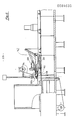
- a press ram 2 with frontal lacing grooves 3 can be moved back and forth by means of a drive (not shown).
- a feed chute la for the material to be pressed in the range of motion of the press ram 2, 3.
- the production of a bale 4 requires several working strokes of the press ram until the bale 4 can be strapped. In the situation shown in FIG. 1, the bale 4 has reached its final dimension and is ready to be tied up, a bale 5 has already been tied up.
- the press ram 2, 3 remains in its front end position (represented by arrowhead 36) and holds the filling of the pressed bale 4 together until the strapping process has ended.
- the head of the press ram 2 has the above-mentioned lacing grooves 3, which run in a path or movement axis 6a of a lacing needle 6, which ent speaking slots in the press box walls are assigned.
- the lacing needle 6 lowers through these slits and the lacing grooves 3 in the head of the ram 2 to below the press box, takes a bottom wire 8 coming from a lower supply spool 7 and running to the (in the direction of conveyance) front lower edge of the bale 4 and forms the next one Raising an open loop 8a, 8b between a deflection roller 11, the head 6b of the lacing needle 6 and the lower rear edge of the bale 4.
- a lacing head 12 now moves forward into a working position in a frame 13, guided in a path 13a, whereby a Insert wire section 15 of an upper wire 14 between deflection rollers 16 and 17 into the twist slot of a twist wheel 12a of the lacing head 12 to such an extent that it reaches the bottom of the twist slot.
- a catch finger 18 designed as a lever is now pivoted back with the aid of a drive 19 in the direction of the movement axis 6a of the lace 6 until its catch notch 18a (FIGS. 2-4) behind the section 8b of the open wire loop 8a, 8b closest to the wire section 15 has reached (see dash-dotted representation in Fig. 1). It moves parallel to the plane defined by the wire loop 8a, 8b at a distance from it, which just prevents contact between the catching finger 18 and the wire sections 8a and 8b.
- the head of the catch finger 18 with the catch notch 18a is offset so far into the loop plane with respect to the catch finger itself that the latter passes exactly through the catch notch 18a.
- the catch notch 18a is fork-shaped and a roller 18b is inserted between the two legs in the base of the notch such that the groove of the roller 18b takes over the wire guidance.
- a further possibility for catching the section 8b of the loop 8a, 8b results from a brief lateral displacement of the catching finger 18 while the finger head is moving past the wire section 8b.
- the twisting wheel 12a After inserting the two wires 8 and 14 or their sections 8b and 15, the twisting wheel 12a is set in motion, as a result of which the two wire sections 8b and 15 are twisted in two sections above and below the twisting slot in opposite directions to twisting points 9 and 10 . Then the wire connection is cut approximately in the middle between the two drill points by means of a cutting device 23, and then the lacing needle 6 is lowered somewhat.
- the device according to the invention also has the option of bending the two drill points 9, 10 for each after cutting, with the aid of two bending devices 21 and 22, the first of which consists of a fixed abutment 21a and an associated movable counter edge 21b, while the second lower bending device 22 has a fixed abutment 22a, as the movable opposite edge of which acts the notch 18a of the catching finger 18.
- the opposite edge 21b is also attached to the catching finger 18, which is briefly pivoted counterclockwise by a sufficient amount from the rest position in order to carry out the turning process after the cutting process. Then catch finger 18 and lace 12 return to their starting positions.
- the press ram 2 When the press ram 2 is retrieved for receiving the first batch of material for the next bale 4, the now tied bale 4 expands somewhat, as a result of which the tying is stretched, which leads to the lower drilling point 10 laying firmly on the top of the bale.
- the finished bale 4 is pushed further during the pressing of a new bale, the drilling point 10 then being passed under the deflection roller 16. This results in the additional possibility of pressing the drilling point with its sharp end into the bale surface by means of a suitable guide, if desired.
- the upper drill point 9 tightens as the new bale following the bale 4 grows and finally, after passing through the roll 16, likewise lies on the bale surface.
- the next strapping process begins as soon as the new bale has reached its intended size.
- the entire assembly 24 comprising the lacing head with drives and carrying device is shown schematically.
- the frame 13 serves as a supporting frame and is rigidly connected to the press frame in a manner not shown.
- Part of the frame 13 is a laterally open U-profile as Guideway for the lacing head 12.
- the assembly 24 consists of the pivotable fastening in a bearing 25 coaxial to the upper deflection roller 17 on a crossmember 26 of the frame 13, catch fingers 18 designed as levers, the rollers 16 and 17 delimiting the drilling section, the bending devices 21 and 22, the cutting device 23, a hydraulic cylinder 27 as a drive for the lacing head 12 and a hydraulic cylinder 19 as a swivel drive for the catch finger 18.
- the cord head 12 is guided with the aid of rollers 28 in the guide track 13a. Its path is dimensioned such that the upper wire 14 is safely released from the lacing head in its rest position, while the working position is adjusted such that the wire section 15 touches the bottom of the slot in the twisting wheel 12a.
- the hydraulic cylinder 27 is supported via an abutment 29 on the guide track 13a belonging to the frame 13; its piston rod is connected with its head 30 to a nose 31 fastened to the lace head 12, via which it moves the lace head 12.
- the swivel drive 19 for the catch finger 18 is finally supported at 32 on the frame 13.
- the directional arrows 33, 34 and 35 shown in FIG. 2 indicate the running direction of the wires 8 and 14 during the operation of the baler.
- FIGS. 5 to 10 A second exemplary embodiment of the invention is described below with reference to FIGS. 5 to 10, the baler shown essentially corresponding to that according to FIG. 1, that is to say here also a press box 101 with a rectangular cross section, a press die 102 with frontal lacing grooves 103, and a filling chute 101a Lace 106 at least one lower supply spool 107 is provided for the lower wire 108 with a deflection roller 111.
- the work flow is also essentially the same and will be described again in detail below for the second exemplary embodiment with reference to FIGS. 5 to 7.
- the structure of the second embodiment of the tying head is explained with reference to FIGS. 8 to 10:
- FIG. 8 shows a top view of a tying device with a tying head 112 with four pairs of catch hooks 125, which is therefore suitable for the simultaneous production of four parallel wire loops.
- a traverse 137 four yokes 124 are fixed at equal intervals so that they can be moved together using a clamping and cutting cylinder 128.
- the crossmember 137 together with the transverse web 138 and longitudinal webs 139, forms a first frame 113 which can be moved independently of a second frame consisting of a drive box 132 serving as a crossbar, a rear crossbar 134 and two longitudinal webs 140.
- the clamping and cutting cylinder acting on the crossbar 138 128 is supported against a sheet 141 connected to the cross member 134.
- the second frame 142 consisting of the drive box 132, the rear crossmember 134 and the two longitudinal webs 140, can be moved on rollers 133 in the running rails 113a, which are arranged at an acute angle to the horizontal, and is moved by means of a displacement drive 119.
- the drive box 132 has a bearing for the rear ends of the catching fingers 118, which is arranged coaxially to guide bores 135 in the yokes for each catching finger 118.
- the drill drive 129 common to the four tying heads on its rear attached, which is connected in a conventional manner with the individual catch fingers, for. B.
- the yoke 124 consists of a front part with the clamping jaws 121 and 122 fixed thereon and the cutting blade 123a, which is attached to the counter blade 123b fastened to only one of the two catch hooks 125 of a tying head 112 interacts when cutting wires 108b and 115, and a rear part, which has the actual storage for the longitudinal and rotary movement; In the embodiment shown, this extends to the front yoke part and is carried out in a conventional manner, which is why details of the bearing design have been omitted.
- Each catch finger 118 consists of a cylindrical part running in the guide bores 135 and a catch hook 125 forming the head with a run-on bevel 120 and a wire guide roller 126.
- One of the catch hooks 125 of a fastening head 112 carries the counter-blade 123b which rotates during the drilling process.
- the figure shows the catch hook 118 in the clamping and cutting position and clearly shows the function of the separating device and the clamping jaws.
- FIG. 10 shows a catch hook 125 in a position perpendicular to the wire loop plane after the two wires 108b and 115 have been caught. It shows how the two wires are inserted into a hook mouth 127 and guided on a roller 126, which is preferably provided, and by means of the clamping jaw 121 are held.
- the lacing head 112 on the second frame 142 driven by the displacement drive 119, is moved forward along the path 113a into the catch position, but the yoke 124 is clearly in front of the wire section 115 when viewed in the direction of movement of the top wire 114 is held.
- the catch hooks 125 of the catch fingers 118 are moved further in the direction of the guide track 106a of the cord needle 106 until the openings of the hook jaws 127 behind the closest section 108b of the open wire loop 108a, 108b have arrived; they move in or parallel to the plane defined by the wire loop 108a, 108b.
- the catch hooks 125 of the catch fingers 118 lie with their hook jaws 127 in the loop plane.
- the lateral pushing away of the wires 108b and 115 when the catch hooks are extended in the catch position is facilitated by a run-on slope 120 on the front of each catch hook 125.
- the wires 108b and 115 pushed to the side jump into the hook mouths and lie in the hook base on the wire guide roller 126.
- the tying head 112 After the wire section 108b of the open wire loop 108a, 108b has jumped into the hook mouths 127 of the two catching fingers 118 arranged parallel to one another in the wire loop plane, the tying head 112 is moved back into its basic position. Here, the wire 115 pushed to the side also jumps into the hook jaws, so that both wire sections 108b and 115 now lie at the bottom of both hook jaws 127.
- the clamping and cutting drive in the illustrated case a hydraulic cylinder 128 (FIG. 8) , effective.
- the cutting device 123a, 123b cuts through the two wires 108b and 115 and practically at the same time the two clamping jaws 121 and 122 rest on the wires 108b and 115 lying around the guide rollers 126 and press them against the guide rollers 126 so that they are securely held.
- the drill drive 129 is then started, whereby the two drill points 109 and 110 are generated synchronously, but separately. By releasing the clamping and cutting drive 128, the two drill points 109 and 110 are then released.
- the catching, cutting and clamping process can also be carried out with only one drive, for example the catching finger drive 119.
- the severing and clamping can take place when the basic position is reached, after which the drill drive is then actuated. It only has to be ensured that the two drilling points are released after the drilling process.
Applications Claiming Priority (4)
| Application Number | Priority Date | Filing Date | Title |
|---|---|---|---|
| DE3202183 | 1982-01-25 | ||
| DE3202183 | 1982-01-25 | ||
| DE19823247147 DE3247147A1 (de) | 1982-01-25 | 1982-12-21 | Vorrichtung zum umschnueren von ballen in einer ballenpresse |
| DE3247147 | 1982-12-21 |
Publications (2)
| Publication Number | Publication Date |
|---|---|
| EP0084680A1 true EP0084680A1 (fr) | 1983-08-03 |
| EP0084680B1 EP0084680B1 (fr) | 1986-03-19 |
Family
ID=25799056
Family Applications (1)
| Application Number | Title | Priority Date | Filing Date |
|---|---|---|---|
| EP82112057A Expired EP0084680B1 (fr) | 1982-01-25 | 1982-12-28 | Appareil pour lier des balles dans une presse à balles |
Country Status (6)
| Country | Link |
|---|---|
| US (1) | US4459904A (fr) |
| EP (1) | EP0084680B1 (fr) |
| BR (1) | BR8300339A (fr) |
| DE (2) | DE3247147A1 (fr) |
| ES (1) | ES519223A0 (fr) |
| SU (1) | SU1246885A3 (fr) |
Cited By (4)
| Publication number | Priority date | Publication date | Assignee | Title |
|---|---|---|---|---|
| FR2579862A1 (fr) * | 1985-04-03 | 1986-10-10 | Rivierre Casalis | |
| EP0235378A2 (fr) * | 1986-02-27 | 1987-09-09 | Paal's Packpressen-Fabrik GmbH & Co. KG | Machine pour presser et lier des balles |
| EP0464651A1 (fr) * | 1990-06-27 | 1992-01-08 | GREENLAND GMBH & CO. KG | Presse pour grandes balles |
| EP2926646A1 (fr) * | 2014-03-31 | 2015-10-07 | CNH Industrial Belgium nv | Ensemble de nouage pour machine agricole |
Families Citing this family (19)
| Publication number | Priority date | Publication date | Assignee | Title |
|---|---|---|---|---|
| DE3346051A1 (de) * | 1983-12-20 | 1985-07-25 | Hermann 7777 Salem Schwelling | Verfahren und vorrichtung zum selbsttaetig maschinellen umreifen und abbinden hochverdichteter ballen aus abfallmaterialien, mittels eines oder mehrerer bindedraehte |
| US4805528A (en) * | 1984-09-18 | 1989-02-21 | Rogers Thomas A | Cotton bale recompressing and retying machine and process |
| US4718336A (en) * | 1986-10-22 | 1988-01-12 | Cives Corp. | Modular automatic bale tier |
| FR2650989B1 (fr) * | 1989-08-21 | 1991-11-29 | Botalam Sarl | Dispositif de liage a tete de torsadage perfectionnee et lieuse equipee de tels dispositifs, notamment pour le liage de couronnes de fil de fer |
| US6283017B1 (en) | 1995-10-24 | 2001-09-04 | L & P Property Management Company | Apparatus for tying and binding bales of compressed materials |
| US5704283A (en) * | 1995-10-24 | 1998-01-06 | L & P Property Management Company | Automatic tie system for baler |
| US5921289A (en) * | 1997-06-10 | 1999-07-13 | L&P Property Management Company | Method and apparatus for tying and binding bales of compressed materials |
| DE19808416C2 (de) * | 1998-02-28 | 1999-12-23 | Hermann Schwelling | Antriebs- und Lagerungsvorrichtung für die Verdrillscheiben der Umschnüreinrichtung für Abfälle von Ballenpressen |
| US6173932B1 (en) | 1998-06-04 | 2001-01-16 | L&P Property Management Company | Mounting device for mounting a hand tying device to a bale of compressed material |
| US6009646A (en) * | 1998-06-05 | 2000-01-04 | L&P Property Management Company | Apparatus for tying and binding bales of compressed materials |
| US6032575A (en) * | 1998-07-16 | 2000-03-07 | L&P Property Management Company | Automatic baler with tying system having simultaneously engaged twister pinions |
| US6363843B1 (en) | 1999-09-02 | 2002-04-02 | L&P Property Management Company | Wire tie guide with tying device and method |
| US7389724B2 (en) * | 2004-12-17 | 2008-06-24 | Marathon Equipment Company | Waste baling method and apparatus |
| US7690402B2 (en) * | 2005-09-11 | 2010-04-06 | Machinefabriek Bollegraaf Appingedam B.V. | Method, an implement and a twister for tying together end portions of wire material extending around a bale |
| EP2921413A4 (fr) * | 2012-11-16 | 2016-07-27 | Hojaoli Energy S L | Machine à ficeler les ballots à haute précision et procédé de ficelage |
| WO2014144566A1 (fr) * | 2013-03-15 | 2014-09-18 | Cnh Industrial America Llc | Système de cerclage pour instrument agricole |
| BR112015023656B1 (pt) * | 2013-03-15 | 2020-07-28 | Cnh Industrial America Llc | sistema de cintagem para implemento agrícola |
| BR112015023598B1 (pt) * | 2013-03-15 | 2020-07-14 | Cnh Industrial America Llc | Método para cintar um material em um implemento agrícola usando um sistema de cintagem |
| PL2941951T3 (pl) * | 2014-05-05 | 2018-09-28 | Bollegraaf Patents And Brands B.V. | Belująca prasa z układem wiązania sznura i sposób dostarczania sznura do wiązarki węzłów belującej prasy |
Citations (3)
| Publication number | Priority date | Publication date | Assignee | Title |
|---|---|---|---|---|
| US2742062A (en) * | 1944-06-19 | 1956-04-17 | Oliver Corp | Tying mechanism for balers |
| US2757600A (en) * | 1953-03-31 | 1956-08-07 | Sperry Rand Corp | Barrel knot tying mechanism for automatic balers |
| FR2394977A1 (fr) * | 1977-06-21 | 1979-01-19 | Borg & Mensinga Maschf | Procede et appareil de ficelage de balles |
Family Cites Families (6)
| Publication number | Priority date | Publication date | Assignee | Title |
|---|---|---|---|---|
| GB834804A (en) * | 1955-04-26 | 1960-05-11 | Massey Ferguson Inc | Improvements in and relating to balers |
| DE2111894C3 (de) * | 1971-03-12 | 1980-07-10 | Persoener Ab, Ystad (Schweden) | Vorrichtung zum Umbinden von Ballen mit einem PreBkanal und einem im Preßkanal hin- und herverschiebbaren Preßkolben |
| DE2419151A1 (de) * | 1974-04-20 | 1975-11-06 | Lindemann Maschfab Gmbh | Vorrichtung zum umschnueren von ballen |
| DE2460464C3 (de) * | 1974-12-20 | 1981-11-26 | Lindemann Maschinenfabrik GmbH, 4000 Düsseldorf | Umschnürungsvorrichtung an einer Ballenpresse |
| DE2713412C2 (de) * | 1977-03-26 | 1983-02-24 | Lindemann Maschinenfabrik GmbH, 4000 Düsseldorf | Vorrichtung zum Verschnüren von Ballen in einer Ballenpresse |
| FR2441485A1 (fr) * | 1978-11-15 | 1980-06-13 | Mach Applic Environnement | Presse pour la confection de balles de matieres en vrac avec dispositif pour le cerclage des balles au moyen de fils de metal |
-
1982
- 1982-12-21 DE DE19823247147 patent/DE3247147A1/de not_active Withdrawn
- 1982-12-28 DE DE8282112057T patent/DE3270049D1/de not_active Expired
- 1982-12-28 EP EP82112057A patent/EP0084680B1/fr not_active Expired
-
1983
- 1983-01-24 BR BR8300339A patent/BR8300339A/pt not_active IP Right Cessation
- 1983-01-24 ES ES519223A patent/ES519223A0/es active Granted
- 1983-01-24 US US06/460,362 patent/US4459904A/en not_active Expired - Fee Related
- 1983-01-25 SU SU833549999A patent/SU1246885A3/ru active
Patent Citations (3)
| Publication number | Priority date | Publication date | Assignee | Title |
|---|---|---|---|---|
| US2742062A (en) * | 1944-06-19 | 1956-04-17 | Oliver Corp | Tying mechanism for balers |
| US2757600A (en) * | 1953-03-31 | 1956-08-07 | Sperry Rand Corp | Barrel knot tying mechanism for automatic balers |
| FR2394977A1 (fr) * | 1977-06-21 | 1979-01-19 | Borg & Mensinga Maschf | Procede et appareil de ficelage de balles |
Cited By (6)
| Publication number | Priority date | Publication date | Assignee | Title |
|---|---|---|---|---|
| FR2579862A1 (fr) * | 1985-04-03 | 1986-10-10 | Rivierre Casalis | |
| EP0199615A1 (fr) * | 1985-04-03 | 1986-10-29 | Rivierre Casalis | Presse à balles parallélépipédiques avec dispositif de réduction et de compensation de la tension du fil de liage |
| EP0235378A2 (fr) * | 1986-02-27 | 1987-09-09 | Paal's Packpressen-Fabrik GmbH & Co. KG | Machine pour presser et lier des balles |
| EP0235378A3 (en) * | 1986-02-27 | 1989-02-22 | Paal's Packpressen-Fabrik Gmbh & Co. Kg | Machine for pressing and tying bales machine for pressing and tying bales |
| EP0464651A1 (fr) * | 1990-06-27 | 1992-01-08 | GREENLAND GMBH & CO. KG | Presse pour grandes balles |
| EP2926646A1 (fr) * | 2014-03-31 | 2015-10-07 | CNH Industrial Belgium nv | Ensemble de nouage pour machine agricole |
Also Published As
| Publication number | Publication date |
|---|---|
| ES8400321A1 (es) | 1983-10-16 |
| BR8300339A (pt) | 1983-10-25 |
| SU1246885A3 (ru) | 1986-07-23 |
| EP0084680B1 (fr) | 1986-03-19 |
| ES519223A0 (es) | 1983-10-16 |
| DE3247147A1 (de) | 1983-07-28 |
| US4459904A (en) | 1984-07-17 |
| DE3270049D1 (en) | 1986-04-24 |
Similar Documents
| Publication | Publication Date | Title |
|---|---|---|
| EP0084680B1 (fr) | Appareil pour lier des balles dans une presse à balles | |
| DE2713412C2 (de) | Vorrichtung zum Verschnüren von Ballen in einer Ballenpresse | |
| DE2709248C2 (de) | Verfahren und Vorrichtung zum Umschnüren von Ballen | |
| DE2419151A1 (de) | Vorrichtung zum umschnueren von ballen | |
| EP0084620B1 (fr) | Appareil pour cercler des balles | |
| DE1937950A1 (de) | Ballenbindemaschine | |
| DE2656457B2 (de) | Ballenpresse | |
| DE2460464C3 (de) | Umschnürungsvorrichtung an einer Ballenpresse | |
| DE102012008554A1 (de) | Kanalballenpresse | |
| DE2628540B2 (de) | Vorrichtung zum Umschnüren von Ballen | |
| DE3139175C2 (de) | Vorrichtung zum Umschnüren von Ballen | |
| EP4091808B1 (fr) | Procédé de changement de cerclage, ainsi que presse à balles destinée à l'utilisation du procédé | |
| EP0466024B1 (fr) | Presse à balles pour la production de balles ligaturées de déchets hautement compactés | |
| DE3544773C2 (fr) | ||
| EP2478757B1 (fr) | Presse à empaqueter | |
| EP2660160A2 (fr) | Presse à paquet à canal | |
| DE2253160A1 (de) | Verfahren zum anbringen eines bindedrahtes an einem gepressten ballen sowie vorrichtung zur ausfuehrung des verfahrens | |
| DE3822553A1 (de) | Verfahren und vorrichtung zum umschnueren von rundballen aus landwirtschaftlichem erntegut | |
| DE2552722C3 (de) | Kanalpresse mit einem mit Schermessern und Schnürnuten versehenen Preßstempel | |
| DE2833257A1 (de) | Verfahren zum ballenpressen und ballenpresse fuer heu, stroh u.dgl. | |
| DE3406515C2 (fr) | ||
| EP0400380A1 (fr) | Appareil pour cercler des balles faites dans une presse à balles | |
| AT406454B (de) | Vorrichtung zum abbinden von mehreren, im wesentlichen übereinanderliegenden gegenständen | |
| DE102008010155A1 (de) | Verfahren und Vorrichtung zum Abbinden eines Ballens | |
| DE102022108056A1 (de) | Kanalballenpresse mit Kreuzabbindung |
Legal Events
| Date | Code | Title | Description |
|---|---|---|---|
| PUAI | Public reference made under article 153(3) epc to a published international application that has entered the european phase |
Free format text: ORIGINAL CODE: 0009012 |
|
| AK | Designated contracting states |
Designated state(s): DE FR GB IT NL SE |
|
| 17P | Request for examination filed |
Effective date: 19840117 |
|
| GRAA | (expected) grant |
Free format text: ORIGINAL CODE: 0009210 |
|
| ITF | It: translation for a ep patent filed |
Owner name: BARZANO' E ZANARDO ROMA S.P.A. |
|
| AK | Designated contracting states |
Kind code of ref document: B1 Designated state(s): DE FR GB IT NL SE |
|
| REF | Corresponds to: |
Ref document number: 3270049 Country of ref document: DE Date of ref document: 19860424 |
|
| ET | Fr: translation filed | ||
| PLBE | No opposition filed within time limit |
Free format text: ORIGINAL CODE: 0009261 |
|
| STAA | Information on the status of an ep patent application or granted ep patent |
Free format text: STATUS: NO OPPOSITION FILED WITHIN TIME LIMIT |
|
| 26N | No opposition filed | ||
| ITTA | It: last paid annual fee | ||
| PGFP | Annual fee paid to national office [announced via postgrant information from national office to epo] |
Ref country code: SE Payment date: 19911113 Year of fee payment: 10 |
|
| PGFP | Annual fee paid to national office [announced via postgrant information from national office to epo] |
Ref country code: FR Payment date: 19911211 Year of fee payment: 10 |
|
| PGFP | Annual fee paid to national office [announced via postgrant information from national office to epo] |
Ref country code: GB Payment date: 19911212 Year of fee payment: 10 |
|
| PGFP | Annual fee paid to national office [announced via postgrant information from national office to epo] |
Ref country code: NL Payment date: 19911231 Year of fee payment: 10 |
|
| PGFP | Annual fee paid to national office [announced via postgrant information from national office to epo] |
Ref country code: DE Payment date: 19920224 Year of fee payment: 10 |
|
| PG25 | Lapsed in a contracting state [announced via postgrant information from national office to epo] |
Ref country code: GB Effective date: 19921228 |
|
| PG25 | Lapsed in a contracting state [announced via postgrant information from national office to epo] |
Ref country code: SE Effective date: 19921229 |
|
| PG25 | Lapsed in a contracting state [announced via postgrant information from national office to epo] |
Ref country code: NL Effective date: 19930701 |
|
| NLV4 | Nl: lapsed or anulled due to non-payment of the annual fee | ||
| GBPC | Gb: european patent ceased through non-payment of renewal fee |
Effective date: 19921228 |
|
| PG25 | Lapsed in a contracting state [announced via postgrant information from national office to epo] |
Ref country code: FR Effective date: 19930831 |
|
| PG25 | Lapsed in a contracting state [announced via postgrant information from national office to epo] |
Ref country code: DE Effective date: 19930901 |
|
| REG | Reference to a national code |
Ref country code: FR Ref legal event code: ST |
|
| EUG | Se: european patent has lapsed |
Ref document number: 82112057.3 Effective date: 19930709 |