EP2478757B1 - Presse à empaqueter - Google Patents
Presse à empaqueter Download PDFInfo
- Publication number
- EP2478757B1 EP2478757B1 EP12158101.1A EP12158101A EP2478757B1 EP 2478757 B1 EP2478757 B1 EP 2478757B1 EP 12158101 A EP12158101 A EP 12158101A EP 2478757 B1 EP2478757 B1 EP 2478757B1
- Authority
- EP
- European Patent Office
- Prior art keywords
- press
- baler
- channel
- pull
- head pieces
- Prior art date
- Legal status (The legal status is an assumption and is not a legal conclusion. Google has not performed a legal analysis and makes no representation as to the accuracy of the status listed.)
- Active
Links
- 238000003825 pressing Methods 0.000 claims description 37
- 239000000463 material Substances 0.000 claims description 33
- 230000007704 transition Effects 0.000 claims description 10
- 238000005520 cutting process Methods 0.000 claims description 4
- 230000000284 resting effect Effects 0.000 claims 1
- 239000004033 plastic Substances 0.000 description 18
- 239000002699 waste material Substances 0.000 description 15
- 238000000034 method Methods 0.000 description 4
- 238000003860 storage Methods 0.000 description 4
- 230000015572 biosynthetic process Effects 0.000 description 3
- 238000004519 manufacturing process Methods 0.000 description 3
- 239000000919 ceramic Substances 0.000 description 2
- 238000007654 immersion Methods 0.000 description 2
- 238000012423 maintenance Methods 0.000 description 2
- 239000000203 mixture Substances 0.000 description 2
- 239000000123 paper Substances 0.000 description 2
- 230000001681 protective effect Effects 0.000 description 2
- 230000005236 sound signal Effects 0.000 description 2
- 241001295925 Gegenes Species 0.000 description 1
- 244000007853 Sarothamnus scoparius Species 0.000 description 1
- 229920006328 Styrofoam Polymers 0.000 description 1
- 230000004888 barrier function Effects 0.000 description 1
- 239000011111 cardboard Substances 0.000 description 1
- 238000009826 distribution Methods 0.000 description 1
- 239000006260 foam Substances 0.000 description 1
- 239000011888 foil Substances 0.000 description 1
- 230000005484 gravity Effects 0.000 description 1
- -1 hollow bodies Substances 0.000 description 1
- 238000009434 installation Methods 0.000 description 1
- 239000002184 metal Substances 0.000 description 1
- 239000007769 metal material Substances 0.000 description 1
- 230000003287 optical effect Effects 0.000 description 1
- 239000005022 packaging material Substances 0.000 description 1
- 238000000926 separation method Methods 0.000 description 1
- 239000008261 styrofoam Substances 0.000 description 1
Images


Classifications
-
- B—PERFORMING OPERATIONS; TRANSPORTING
- B30—PRESSES
- B30B—PRESSES IN GENERAL
- B30B9/00—Presses specially adapted for particular purposes
- B30B9/30—Presses specially adapted for particular purposes for baling; Compression boxes therefor
-
- A—HUMAN NECESSITIES
- A01—AGRICULTURE; FORESTRY; ANIMAL HUSBANDRY; HUNTING; TRAPPING; FISHING
- A01F—PROCESSING OF HARVESTED PRODUCE; HAY OR STRAW PRESSES; DEVICES FOR STORING AGRICULTURAL OR HORTICULTURAL PRODUCE
- A01F15/00—Baling presses for straw, hay or the like
- A01F15/08—Details
- A01F15/14—Tying devices specially adapted for baling presses
-
- B—PERFORMING OPERATIONS; TRANSPORTING
- B30—PRESSES
- B30B—PRESSES IN GENERAL
- B30B9/00—Presses specially adapted for particular purposes
- B30B9/30—Presses specially adapted for particular purposes for baling; Compression boxes therefor
- B30B9/3003—Details
-
- B—PERFORMING OPERATIONS; TRANSPORTING
- B65—CONVEYING; PACKING; STORING; HANDLING THIN OR FILAMENTARY MATERIAL
- B65B—MACHINES, APPARATUS OR DEVICES FOR, OR METHODS OF, PACKAGING ARTICLES OR MATERIALS; UNPACKING
- B65B27/00—Bundling particular articles presenting special problems using string, wire, or narrow tape or band; Baling fibrous material, e.g. peat, not otherwise provided for
- B65B27/12—Baling or bundling compressible fibrous material, e.g. peat
-
- B—PERFORMING OPERATIONS; TRANSPORTING
- B65—CONVEYING; PACKING; STORING; HANDLING THIN OR FILAMENTARY MATERIAL
- B65B—MACHINES, APPARATUS OR DEVICES FOR, OR METHODS OF, PACKAGING ARTICLES OR MATERIALS; UNPACKING
- B65B13/00—Bundling articles
- B65B13/18—Details of, or auxiliary devices used in, bundling machines or bundling tools
- B65B13/24—Securing ends of binding material
- B65B13/26—Securing ends of binding material by knotting
-
- B—PERFORMING OPERATIONS; TRANSPORTING
- B65—CONVEYING; PACKING; STORING; HANDLING THIN OR FILAMENTARY MATERIAL
- B65B—MACHINES, APPARATUS OR DEVICES FOR, OR METHODS OF, PACKAGING ARTICLES OR MATERIALS; UNPACKING
- B65B13/00—Bundling articles
- B65B13/18—Details of, or auxiliary devices used in, bundling machines or bundling tools
- B65B13/24—Securing ends of binding material
- B65B13/28—Securing ends of binding material by twisting
Definitions
- the invention relates to a baler for compacting loose material and for entangling the compacted material into bales, and to a process for necking bales therein. It finds application where loose waste material is pressed into bales for storage, transport and further processing.
- Balers are known per se and described for example in the DE 39 18 065 A1 , of the EP 1 190 618 B1 or EP 1 785 351 A1 , There are various types of balers common, including channel balers, which is also the subject of the present application. The design and size of the baler is based on a specific area of application and on the spatial conditions at the place of installation of the baler.
- Balers of so-called horizontal design are considered here.
- said waste material is filled from above into a press box via a filling shaft.
- a Wegliche and retractable press plate Between two side walls of the baler and the press box, viewed in a horizontal orientation, on one side of the press box a Wegliche and retractable press plate and opposite a press channel arranged.
- the press plate is usually moved by a hydraulic drive.
- the waste material filled in the press box is pressed by the press plate through the press box into the press channel adjacent to the press box.
- a waste material composed of several subsections is filled from the respectively filled waste material precompressed by the pressing plate in the press box in the pressing channel Bale shaped.
- the bale Once the bale has a given bale length, or after a predetermined number of press strokes, it is wrapped with at least one, usually with a plurality of spaced-apart Umstrürungsmaterial, often binding wire.
- a channel baler together with a device for strapping bales is also from the DE 24 19 151 A1 known.
- an open loop or at intervals a plurality of open loops of Umschnürungsmaterial is / are placed at the entrance of the press channel.
- the Umschnürungsmaterial is endless and stored in the form of rolls on tape storage stations.
- the loop or the loops is applied to the outer periphery of the finished bale.
- a band is drawn from below the press channel to above the press channel, each with a pulling needle.
- the end of the lace material temporarily fixed to the trolley prior to pressing a bale is now tied to the other protruding portion of the lace material, so that a tight loop is applied to the bale.
- the freed end of the drawn above the press channel portion of the lace material is attached to the trolley before pressing another bale.
- the invention is based on a press in which the Umschnürungsmaterial below the press floor is fed to the Umschnürungs Scheme the baler, that works only with sub-bands.
- the object is to provide a baler, in which the Umschnüren the bale compared to the known overall easier and safer takes place and the cost of manufacturing, for the operation and maintenance of relevant components / components is lower compared to known constrictions in balers,
- the spatial extent of the baler should be low.
- the new baler is used to compact loose material, such as preferably for pressing paper, cardboard, foils, expansive foams, styrofoam, hollow bodies, PET containers, metal buckets, barrels and used the same packaging material. It is used in wholesaling, trade, commerce, logistics companies, central warehouses, the paper industry, printing companies, industrial companies, waste disposal companies and distribution centers, ie where loose waste material is pressed into bales for storage, transport and further processing.
- baler called genre for the strapping of the bales produced in this same from loose waste material is procedurally provided that prior to pressing each bale Umschnürungsmaterial, preferably band material made of plastic or non-metallic materials in front of the front surface of each bale to be produced Umschnürungsmaterial, hereinafter called band , is positioned.
- band preferably band material made of plastic or non-metallic materials in front of the front surface of each bale to be produced Umschnürungsmaterial, hereinafter called band .
- the band stored in a strip supply station of the baler is preferably guided below the bottom of the baling press or in a lateral bottom area on the baling press as far as a transition section of the baling press, in which the strapping unit is provided. This strapping unit works semi-automatically.
- the band drawing station comprises two or more hydraulic cylinders which are fixed to a frame of the band drawing station.
- the extendable piston rods of these hydraulic cylinders are at the same time the pulling needles of the band drawing station.
- a head part is provided in each case at the free end of the piston rod of each hydraulic cylinder, whose free end is designed as a fishing hook.
- each tape withdrawn from a roll of tape stored in a tape supply station is guided via a first tape guide and a second tape guide below and / or laterally of the bottom of the baler up to a Bandleitstation and fixed there.
- This Bandleitstation is part of the Umschnürungsaku; it will be described in detail later.
- a catch provided on each pulling needle, a catch hook, grips the respective band and pulls it upwards, forming an open loop, until the two sections of the formed V-shaped loop of the band are above the press channel or press box.
- each band is cut one after the other.
- the section of the former loop fixed beneath the floor falls back so that it lies below the floor.
- This position corresponds approximately to the length of a bale pressed in the press channel. This position also defines the position of the front surface of a finished bale.
- press channel clamping bodies are provided in the same number in the area of the passages for the Umschnürungsmaterial. In the positioning of the outer portion of the clamping body is in one position "open” and is closed after the positioning of said section.
- the tape is guided and held only so tightly that it can slide guided and rests on the tops in a taut state in the advancing by the pressing bale formation.
- the section, the length between this position and the front of the press plate is the length of a bale. This length can be adjusted by the operator of the baler depending on the design of the baler or according to the material or mixture of waste to be pressed or it is stored in the control unit of the baler and is during input of the type of material to be pressed waste to the control unit automatically retrieved.
- the pulling needles are lowered again. They each pass through a vertical groove in the press plate until its free ends are below the portion of the belt which is transferred from below the bottom to the inner bottom surface of the press channel. Then, the pulling needles of the band drawing station are moved back to their original position, while a tape is detected by each intended drawing needle and taken up, again to form a loop. After reaching the upper position, the loop formed is separated in its inversion. The now free one section is passed through a ball-side slot in the press plate and applied to the rear, the pressure plate facing surface of the bale and in its upper edge region with the free end of the top of the Kneaded press channel guided tape section.
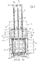
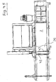
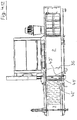
- the FIG. 1 shows the new baler 1 in a perspective side view. It includes inter alia - in the representation from right to left seen in a horizontal orientation - a drive area 5 , one to it subsequent press box 2 , then followed by a press channel 3 connects. Above the press box 2 , a filling opening 4 is provided, which is designed here as a feed chute. In the provided between the press box 2 and the press channel 3 transition section 2a , the Umschnürungsö the new baler is arranged. It consists of an arranged on the top band drawing station 8 and a corresponding thereto under the bottom of the baler 39 arranged Bandleitstation 7. The other components of the band drawing station 8 and the Bandleitstation 7 will be explained in more detail later.
- the stored in a tape supply station tape rolls are stored below the bottom of the baler.
- the tape storage station is provided sideways on the drive area in this new baler. From here, the tape is guided by means of a first tape guide 22 and a second tape guide 23 below the bottom 39 to the Bandleitstation 7 and deflected if necessary. Near the tape supply station 21, two first tape guides 22 are provided in the embodiment shown.
- an apron is provided in the bottom area 39 and sideways on the baler 1 so that the Umschnürungsb selected out there are not affected by the feet of the machine operator or with any other object, such as a broom.
- this area can be covered by a protective hood 19 .
- a safety switch is provided so that when unauthorized opening of the press operation is interrupted.
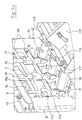
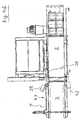
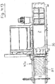
- FIG. 2 Further details and details of the lacing unit 6 are shown and explained.
- the press plate 37 of the baler 1 is in its forward position. The produced bale is pressed and hidden in this view for better clarity.
- vertical grooves 38 are provided whose position correlate with the direction of movement of the tape drawing needles 10 .
- the FIG. 2 is a cross section through the transition portion 2a in the plane of movement of the tape drawing needles.
- the band drawing station 8 is arranged on the top of the baler 1 . It consists of the two side parts 14 and a truss 13 supported on these side parts 14 .
- the proposed hydraulic cylinder 9 here three pieces, fixed.
- corresponding through holes are provided through which the piston rods of the hydraulic cylinder 9 , the pulling needles 10, during their downward or upward movement can pass through.
- head parts 11 are provided at the free ends of the piston rods / pulling needles 10 . These head parts each have a catch hook 12 at their free end portions. The head part 11 and the catch hook 12 may be one or more parts.
- a guide member 18 is provided between the side members 14 . Corresponding to the position of the head parts and their range of motion portions of the guide member 18 are designed as sliding surfaces 18 a.
- the head parts 11 are parallelepiped-shaped, but may also have any other shape, but it is important only that the sliding surface 18a facing side of the head portion 11 has a flat surface portion, for guidance to the respective sliding surface 18 a.
- the guide surface on the head part 11 and the sliding surface 18 a together form a rotation.
- the length of the sliding surface 18 a is such that until immersion of the head parts 11 in the respective leading vertical groove 38 of the pressing plate 13 selbige 11 is guided against rotation. From this position down to the lower position of the pulling needle securing against rotation of the fishing hook 12 is made by the respective vertical groove 38 . So that each pulling needle 10 can dive smoothly into the relevant vertical groove 38 , an opening 15 is provided in the transition section 2a at the top of the baler 1 and in the bottom 39 a passage 17th Below the ground 39 and under the passages 17 is a guide rod 24 , the bottom arranged Bandleitstation 7 , which will be explained later in further details. You can also see the second tape guide 23 .
- ceramic sleeves are provided on the first band guide 22 , the second band guide 23 and the guide rod 24 according to the intended number of strapping bands.
- the ceramic sleeves serve to guide and deflect the respective band.
- At the entrance of the openings 15 are spaced from each other two guide plates 16 are provided with which the threading of the head parts 11 is facilitated in the respective vertical groove 38 .
- these guide straps 16 prevent the usually acute-angled ends of the head parts from being damaged when passing through the opening 15 arranged above the respective vertical groove.
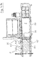
- FIG. 2 a shows further details of the band drawing station 8 .
- a through hole 11 b is provided in each head part 11 .
- the through holes 11 b of each provided head part 11 are aligned with each other.
- an optical sensor unit for example, a light barrier with a receiver and a transmitter is arranged.
- This light cabinet or its components are known in the art and therefore not shown here in the drawing. They are with respect to the position of the head parts 11 arranged so that only when all provided head parts 11 are in their home position and rest position, the transmitter receives a signal to the receiver and from this a sound signal is generated. Only when such a sound signal is present, the drive of the pressure plate is released, so that a pressing stroke can be performed.
- Umschnürungsaku 6 also includes near the provided at the top of the baler 1 openings 15 guide holes 45 , here according to the intended number of three bands three pieces. These guide holes 45 serve the temporary fixing of the ends of the respective band portion. Further details will be given later. In the vicinity of these guide holes 45 , one or more cutting elements 46 are arranged, with each one of the underside of the baler pulled up so-called belt loop can be cut so that the one end can be made to knot with the other end of a finished pressed bale band.
- the safety switch of the protective hood 19 which is to be seen in this view, has the reference numeral 47.
- FIGS. 1 . 2 and 2a are known per se and for at least partially automatic operation of a baler necessary further known components, each a hydraulic motor, a controller for the hydraulics, a controller for the electrically driven parts of the baler and the electronic control unit not shown or not provided with a reference numeral Since these are provided in the usual number and with their usual function and therefore need not be further described here.
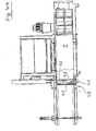
- FIG. 2 shows the tape drawing station 8 and its pulling needles 10 in a waiting position.
- the direction of movement is marked, in which the pulling needles 10 for detecting the Umschnürungsmaterials 20 move.
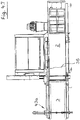
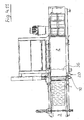
- a bale (see. Figure 4.9 ) is produced with a predetermined bale length or after reaching a number of predetermined pressing strokes of the punch remains 36 at the beginning of the press channel 3 in a front, the end position of a pressing stroke temporarily, so that still pressure is applied to the compressed into a bale waste material (see. Figure 4.9 ).
- the portions of the necking material 20 pulled up by means of the pulling needles 10 are then joined to the portion of the necking material 20 adjacent the top of the formed bale; the details of this will be discussed later in connection with the illustrations in the FIGS. 4 , 1 to 4.16 are explained in detail.
- FIGS. 4 , 1 to 4.16 The operations for positioning the necking material 20 on the baler 1 prior to performing the first press stroke, for strapping a bale B, and for positioning the necking material 20 prior to the first press stroke to make another bale B are as shown in FIGS FIGS. 4 , 1 to 4.16 shown schematically.
- the Umschnürungsmaterial is stored in a tape supply station 21 , which, in this embodiment, the side of the drive portion 5 of the baler 1 is.
- a plastic strip 20 is used as Umschnürungmaterial, said plastic strip 20 has a flat, substantially rectangular cross section, but is not set to this cross section.
- the cross-section of the necking material may be round, elliptical, half-round or another cross-sectional shape.
- the free end 40 of a plastic strip 20 is withdrawn from the stored in the stripper station 21 tape reel and guided over a first tape guide 22 and a second tape guide 23 below and / or side of the bottom 39 of the baler 1 to a Bandleitstation 7 and fixed there, see , For this FIGS. 4 , 1 and 4.2 , This Bandleitstation 7 is part of the Umschnürungs Maschinen 6 ; it will be described in detail later.
- This position P corresponds approximately to the length of a pressed in the pressing channel 3 bale.
- the position P also defines the position of the front surface of a finished bale B.
- clamping bodies 35 are provided in a corresponding number in the area of the passages for the Umschnürungsmaterial. In the positioning of the section 43 , the clamping body 35 is "open” in one position and is closed after the positioning of said section 43 .
- the first bale B 1 is then pressed until its front surface reaches the position P in the pressing channel 3 .
- the portion, the length between this position P and the front of the press plate 37 is the length of a bale B.
- This length can be adjusted depending on the design of the baler or according to the material to be pressed material or mixture of waste by the operator of the baler or it is stored in the control unit of the baler 1 and is automatically retrieved while entering the type of material to be pressed waste at the control unit.
- the now free portion 42 ' is passed through a ball-side slot in the pressure plate 37 (not shown here) and applied to the rear, the pressing plate 37 facing surface of the bale B1 and knotted in its upper edge region with the free end 43 a of the belt portion 43 or twisted, depending on what kind of Umschnürungsmaterial is.
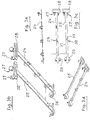
- Bandleitstation 7 For a good handling of the Umschürungsmaterial when positioning before the first pressing stroke and the knot on the finished pressed bale B arranged below the bottom 39 Bandleitstation 7 is specially designed, the details of which are in the FIGS. 3a . 3b, 3c, 3d and 3e shown in different views. In a new, inventive design belonging to this Bandleitstation 7 a guide rod 24 and a mounting rod 25 , which are arranged under the bottom 39 of the baler 1 in the region of the feedthroughs for the pulling needles 10 .
- the guide rod 24 is aligned to the press box 2 and the mounting rod 25 to the pressing channel 3 aligned and releasably secured transversely to the feed direction of the punch 36 under the bottom 39 .
- a latching part 26 is fixed on one side of the bottom 39 in each case.
- the guide rod 24 and the mounting rod 25 have at one end a handle 28 and two upwardly directed tabs 27 , the opposite end of the two components 24 , 25 is free. These free ends are inserted to set each in one of the remaining parts 26 and with its other end by means of the tabs 27 on the other side of the bottom 39 , see.
- FIG. 1 detachably fastened.
- one of the tabs 27 is placed on a bolt provided on the body of the baler and then set the held in the second tabs 27 threaded screw on the body.
- the guide rod 24 also has guide rings 29 , through which the coming of the second tape guide 23 plastic tape 20 is passed to fix its end 40 to a notch 30 and holes 31 of the mounting rod 25 .
- guide plates 32 are arranged on the bottom 39 in the region with which the plastic band 20 is guided in a position which facilitates grasping of selbigem by the free ends of the pulling pins 10 degrees.
Landscapes
- Engineering & Computer Science (AREA)
- Mechanical Engineering (AREA)
- Life Sciences & Earth Sciences (AREA)
- Environmental Sciences (AREA)
- Basic Packing Technique (AREA)
Claims (8)
- Presse à balles pour le compactage de matériau en vrac et pour le ficelage du matériau compacté en balle, comprenant- un caisson de compression (2), qui présente une ouverture de remplissage (4), à travers laquelle parvient le matériau en vrac dans le caisson de compression (2),- un canal de compression horizontal (3) dans le sens de la sortie du caisson de compression (2),- un piston de compression (36) mobile entre une position de sortie à travers le caisson de compression (2) jusqu'à proximité du début du canal de compression (3) et une position avant à l'horizontale, avec une rainure verticale (38) dans la surface frontale de la plaque de compression (37) disposée sur la face frontale sur le piston de compression (36), ainsi- qu'une unité de ficelage (6) avec des aiguilles cibles (10) pour le cerclage d'une balle compressée (B) avec du matériau de ficelage (20),- l'unité de ficelage (4) comprenant un poste de tirage de bande (8) disposé sur la face supérieure et un poste de guidage de bande (7) disposé en dessous du fond de la presse à balles (39),- l'unité de ficelage (6) étant disposée à l'extérieur du caisson de compresson (2) dans la section de transition (2a) entre le canal de compression (2) et le canal de compression (3),- la position des rainures verticales (38) étant corrélée avec la direction de déplacement des aiguilles cibles (10), quand la plaque de compression (37) se trouve dans la presse à balles (1) dans sa position avant,- des ouvertures (15) étant prévues pour le passage des aiguilles cibles (10) dans la face supérieure de la presse,- une partie de tête (11) étant disposée respectivement sur les extrémités libres des aiguilles cibles, qui sont prévues pour saisir le matériel de ficelage (20), les parties de tête (11) présentant sur leur section libre respectivelent un crochet de capture (12), caractarisée en ce- que la surface de glisse (18a) réalisée sur une partie de guidage (18) de poste de tirage de bande (8) et la surface de guidage respective forment ensemble sur la partie de tête (11) une sécurité anti-rotation,- la longueur de la surface de glisse (18a) étant prévue pour que la partie de tête (11) soit guidée sans rotation jusqu'à ce qu'elle pénètre dans la rainure verticale (38) de guidage de la plaque de compression (13) et- la sécurité anti-rotation du crochet de capture (12) est assurée par la rainure verticale concernée (38) à partir de cette position jusqu'à la position inférieure de l'aiguille cible (10),- de sorte que les crochets de capture (12) prévus sur les parties de tête (11) prennent constamment du début à la fin de leur déplacement une position définie pour tirer vers le haut une portion du matériau de ficelage (20).
- Presse à balles selon l'une des revendications précédentes, dans laquelle chaque partie de tête (11) présente au moins une surface plane, qui est en contact avec des surfaces de glisse opposées au repos afin d'assurer un guidage droit et une sécurité anti-rotation.
- Presse à balles selon la revendication 1 ou 2, dans laquelle le guidage droit et la sécurité anti-rotation des parties de tête (11) sont prévus- au-dessus du canal de compression (3) au moyen d'une partie de guidage (18) sur laquelle sont réalisées des surfaces de glisse (18a) qui sont opposées aux surfaces de glisse sur les parties de tête (11), et- à l'intérieur du canal de compression (3) au moyen de rainures verticales (38) munies de surfaces de glisse ménagées dans le piston de compression (36).
- Presse à balles selon l'une des revendications précédentes, dans laquelle Il est prévu dans la zone de déplacement des parties de tête (11)- des ouvertures (15) dans la section de transition de la face supérieure de la presse à balles (1) à l'intérieur du canal de compression (3), et- des passages (17) pour les parties de tête (11) y compris les crochets de capture (12) dans la section de transiton du canal de compression (3) vers la zone en dessous du fond (39) de la presse à balles.
- Presse à balles selon la revendication 4, dans laquelle les ouvertures (15) sont munies de languettes de guidage (16) inclinées les unes vers les autres pour faciliter le glissement des parties de tête (11) dans la rainure verticale associée (38) et éviter d'endommager les crochets de capture (12).
- Presse à balles selon l'une des revendications précédentes, dans laquelle plusieurs de préférence trois aiguilles cibles (10) sont disposées parallélement entre elles et sont reliées par une commande commune pour le déplacement ascendant et descendant, des vérins hydraulyques (9) étant prévus pour l'entraînement des aiguilles cibles (10).
- Presse à balles selon la revendication 6, munie d'un dispositif de sécurité qui est réalisé par rapport à la position et l'orientation des parties de tête (11) de sorte que le déplacement du piston de compression (36) ne peut être déclenché que quand toutes les parties de tête (11) se trouvent dans une position de repos prescrite en amont du canal de compression (3).
- Presse à balles selon l'une des revendications précédentes, dans laquelle la longueur des balles (B) est variable dans la direction de compression, caractérisée par- des éléments de coupe (46) pour le sectionnement des boucles (41, 41) après la sortie hors de la face supérieure (3a) du canal de de compression (3), et- des moyens pour tirer les extrémités des boucles (41, 41'), qui sont reliées après le sectionnement à une réserve de matériau de ficellage (20) dans la direction de compression parallèment à la face supérieure (3a) jusqu'à une position (P) qui est définie par une longueur prédéterminée respective des balles (B) dans la direction de compression.
Priority Applications (1)
| Application Number | Priority Date | Filing Date | Title |
|---|---|---|---|
| EP12158101.1A EP2478757B1 (fr) | 2010-09-03 | 2010-09-03 | Presse à empaqueter |
Applications Claiming Priority (2)
| Application Number | Priority Date | Filing Date | Title |
|---|---|---|---|
| EP12158101.1A EP2478757B1 (fr) | 2010-09-03 | 2010-09-03 | Presse à empaqueter |
| EP10009152A EP2425704A3 (fr) | 2010-09-03 | 2010-09-03 | Presse à paquet et procédé destiné à ceindre des paquets dans celle-ci |
Related Parent Applications (2)
| Application Number | Title | Priority Date | Filing Date |
|---|---|---|---|
| EP10009152A Division EP2425704A3 (fr) | 2010-09-03 | 2010-09-03 | Presse à paquet et procédé destiné à ceindre des paquets dans celle-ci |
| EP10009152.9 Division | 2010-09-03 |
Publications (2)
| Publication Number | Publication Date |
|---|---|
| EP2478757A1 EP2478757A1 (fr) | 2012-07-25 |
| EP2478757B1 true EP2478757B1 (fr) | 2017-11-08 |
Family
ID=44718996
Family Applications (2)
| Application Number | Title | Priority Date | Filing Date |
|---|---|---|---|
| EP12158101.1A Active EP2478757B1 (fr) | 2010-09-03 | 2010-09-03 | Presse à empaqueter |
| EP10009152A Withdrawn EP2425704A3 (fr) | 2010-09-03 | 2010-09-03 | Presse à paquet et procédé destiné à ceindre des paquets dans celle-ci |
Family Applications After (1)
| Application Number | Title | Priority Date | Filing Date |
|---|---|---|---|
| EP10009152A Withdrawn EP2425704A3 (fr) | 2010-09-03 | 2010-09-03 | Presse à paquet et procédé destiné à ceindre des paquets dans celle-ci |
Country Status (1)
| Country | Link |
|---|---|
| EP (2) | EP2478757B1 (fr) |
Cited By (1)
| Publication number | Priority date | Publication date | Assignee | Title |
|---|---|---|---|---|
| EP4261028A1 (fr) * | 2022-04-04 | 2023-10-18 | Unotech GmbH | Presse à balles à canal avec arrêt croisé |
Families Citing this family (2)
| Publication number | Priority date | Publication date | Assignee | Title |
|---|---|---|---|---|
| WO2014076322A1 (fr) * | 2012-11-16 | 2014-05-22 | García Navarro Rafael | Machine à ficeler les ballots à haute précision et procédé de ficelage |
| PL3323284T3 (pl) | 2016-11-21 | 2020-03-31 | Bollegraaf Patents And Brands B.V. | Prasa belująca i sposób prasowania i wiązania beli w prasie belującej |
Family Cites Families (10)
| Publication number | Priority date | Publication date | Assignee | Title |
|---|---|---|---|---|
| DE2105163C3 (de) * | 1971-02-04 | 1974-02-28 | Paal's Packpressen-Fabrik Kg, 4500 Osnabrueck | Maschine zum Pressen und Umschnüren von Ballen mit Draht |
| DE2419151A1 (de) | 1974-04-20 | 1975-11-06 | Lindemann Maschfab Gmbh | Vorrichtung zum umschnueren von ballen |
| DE2460464C3 (de) * | 1974-12-20 | 1981-11-26 | Lindemann Maschinenfabrik GmbH, 4000 Düsseldorf | Umschnürungsvorrichtung an einer Ballenpresse |
| DE2504059C2 (de) | 1975-01-31 | 1985-07-11 | Lindemann Maschinenfabrik GmbH, 4000 Düsseldorf | Zuführfüllschacht |
| DE2540452A1 (de) * | 1975-09-11 | 1977-03-17 | Lindemann Maschfab Gmbh | Verfahren und vorrichtung zum umschnueren von in einer kastenpresse hergestellten ballen aus mindestens vorwiegend nichtmetallischem stoff |
| DE2728203C3 (de) | 1977-06-23 | 1981-11-19 | Lindemann Maschinenfabrik GmbH, 4000 Düsseldorf | Ballenpresse mit einem mehrere Schnürnuten aufweisenden Preßstempel |
| DE3202233A1 (de) * | 1982-01-25 | 1983-08-04 | Lindemann Maschinenfabrik GmbH, 4000 Düsseldorf | Vorrichtung zum umschnueren von ballen |
| DE3918065A1 (de) | 1989-06-02 | 1990-12-06 | Lindemann Maschfab Gmbh | Vorrichtung zum umschnueren von in einer ballenpresse hergestellten ballen |
| DE10047336A1 (de) | 2000-09-23 | 2002-04-11 | Paals Packpressen Fabrik Gmbh | Ballenpresse für loses Preßgut |
| EP1785351A1 (fr) | 2005-11-09 | 2007-05-16 | Machinefabriek Bollegraaf Appingedam B.V. | Méthode, dispositif et enrouler pour attacher les extrémités d'un fil qui entoure une balle |
-
2010
- 2010-09-03 EP EP12158101.1A patent/EP2478757B1/fr active Active
- 2010-09-03 EP EP10009152A patent/EP2425704A3/fr not_active Withdrawn
Non-Patent Citations (1)
| Title |
|---|
| None * |
Cited By (2)
| Publication number | Priority date | Publication date | Assignee | Title |
|---|---|---|---|---|
| EP4261028A1 (fr) * | 2022-04-04 | 2023-10-18 | Unotech GmbH | Presse à balles à canal avec arrêt croisé |
| EP4331828A1 (fr) * | 2022-04-04 | 2024-03-06 | Unotech GmbH | Presse à balles à canal avec arrêt croisé |
Also Published As
| Publication number | Publication date |
|---|---|
| EP2478757A1 (fr) | 2012-07-25 |
| EP2425704A2 (fr) | 2012-03-07 |
| EP2425704A3 (fr) | 2012-03-14 |
Similar Documents
| Publication | Publication Date | Title |
|---|---|---|
| DE2709248C2 (de) | Verfahren und Vorrichtung zum Umschnüren von Ballen | |
| EP0084680B1 (fr) | Appareil pour lier des balles dans une presse à balles | |
| DE2656457C3 (de) | Ballenpresse | |
| EP3323603B1 (fr) | Presse à balle horizontale pourvue d'un dispositif de ficelage des ballots | |
| DE2460464A1 (de) | Vorrichtung zum umschnueren von ballen aus vorwiegend nichtmetallischem material | |
| EP2478757B1 (fr) | Presse à empaqueter | |
| EP3199331B1 (fr) | Presse à balles | |
| DE102012008554A1 (de) | Kanalballenpresse | |
| DE10047336A1 (de) | Ballenpresse für loses Preßgut | |
| EP2628591B1 (fr) | Presse destinée à la fabrication de balles compactées | |
| DE102009040506B4 (de) | Ballenpresse | |
| EP4091808B1 (fr) | Procédé de changement de cerclage, ainsi que presse à balles destinée à l'utilisation du procédé | |
| EP2660160A2 (fr) | Presse à paquet à canal | |
| EP3326451B1 (fr) | Presse à balles pour matière à presser en vrac | |
| DE202010017707U1 (de) | Ballenpresse | |
| DE102016117755A1 (de) | Verfahren zum Steuern der Ballen-Länge sowie Ballenpresse zur Anwendung dieses Verfahrens | |
| EP1683408B1 (fr) | Presse à balles | |
| DE10131165A1 (de) | Verfahren und Vorrichtung zum Abbinden eines Ballens in Ballenpressen | |
| DE2552064B2 (de) | Verschnürungsvorrichtung für Ballenpressen | |
| EP1234495B1 (fr) | Presse-botteleuse avec dispositif de liage | |
| AT406454B (de) | Vorrichtung zum abbinden von mehreren, im wesentlichen übereinanderliegenden gegenständen | |
| EP0400380A1 (fr) | Appareil pour cercler des balles faites dans une presse à balles | |
| EP3907065B1 (fr) | Presse à balles | |
| EP4331828A1 (fr) | Presse à balles à canal avec arrêt croisé | |
| DE102008010155A1 (de) | Verfahren und Vorrichtung zum Abbinden eines Ballens |
Legal Events
| Date | Code | Title | Description |
|---|---|---|---|
| PUAI | Public reference made under article 153(3) epc to a published international application that has entered the european phase |
Free format text: ORIGINAL CODE: 0009012 |
|
| AC | Divisional application: reference to earlier application |
Ref document number: 2425704 Country of ref document: EP Kind code of ref document: P |
|
| AK | Designated contracting states |
Kind code of ref document: A1 Designated state(s): AL AT BE BG CH CY CZ DE DK EE ES FI FR GB GR HR HU IE IS IT LI LT LU LV MC MK MT NL NO PL PT RO SE SI SK SM TR |
|
| AX | Request for extension of the european patent |
Extension state: BA ME RS |
|
| 17P | Request for examination filed |
Effective date: 20130125 |
|
| 17Q | First examination report despatched |
Effective date: 20140404 |
|
| GRAP | Despatch of communication of intention to grant a patent |
Free format text: ORIGINAL CODE: EPIDOSNIGR1 |
|
| INTG | Intention to grant announced |
Effective date: 20170704 |
|
| GRAS | Grant fee paid |
Free format text: ORIGINAL CODE: EPIDOSNIGR3 |
|
| GRAA | (expected) grant |
Free format text: ORIGINAL CODE: 0009210 |
|
| AC | Divisional application: reference to earlier application |
Ref document number: 2425704 Country of ref document: EP Kind code of ref document: P |
|
| AK | Designated contracting states |
Kind code of ref document: B1 Designated state(s): AL AT BE BG CH CY CZ DE DK EE ES FI FR GB GR HR HU IE IS IT LI LT LU LV MC MK MT NL NO PL PT RO SE SI SK SM TR |
|
| REG | Reference to a national code |
Ref country code: GB Ref legal event code: FG4D Free format text: NOT ENGLISH |
|
| REG | Reference to a national code |
Ref country code: CH Ref legal event code: EP Ref country code: AT Ref legal event code: REF Ref document number: 943262 Country of ref document: AT Kind code of ref document: T Effective date: 20171115 |
|
| REG | Reference to a national code |
Ref country code: IE Ref legal event code: FG4D Free format text: LANGUAGE OF EP DOCUMENT: GERMAN |
|
| REG | Reference to a national code |
Ref country code: DE Ref legal event code: R096 Ref document number: 502010014360 Country of ref document: DE |
|
| REG | Reference to a national code |
Ref country code: NL Ref legal event code: MP Effective date: 20171108 |
|
| REG | Reference to a national code |
Ref country code: LT Ref legal event code: MG4D |
|
| PG25 | Lapsed in a contracting state [announced via postgrant information from national office to epo] |
Ref country code: NL Free format text: LAPSE BECAUSE OF FAILURE TO SUBMIT A TRANSLATION OF THE DESCRIPTION OR TO PAY THE FEE WITHIN THE PRESCRIBED TIME-LIMIT Effective date: 20171108 Ref country code: LT Free format text: LAPSE BECAUSE OF FAILURE TO SUBMIT A TRANSLATION OF THE DESCRIPTION OR TO PAY THE FEE WITHIN THE PRESCRIBED TIME-LIMIT Effective date: 20171108 Ref country code: FI Free format text: LAPSE BECAUSE OF FAILURE TO SUBMIT A TRANSLATION OF THE DESCRIPTION OR TO PAY THE FEE WITHIN THE PRESCRIBED TIME-LIMIT Effective date: 20171108 Ref country code: SE Free format text: LAPSE BECAUSE OF FAILURE TO SUBMIT A TRANSLATION OF THE DESCRIPTION OR TO PAY THE FEE WITHIN THE PRESCRIBED TIME-LIMIT Effective date: 20171108 Ref country code: NO Free format text: LAPSE BECAUSE OF FAILURE TO SUBMIT A TRANSLATION OF THE DESCRIPTION OR TO PAY THE FEE WITHIN THE PRESCRIBED TIME-LIMIT Effective date: 20180208 Ref country code: ES Free format text: LAPSE BECAUSE OF FAILURE TO SUBMIT A TRANSLATION OF THE DESCRIPTION OR TO PAY THE FEE WITHIN THE PRESCRIBED TIME-LIMIT Effective date: 20171108 |
|
| PG25 | Lapsed in a contracting state [announced via postgrant information from national office to epo] |
Ref country code: BG Free format text: LAPSE BECAUSE OF FAILURE TO SUBMIT A TRANSLATION OF THE DESCRIPTION OR TO PAY THE FEE WITHIN THE PRESCRIBED TIME-LIMIT Effective date: 20180208 Ref country code: LV Free format text: LAPSE BECAUSE OF FAILURE TO SUBMIT A TRANSLATION OF THE DESCRIPTION OR TO PAY THE FEE WITHIN THE PRESCRIBED TIME-LIMIT Effective date: 20171108 Ref country code: IS Free format text: LAPSE BECAUSE OF FAILURE TO SUBMIT A TRANSLATION OF THE DESCRIPTION OR TO PAY THE FEE WITHIN THE PRESCRIBED TIME-LIMIT Effective date: 20180308 Ref country code: HR Free format text: LAPSE BECAUSE OF FAILURE TO SUBMIT A TRANSLATION OF THE DESCRIPTION OR TO PAY THE FEE WITHIN THE PRESCRIBED TIME-LIMIT Effective date: 20171108 Ref country code: GR Free format text: LAPSE BECAUSE OF FAILURE TO SUBMIT A TRANSLATION OF THE DESCRIPTION OR TO PAY THE FEE WITHIN THE PRESCRIBED TIME-LIMIT Effective date: 20180209 |
|
| PG25 | Lapsed in a contracting state [announced via postgrant information from national office to epo] |
Ref country code: CZ Free format text: LAPSE BECAUSE OF FAILURE TO SUBMIT A TRANSLATION OF THE DESCRIPTION OR TO PAY THE FEE WITHIN THE PRESCRIBED TIME-LIMIT Effective date: 20171108 Ref country code: CY Free format text: LAPSE BECAUSE OF FAILURE TO SUBMIT A TRANSLATION OF THE DESCRIPTION OR TO PAY THE FEE WITHIN THE PRESCRIBED TIME-LIMIT Effective date: 20171108 Ref country code: EE Free format text: LAPSE BECAUSE OF FAILURE TO SUBMIT A TRANSLATION OF THE DESCRIPTION OR TO PAY THE FEE WITHIN THE PRESCRIBED TIME-LIMIT Effective date: 20171108 Ref country code: DK Free format text: LAPSE BECAUSE OF FAILURE TO SUBMIT A TRANSLATION OF THE DESCRIPTION OR TO PAY THE FEE WITHIN THE PRESCRIBED TIME-LIMIT Effective date: 20171108 Ref country code: SK Free format text: LAPSE BECAUSE OF FAILURE TO SUBMIT A TRANSLATION OF THE DESCRIPTION OR TO PAY THE FEE WITHIN THE PRESCRIBED TIME-LIMIT Effective date: 20171108 |
|
| REG | Reference to a national code |
Ref country code: DE Ref legal event code: R097 Ref document number: 502010014360 Country of ref document: DE |
|
| PG25 | Lapsed in a contracting state [announced via postgrant information from national office to epo] |
Ref country code: IT Free format text: LAPSE BECAUSE OF FAILURE TO SUBMIT A TRANSLATION OF THE DESCRIPTION OR TO PAY THE FEE WITHIN THE PRESCRIBED TIME-LIMIT Effective date: 20171108 Ref country code: RO Free format text: LAPSE BECAUSE OF FAILURE TO SUBMIT A TRANSLATION OF THE DESCRIPTION OR TO PAY THE FEE WITHIN THE PRESCRIBED TIME-LIMIT Effective date: 20171108 Ref country code: SM Free format text: LAPSE BECAUSE OF FAILURE TO SUBMIT A TRANSLATION OF THE DESCRIPTION OR TO PAY THE FEE WITHIN THE PRESCRIBED TIME-LIMIT Effective date: 20171108 Ref country code: PL Free format text: LAPSE BECAUSE OF FAILURE TO SUBMIT A TRANSLATION OF THE DESCRIPTION OR TO PAY THE FEE WITHIN THE PRESCRIBED TIME-LIMIT Effective date: 20171108 |
|
| PLBE | No opposition filed within time limit |
Free format text: ORIGINAL CODE: 0009261 |
|
| STAA | Information on the status of an ep patent application or granted ep patent |
Free format text: STATUS: NO OPPOSITION FILED WITHIN TIME LIMIT |
|
| REG | Reference to a national code |
Ref country code: FR Ref legal event code: PLFP Year of fee payment: 9 |
|
| PG25 | Lapsed in a contracting state [announced via postgrant information from national office to epo] |
Ref country code: MT Free format text: LAPSE BECAUSE OF FAILURE TO SUBMIT A TRANSLATION OF THE DESCRIPTION OR TO PAY THE FEE WITHIN THE PRESCRIBED TIME-LIMIT Effective date: 20171108 |
|
| 26N | No opposition filed |
Effective date: 20180809 |
|
| PG25 | Lapsed in a contracting state [announced via postgrant information from national office to epo] |
Ref country code: SI Free format text: LAPSE BECAUSE OF FAILURE TO SUBMIT A TRANSLATION OF THE DESCRIPTION OR TO PAY THE FEE WITHIN THE PRESCRIBED TIME-LIMIT Effective date: 20171108 |
|
| PG25 | Lapsed in a contracting state [announced via postgrant information from national office to epo] |
Ref country code: MC Free format text: LAPSE BECAUSE OF FAILURE TO SUBMIT A TRANSLATION OF THE DESCRIPTION OR TO PAY THE FEE WITHIN THE PRESCRIBED TIME-LIMIT Effective date: 20171108 |
|
| REG | Reference to a national code |
Ref country code: CH Ref legal event code: PL |
|
| REG | Reference to a national code |
Ref country code: BE Ref legal event code: MM Effective date: 20180930 |
|
| REG | Reference to a national code |
Ref country code: IE Ref legal event code: MM4A |
|
| PG25 | Lapsed in a contracting state [announced via postgrant information from national office to epo] |
Ref country code: LU Free format text: LAPSE BECAUSE OF NON-PAYMENT OF DUE FEES Effective date: 20180903 |
|
| PG25 | Lapsed in a contracting state [announced via postgrant information from national office to epo] |
Ref country code: IE Free format text: LAPSE BECAUSE OF NON-PAYMENT OF DUE FEES Effective date: 20180903 |
|
| PG25 | Lapsed in a contracting state [announced via postgrant information from national office to epo] |
Ref country code: LI Free format text: LAPSE BECAUSE OF NON-PAYMENT OF DUE FEES Effective date: 20180930 Ref country code: CH Free format text: LAPSE BECAUSE OF NON-PAYMENT OF DUE FEES Effective date: 20180930 Ref country code: BE Free format text: LAPSE BECAUSE OF NON-PAYMENT OF DUE FEES Effective date: 20180930 |
|
| REG | Reference to a national code |
Ref country code: AT Ref legal event code: MM01 Ref document number: 943262 Country of ref document: AT Kind code of ref document: T Effective date: 20180903 |
|
| PG25 | Lapsed in a contracting state [announced via postgrant information from national office to epo] |
Ref country code: AT Free format text: LAPSE BECAUSE OF NON-PAYMENT OF DUE FEES Effective date: 20180903 |
|
| PG25 | Lapsed in a contracting state [announced via postgrant information from national office to epo] |
Ref country code: TR Free format text: LAPSE BECAUSE OF FAILURE TO SUBMIT A TRANSLATION OF THE DESCRIPTION OR TO PAY THE FEE WITHIN THE PRESCRIBED TIME-LIMIT Effective date: 20171108 |
|
| PG25 | Lapsed in a contracting state [announced via postgrant information from national office to epo] |
Ref country code: PT Free format text: LAPSE BECAUSE OF FAILURE TO SUBMIT A TRANSLATION OF THE DESCRIPTION OR TO PAY THE FEE WITHIN THE PRESCRIBED TIME-LIMIT Effective date: 20171108 Ref country code: HU Free format text: LAPSE BECAUSE OF FAILURE TO SUBMIT A TRANSLATION OF THE DESCRIPTION OR TO PAY THE FEE WITHIN THE PRESCRIBED TIME-LIMIT; INVALID AB INITIO Effective date: 20100903 |
|
| PG25 | Lapsed in a contracting state [announced via postgrant information from national office to epo] |
Ref country code: MK Free format text: LAPSE BECAUSE OF NON-PAYMENT OF DUE FEES Effective date: 20171108 |
|
| PG25 | Lapsed in a contracting state [announced via postgrant information from national office to epo] |
Ref country code: AL Free format text: LAPSE BECAUSE OF FAILURE TO SUBMIT A TRANSLATION OF THE DESCRIPTION OR TO PAY THE FEE WITHIN THE PRESCRIBED TIME-LIMIT Effective date: 20171108 |
|
| PGFP | Annual fee paid to national office [announced via postgrant information from national office to epo] |
Ref country code: GB Payment date: 20220920 Year of fee payment: 13 Ref country code: DE Payment date: 20220630 Year of fee payment: 13 |
|
| PGFP | Annual fee paid to national office [announced via postgrant information from national office to epo] |
Ref country code: FR Payment date: 20220922 Year of fee payment: 13 |
|
| P01 | Opt-out of the competence of the unified patent court (upc) registered |
Effective date: 20230527 |
|
| REG | Reference to a national code |
Ref country code: DE Ref legal event code: R119 Ref document number: 502010014360 Country of ref document: DE |