EP3326451B1 - Presse à balles pour matière à presser en vrac - Google Patents
Presse à balles pour matière à presser en vrac Download PDFInfo
- Publication number
- EP3326451B1 EP3326451B1 EP17199144.1A EP17199144A EP3326451B1 EP 3326451 B1 EP3326451 B1 EP 3326451B1 EP 17199144 A EP17199144 A EP 17199144A EP 3326451 B1 EP3326451 B1 EP 3326451B1
- Authority
- EP
- European Patent Office
- Prior art keywords
- bale
- pressing
- strapping
- channel
- discharge
- Prior art date
- Legal status (The legal status is an assumption and is not a legal conclusion. Google has not performed a legal analysis and makes no representation as to the accuracy of the status listed.)
- Active
Links
- 239000000463 material Substances 0.000 title claims description 21
- 238000003825 pressing Methods 0.000 claims description 52
- 238000000034 method Methods 0.000 claims description 23
- 239000002184 metal Substances 0.000 claims description 5
- 239000013590 bulk material Substances 0.000 claims 3
- 238000001266 bandaging Methods 0.000 description 37
- 238000007906 compression Methods 0.000 description 11
- 230000006835 compression Effects 0.000 description 10
- 239000013502 plastic waste Substances 0.000 description 4
- 239000010893 paper waste Substances 0.000 description 3
- 238000004519 manufacturing process Methods 0.000 description 2
- 230000027455 binding Effects 0.000 description 1
- 238000009739 binding Methods 0.000 description 1
- 230000015572 biosynthetic process Effects 0.000 description 1
- 239000011111 cardboard Substances 0.000 description 1
- 239000002657 fibrous material Substances 0.000 description 1
- 238000009434 installation Methods 0.000 description 1
- 230000014759 maintenance of location Effects 0.000 description 1
- 239000010812 mixed waste Substances 0.000 description 1
- 239000011087 paperboard Substances 0.000 description 1
- 230000000149 penetrating effect Effects 0.000 description 1
- 238000004064 recycling Methods 0.000 description 1
Images


Classifications
-
- A—HUMAN NECESSITIES
- A01—AGRICULTURE; FORESTRY; ANIMAL HUSBANDRY; HUNTING; TRAPPING; FISHING
- A01F—PROCESSING OF HARVESTED PRODUCE; HAY OR STRAW PRESSES; DEVICES FOR STORING AGRICULTURAL OR HORTICULTURAL PRODUCE
- A01F15/00—Baling presses for straw, hay or the like
- A01F15/08—Details
- A01F15/14—Tying devices specially adapted for baling presses
-
- B—PERFORMING OPERATIONS; TRANSPORTING
- B30—PRESSES
- B30B—PRESSES IN GENERAL
- B30B9/00—Presses specially adapted for particular purposes
- B30B9/30—Presses specially adapted for particular purposes for baling; Compression boxes therefor
- B30B9/3003—Details
-
- B—PERFORMING OPERATIONS; TRANSPORTING
- B30—PRESSES
- B30B—PRESSES IN GENERAL
- B30B9/00—Presses specially adapted for particular purposes
- B30B9/30—Presses specially adapted for particular purposes for baling; Compression boxes therefor
- B30B9/3003—Details
- B30B9/3014—Ejection means
-
- B—PERFORMING OPERATIONS; TRANSPORTING
- B30—PRESSES
- B30B—PRESSES IN GENERAL
- B30B9/00—Presses specially adapted for particular purposes
- B30B9/30—Presses specially adapted for particular purposes for baling; Compression boxes therefor
- B30B9/3078—Presses specially adapted for particular purposes for baling; Compression boxes therefor with precompression means
-
- B—PERFORMING OPERATIONS; TRANSPORTING
- B30—PRESSES
- B30B—PRESSES IN GENERAL
- B30B9/00—Presses specially adapted for particular purposes
- B30B9/30—Presses specially adapted for particular purposes for baling; Compression boxes therefor
- B30B9/3096—Presses specially adapted for particular purposes for baling; Compression boxes therefor the means against which, or wherein, the material is compacted being retractable
-
- B—PERFORMING OPERATIONS; TRANSPORTING
- B65—CONVEYING; PACKING; STORING; HANDLING THIN OR FILAMENTARY MATERIAL
- B65B—MACHINES, APPARATUS OR DEVICES FOR, OR METHODS OF, PACKAGING ARTICLES OR MATERIALS; UNPACKING
- B65B13/00—Bundling articles
- B65B13/18—Details of, or auxiliary devices used in, bundling machines or bundling tools
- B65B13/20—Means for compressing or compacting bundles prior to bundling
-
- B—PERFORMING OPERATIONS; TRANSPORTING
- B65—CONVEYING; PACKING; STORING; HANDLING THIN OR FILAMENTARY MATERIAL
- B65B—MACHINES, APPARATUS OR DEVICES FOR, OR METHODS OF, PACKAGING ARTICLES OR MATERIALS; UNPACKING
- B65B13/00—Bundling articles
- B65B13/18—Details of, or auxiliary devices used in, bundling machines or bundling tools
- B65B13/24—Securing ends of binding material
- B65B13/28—Securing ends of binding material by twisting
-
- B—PERFORMING OPERATIONS; TRANSPORTING
- B65—CONVEYING; PACKING; STORING; HANDLING THIN OR FILAMENTARY MATERIAL
- B65B—MACHINES, APPARATUS OR DEVICES FOR, OR METHODS OF, PACKAGING ARTICLES OR MATERIALS; UNPACKING
- B65B27/00—Bundling particular articles presenting special problems using string, wire, or narrow tape or band; Baling fibrous material, e.g. peat, not otherwise provided for
- B65B27/12—Baling or bundling compressible fibrous material, e.g. peat
-
- B—PERFORMING OPERATIONS; TRANSPORTING
- B65—CONVEYING; PACKING; STORING; HANDLING THIN OR FILAMENTARY MATERIAL
- B65B—MACHINES, APPARATUS OR DEVICES FOR, OR METHODS OF, PACKAGING ARTICLES OR MATERIALS; UNPACKING
- B65B63/00—Auxiliary devices, not otherwise provided for, for operating on articles or materials to be packaged
- B65B63/02—Auxiliary devices, not otherwise provided for, for operating on articles or materials to be packaged for compressing or compacting articles or materials prior to wrapping or insertion in containers or receptacles
Definitions
- the present invention relates to a baler and a method of using the baler.
- Baling presses are used to compress loose material such as paper and cardboard, plastic waste, mixed waste or fiber materials into cuboid bales, which can then be provided with various types of bindings. The bales can then be stacked and transported, the space requirement and the effort involved in handling being significantly reduced.
- baling presses There are different types of baling presses. In addition to channel baling presses with a pressing chamber open on both sides and a subsequent pressing channel in which the bales located there are used as an abutment for the pressing process, there are also the generic baling presses with a pressing chamber open on one side, which are characterized by better shape retention of the bales produced and through a shorter design.
- Generic balers are for example from the DE 69506769 T2 and the DE 20 2012 010 760 U1 known.
- the latter forms the closest prior art, in which the material to be pressed is pressed transversely to the pressing direction into a bale channel after pressing and is gradually conveyed through a bandaging device by a separate feed device.
- the bandaging device straps the bale on its outer circumferential surfaces, that is, based on the conveying direction in the bale channel, on the two side surfaces, the upper side and the lower side. In the conveying direction, the front and back of the bale remain free from bandaging.
- the distance between the bandages on the bale corresponds in each case to the increment that is specified by the conveyor in the bale channel.
- the baling press itself can already carry out further pressing strokes.
- the drive of the press which is usually carried out hydraulically, can simultaneously generate the drive power for the press stroke and for the step-by-step feed in the bale channel.
- the DE 26 56 457 A1 describes a further baling press for loose material to be pressed with a filling chute and a press and discharge ram which conveys the bale after a pressing process in an output direction from a press box, the press box having a slide gate against which the material to be pressed is compressed.
- the document also describes a banding device for strapping the bale formed in the pressing process, which has the bale channel penetrating in the transverse direction through needles.
- the stroke of the pressing and dispensing ram extends behind the lacing needles so that the bale is conveyed through the bandaging device.
- the DE 20 2012 010 760 U1 describes a further baling press in which loose material to be pressed is compressed in a box by means of a press ram, which box is limited during the compression by a sliding wall in the direction of extension behind the box.
- the compression box is spatially located in the discharge channel.
- the ejection takes place by means of an ejection wall. When ejecting, there seems to be no compression, only an extension movement.
- the stroke of the discharge wall ends in the discharge direction just behind the sliding wall in front of a bandaging device.
- the US 2009/272282 A1 describes a baling press in which the loose material to be pressed is compressed in a press channel.
- the compression in the press channel takes place by means of a stamp against the frictional resistance of the bales in the pressing direction behind the pressed material to be compressed, which are already compressed and bundled. Pre-compression takes place via a pivoting flap.
- the EP 2 014 455 A1 describes a baling press in which loose material to be pressed is compressed in a box by means of a press plate, which during the compression is limited by a door that can be opened behind the box in the direction of extension.
- the compression box is spatially located in an area that can be referred to as the discharge channel.
- the ejection takes place by means of an ejection wall. The stroke of the ejection wall ends in the ejection direction shortly after the door to be opened.
- the working stroke of the dispensing ram extends in the dispensing direction to behind the at least one needle of the taping device, so that the dispensing die conveys the bale through the taping device during a full working stroke, separate drivers for conveying the bale in the bale channel can be dispensed with.
- the delivery ram is the only drive for conveying the bale in the delivery direction until the strapping is completed, the omission of the driver makes the press overall simpler. But there are also advantages with regard to the working speed.
- the bandaging device is preferably designed in such a way that it applies bandages to the front end face in the discharge direction and the rear side in the discharge direction as well as to two side surfaces of the bale. This means that the bandaging can be made particularly quickly.
- the bandaging device is set up to apply two or more, in particular four to six bandages simultaneously to the bale, the bale is bandaged particularly tightly without the cycle time being extended as a result.
- the bandaging device is preferably set up to optionally apply bandages made of metal or made of plastic to the bales. Bales can then be produced for different purposes without long changeover times. For example, bales of waste paper can be strapped with wire, while plastic waste can be strapped with a plastic strap. This is advantageous for later recycling. This is made possible by the fact that the bandaging device is arranged in an area of the baler in which it is subject to minor restrictions with regard to space requirements and accessibility.
- the bandaging device is preferably set up to apply the bandages to the bales in the horizontal direction, because then no installation space is required in the vertical direction above or below the bale channel.
- the bandages are drawn off from a number of supply reels.
- the bandaging material can then be varied within certain limits by simply changing the supply reels.
- a method according to the invention is carried out by means of a baling press as described above. Because in a generic method the bale is moved out of the baling chamber in a feed adapted to the banding and by a bandaging device arranged between the baling chamber and the bale channel at least beyond the working area of the needles present in such a bandaging device, the advantages described above are achieved , in particular by eliminating a step for transferring the bale from the dispensing ram to a carrier device.
- the bandaging is preferably carried out on the front face and on the side surfaces during the advance. This increases the possible working speed.
- a compact and maintenance-friendly structure results when the bandaging takes place parallel to a plane that is spanned by the pressing direction and the dispensing direction.
- the working speed is further improved if two or more bandages are produced simultaneously during the bandaging.
- Four to six parallel bandages are preferably provided.
- the two or more bandages are produced from metal wire or plastic wire.
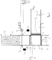
- the Figure 1 shows a baler for loose material to be pressed, such as B. paper or plastic waste as recycled goods, in a plan view.
- the baling press 1 has an upwardly open input area 2 into which the material to be pressed is input, for example via a belt conveyor.
- a press ram 3 can be moved by means of a hydraulic piston / cylinder drive 4 in the direction of a press chamber 5 in a press channel 6, with a press direction 10 having a Direction arrow in Figure 1 is indicated.
- the pressing direction 10 is oriented horizontally in this exemplary embodiment.
- a bale is produced in several working strokes of the ram 3.
- the in Figure 1 The bale shown in the pressing chamber 5 is almost complete.
- the compression chamber 5 is closed on all sides except for the side facing the compression ram 3 so that the compression pressure can be built up.
- the wall on the left in the pressing direction 10 is formed by a dispensing die 12, which also has a hydraulic drive 14 acting in a dispensing direction 13.
- the wall on the right in the pressing direction is formed by a wall part 15 that can be moved in a horizontal direction parallel to the pressing direction 10.
- a further hydraulic drive 16 is assigned to the wall part 15.
- the opening direction is oriented parallel and in the same direction as the pressing direction 10.
- the wall part 15 is in the Figure 1 shown in closed position. It closes the pressing chamber 5 with respect to a bale channel 18.
- the bale channel 18 is oriented transversely to the pressing channel 6 and, starting from the pressing direction 10, runs to the right.
- the ball channel is provided with a bandaging device 20.
- the bandaging device 20 is shown here as a wire tie with two supply reels 21 and 22.
- the wires are fetched by appropriate grippers 23 and a needle 24 in a manner known per se and twisted or knotted. In the top view of the Figure 1 only two wires can be seen. At right angles to the plane of the drawing, however, a plurality of wire pulls arranged in parallel, each with associated grippers and needles, are provided, about three to six depending on the bale size. Further in the discharge direction 13, an already finished and strapped bale 25 is shown in the bale channel 18.
- the Figure 2 shows the baler off Figure 1 in the same view.
- the press ram 3 has moved so far into the press channel 6 in the press direction 10 that the end face of the press ram 3 facing the material to be pressed is essentially aligned with the inner wall of the output channel 18.
- a second bale 26 was pressed.
- the wall part 15 is out of the output channel 18 by actuation of the drive 16 has been moved out, so that the cross section of the output channel 18 in the output direction 13 is free.
- the delivery stamp 12 was in the in Figure 2 Move the position shown.
- the bale 26 was pressed against the wire coming from the supply reel 21 and took it along in the output direction 13.
- the baler is in the Figure 3 in the same view as in the Figures 1 and 2 shown, so in a plan view.
- the position of the ram 3 is opposite Figure 2 unchanged.
- the output punch 12 is opposite to the output direction 13 back in the starting position of the Figure 1 drove.
- the dispensing ram 12 now again forms a delimiting wall of the pressing chamber 5.
- the wall part 15 is also back in the FIG Figure 1
- the starting position shown moves and forms a further wall of the pressing chamber 5 opposite the dispensing ram 12. In this position, the pressing chamber 5 is closed on all sides.
- the ram 3 is ready for another working stroke.
- the needle 24 of the bandaging device 20 is extended transversely through the bale channel 18 and grips with a barb the wire coming from the supply reel 21 between the supply reel 21 and the point at which the wire is inserted into the bale channel 18.
- the second bale 26 sits in the bale channel 18 and is wrapped with wire on its front face, which is front with respect to the discharge direction 13, and on the two long sides.
- the trailing end face of the bale 26 has not yet been strapped.
- a back expansion against the discharge direction 13 takes place only to a small extent, since this direction is oriented transversely to the pressing direction 10 and a back expansion would primarily take place in or against the pressing direction 10.
- Another position in the procedure is in the Figure 4 which in turn is a top view of the baler.
- the ram 3 has been withdrawn against the pressing direction 10, so that the input area 2 is again as in FIG Figure 1 free is.
- the other five side walls of the pressing chamber 5 are also in the starting position.
- the pressing process for producing the next bale in the pressing chamber 5 can therefore run again.
- the needle 24 was returned to the starting position of FIG Figure 1 proceed, the wire coming from the supply spool 21 being pulled across the bale channel 18. Since the needle 24 with the barb is pulled back into the bandaging device 20 so far that it also penetrates the course of the wire coming from the supply reel 22, this wire is also carried along a little in the direction of the bandaging device 20.
- the bandaging process has already been completed.
- the grippers 23 have gripped and twisted the wire sections lying in front of and behind the needle 24 in relation to the output direction 13, each gripper 23 having its own twisted area for connecting the wires drawn off from the supply reels 21 and 22.
- the wires were cut between the two twisted areas.
- bale 26 is thus completed and sits in the bale channel 18, where it serves as a resistance for the next bale, which is a partial bale 27 in Fig. 5 is indicated.
- each bale 26 is provided with a total of five bandages which wrap around the bale on its front side, its two long sides and its rear side, based on the dispensing direction 13, and thus keep it in shape.
- the press ram 3 is initially in its initial position, which is fixed against the press direction 10. This position is in the Figures 1 , 4th and 5 shown.
- Loose material to be pressed can now be placed in input area 2.
- the material to be pressed is pressed into the pressing chamber 5 by the press ram 3 in one working stroke, where it forms a first partial bale which fills, for example, 20% of the pressing chamber 5. Four more strokes then fill the baling chamber to almost 100%.
- the ram 3 After the last working stroke, the ram 3 remains in the in Figure 2 The position shown and the wall part 15 is moved out of the bale channel 18 by the drive 16, so that the pressing chamber 5 opens towards the bale channel 18.
- the dispensing ram 12 is then moved in the dispensing direction 13 by the drive 14 and pushes the bale that has just been produced into the bale channel 18, to the extent that the rear face of the bale comes behind the working area of the needle 24.
- the bale moved forward in the bale channel 18 takes the wire coming from the supply reel 21 with it, as well as the wire coming from the supply reel 22, since the two wires are connected to one another by a twist.
- the total of five needles 24 in this exemplary embodiment execute their working stroke transversely through the bale channel 18 as soon as the backward movement of the press ram 12 releases the area of the bale channel 18 required for this.
- a barb per needle 24 engages behind the wire coming from the supply roll 21 and pulls it during the backward movement across the bale channel 18.
- the second wire coming from the supply roll 22 is also taken along.
- Each needle 24 is assigned two grippers 23, which now grasp and twist the wires lying in front of and behind the needle. Then cut like wires between the two twists. The ball formation and bandaging process is now complete.
- a major advantage of this baler is that the bandaging process is carried out in the bale channel, specifically at a position that does not interfere with the press chamber and in particular with the movable wall part of the press chamber. The baling of the next bale can therefore already begin when the banding has not yet been completed. It can be seen that this shortens the cycle time of the baling press and increases throughput.
- bandages with metal wire can be provided, but bandages with bands or monofilaments made of plastic can also be provided.
- bandaging device 20 is a self-contained assembly and the location of the bandaging allows freedom in the arrangement, various bandaging devices can also be provided which can either remain permanently installed and can be controlled as required, or which can be exchanged as an assembly in a short time . In this way, the type of bandaging can be adapted to the changed requirements of the customer or the material to be pressed.
Landscapes
- Engineering & Computer Science (AREA)
- Mechanical Engineering (AREA)
- Life Sciences & Earth Sciences (AREA)
- Environmental Sciences (AREA)
- Basic Packing Technique (AREA)
Claims (13)
- Presse (1) à balles, conçue pour une matière en vrac à comprimer, comprenant- une zone d'introduction (2) et- un bloc presseur (3) agencé pour presser ladite matière à comprimer à partir de ladite zone d'introduction (2), dans une direction de pressage (10), jusque dans une chambre de pressage (5) ouverte d'un côté,- un bloc distributeur (12) qui, à l'issue de l'opération de pressage, convoie la balle (25, 26) hors de ladite chambre de pressage (5) dans une direction de délivrance (13),- un canal (18) à balles, muni d'un orifice d'entrée et d'un orifice de sortie et partant de la chambre de pressage (5) dans la direction de délivrance (13), transversalement par rapport à la direction de pressage (10),- laquelle chambre de pressage (5) est pourvue d'une paroi latérale (15) tournée vers ledit orifice d'entrée du canal (18) à balles, et conçue pour être ouverte à l'issue de l'opération de pressage,- et un dispositif de cerclage (20) qui, destiné à enlacer la balle (25, 26) mise en forme au cours de l'opération de pressage, est doté d'au moins une aiguille (24) traversant ledit canal à balles dans la direction transversale, lors d'une course de travail,
sachant que- la course de travail du bloc distributeur (12) s'étend, dans la direction de délivrance (13), jusque derrière l'aiguille (24) du dispositif de cerclage (20), à présence minimale, de telle sorte que ledit bloc distributeur (12) convoie la balle (25, 26) à travers ledit dispositif de cerclage (20). - Presse à balles selon la revendication 1, caractérisée par le fait que le dispositif de cerclage (20) est interposé, dans la direction de délivrance (13), entre l'orifice d'entrée et l'orifice de sortie du canal (18) à balles.
- Presse à balles selon l'une des revendications précédentes, caractérisée par le fait que le bloc distributeur (12) constitue l'unique entraînement affecté au convoyage de la balle (25, 26), dans la direction de délivrance (13), jusqu'à l'achèvement de l'enlacement.
- Presse à balles selon l'une des revendications précédentes, caractérisée par le fait que le dispositif de cerclage (20) pose des cerclages sur la face frontale située à l'avant dans la direction de délivrance (13) et sur la face postérieure située à l'arrière dans ladite direction de délivrance, ainsi que sur deux surfaces latérales de la balle (25, 26).
- Presse à balles selon l'une des revendications précédentes, caractérisée par le fait que le dispositif de cerclage (20) est agencé pour poser simultanément, sur les balles (25, 26), des cerclages au nombre de deux ou plus.
- Presse à balles selon l'une des revendications précédentes, caractérisée par le fait que le dispositif de cerclage (20) est agencé pour poser sélectivement, sur les balles (25, 26), des cerclages en métal ou en une matière plastique.
- Presse à balles selon l'une des revendications précédentes, caractérisée par le fait que le dispositif de cerclage (20) est agencé pour poser les cerclages sur les balles (25, 26) dans la direction horizontale.
- Presse à balles selon l'une des revendications précédentes, caractérisée par le fait que les cerclages sont dévidés à partir d'un certain nombre de bobines de réserve (21, 22).
- Procédé dévolu au pressage d'une matière en vrac à comprimer en vue de produire des balles (25, 26), et au cerclage des balles (25, 26) comprimées, au moyen d'une presse à balles conforme à l'une des revendications 1-8, dans lequel la matière à comprimer délivrée en vrac est comprimée en des balles (25, 26), suivant une direction de pressage (10) préétablie, jusque dans une chambre de pressage (5) devant être ouverte latéralement, puis est expulsée au moyen d'un bloc distributeur (12), transversalement par rapport à ladite direction de pressage (10), jusque dans un canal (18) à balles et vers un dispositif de cerclage (20), caractérisé par le fait que la balle (25, 26) est mue, suivant une avance coordonnée avec le cerclage, hors de la chambre de pressage (5) et à travers un dispositif de cerclage (20) interposé entre ladite chambre de pressage (5) et ledit canal (18) à balles.
- Procédé selon la revendication 9, caractérisé par le fait que le cerclage a lieu, au cours de l'avance, au niveau de la face frontale antérieure et des surfaces latérales.
- Procédé selon la revendication 9 ou 10, caractérisé par le fait que le cerclage a lieu parallèlement à un plan dont l'étendue est couverte par la direction de pressage (10) et par la direction de délivrance (13).
- Procédé selon l'une des revendications 9 à 11 précédentes, caractérisé par le fait que des cerclages, au nombre de deux ou plus, sont produits simultanément au cours du cerclage.
- Procédé selon l'une des revendications 9 à 12 précédentes, caractérisé par le fait que les cerclages, au nombre de deux ou plus, sont produits à partir d'un fil métallique ou d'un fil en matière plastique.
Priority Applications (1)
| Application Number | Priority Date | Filing Date | Title |
|---|---|---|---|
| PL17199144T PL3326451T3 (pl) | 2016-11-29 | 2017-10-30 | Prasa do belowania do luźnego materiału prasowanego |
Applications Claiming Priority (1)
| Application Number | Priority Date | Filing Date | Title |
|---|---|---|---|
| DE102016014198.0A DE102016014198A1 (de) | 2016-11-29 | 2016-11-29 | Ballenpresse für loses Pressgut |
Publications (2)
| Publication Number | Publication Date |
|---|---|
| EP3326451A1 EP3326451A1 (fr) | 2018-05-30 |
| EP3326451B1 true EP3326451B1 (fr) | 2021-11-24 |
Family
ID=60191249
Family Applications (1)
| Application Number | Title | Priority Date | Filing Date |
|---|---|---|---|
| EP17199144.1A Active EP3326451B1 (fr) | 2016-11-29 | 2017-10-30 | Presse à balles pour matière à presser en vrac |
Country Status (4)
| Country | Link |
|---|---|
| EP (1) | EP3326451B1 (fr) |
| DE (1) | DE102016014198A1 (fr) |
| ES (1) | ES2906642T3 (fr) |
| PL (1) | PL3326451T3 (fr) |
Families Citing this family (1)
| Publication number | Priority date | Publication date | Assignee | Title |
|---|---|---|---|---|
| CN113998179B (zh) * | 2021-11-01 | 2023-02-21 | 安徽银山阻燃新材料科技有限公司 | 一种对前脱脂水刺无纺布生产用原料打包的打包设备 |
Family Cites Families (7)
| Publication number | Priority date | Publication date | Assignee | Title |
|---|---|---|---|---|
| DD96045A1 (de) * | 1972-04-26 | 1973-03-05 | Horizontale hochleistungs-ballenpresse, vorzugsweise für papier- und textilabfälle alle art | |
| DE2656457C3 (de) * | 1976-12-14 | 1981-04-16 | Lindemann Maschinenfabrik GmbH, 4000 Düsseldorf | Ballenpresse |
| ES2112124B1 (es) | 1994-04-15 | 1998-10-01 | Lopez Ramirez Miguel | Procedimiento para la confeccion de balas de materiales disgregados y aparato para su realizacion. |
| DE4416584A1 (de) * | 1994-05-11 | 1995-11-16 | Lindemann Maschfab Gmbh | Verfahren zum Betreiben einer Ballenpresse und Ballenpresse |
| EP2014455B1 (fr) * | 2007-07-13 | 2014-08-20 | Amadeo Farell S.A.U. | Machine pour la fabrication de balles de matériaux désagrégés |
| CA2630694A1 (fr) * | 2008-05-02 | 2009-11-02 | Industries Machinex Inc. | Presse a balles a un piston |
| DE202012010760U1 (de) | 2012-11-12 | 2014-02-14 | Unotech Gmbh | Ballenpresse für loses Pressgut |
-
2016
- 2016-11-29 DE DE102016014198.0A patent/DE102016014198A1/de not_active Withdrawn
-
2017
- 2017-10-30 PL PL17199144T patent/PL3326451T3/pl unknown
- 2017-10-30 ES ES17199144T patent/ES2906642T3/es active Active
- 2017-10-30 EP EP17199144.1A patent/EP3326451B1/fr active Active
Non-Patent Citations (1)
| Title |
|---|
| None * |
Also Published As
| Publication number | Publication date |
|---|---|
| ES2906642T3 (es) | 2022-04-19 |
| EP3326451A1 (fr) | 2018-05-30 |
| DE102016014198A1 (de) | 2018-05-30 |
| PL3326451T3 (pl) | 2022-05-02 |
Similar Documents
| Publication | Publication Date | Title |
|---|---|---|
| EP2668027A1 (fr) | Presse à balles et procédé de production de balles de matière fibreuse comprimées | |
| DE2709248C2 (de) | Verfahren und Vorrichtung zum Umschnüren von Ballen | |
| WO2014072028A1 (fr) | Presse à balles destinée à presser des matières en vrac | |
| EP1922210A1 (fr) | Procede et dispositif de production de balles pressees | |
| EP1190618B1 (fr) | Presse à balles pour matériau non-aggloméré | |
| EP3199331B1 (fr) | Presse à balles | |
| DE102012008554A1 (de) | Kanalballenpresse | |
| EP3326451B1 (fr) | Presse à balles pour matière à presser en vrac | |
| DE102005003397A1 (de) | Kanalballenpresse | |
| EP3665086B1 (fr) | Dispositif d'emballage et procédé d'emballage | |
| EP2478757B1 (fr) | Presse à empaqueter | |
| EP4091808B1 (fr) | Procédé de changement de cerclage, ainsi que presse à balles destinée à l'utilisation du procédé | |
| DE102017010639B4 (de) | Presse und Verfahren zur Erzeugung von rechteckigen Ballen | |
| DE102009040506B4 (de) | Ballenpresse | |
| DE102012202437A1 (de) | Presse zum Herstellen von Pressballen, Abbindeeinrichtung und Nachpresseinrichtung | |
| EP2660160A2 (fr) | Presse à paquet à canal | |
| DE102005042217A1 (de) | Verfahren und Vorrichtung zur Herstellung von Pressballen | |
| DE10111829B4 (de) | Vorrichtung und Verfahren zum Pressen von mindestens einem Fasermaterialkörper | |
| DE4022324A1 (de) | Ballenpresse zum erstellen hochverdichteter, abgebundener ballen aus abfallmaterialien | |
| EP4331828A1 (fr) | Presse à balles à canal avec arrêt croisé | |
| EP0589257A1 (fr) | Presse à balles, notamment pour la compactage de matériaux d'emballage | |
| EP1254840B1 (fr) | Presse pour balles | |
| DE4203360A1 (de) | Vorrichtung zum abbinden von pressballen mit hilfe von bindematerial | |
| DE102022121422A1 (de) | Verfahren zum Verändern der Umreifung sowie Ballenpresse zur Anwendung dieses Verfahrens | |
| DE2308232A1 (de) | Ballenpresse zum verpressen von altmaterial |
Legal Events
| Date | Code | Title | Description |
|---|---|---|---|
| PUAI | Public reference made under article 153(3) epc to a published international application that has entered the european phase |
Free format text: ORIGINAL CODE: 0009012 |
|
| STAA | Information on the status of an ep patent application or granted ep patent |
Free format text: STATUS: THE APPLICATION HAS BEEN PUBLISHED |
|
| AK | Designated contracting states |
Kind code of ref document: A1 Designated state(s): AL AT BE BG CH CY CZ DE DK EE ES FI FR GB GR HR HU IE IS IT LI LT LU LV MC MK MT NL NO PL PT RO RS SE SI SK SM TR |
|
| AX | Request for extension of the european patent |
Extension state: BA ME |
|
| STAA | Information on the status of an ep patent application or granted ep patent |
Free format text: STATUS: REQUEST FOR EXAMINATION WAS MADE |
|
| 17P | Request for examination filed |
Effective date: 20181128 |
|
| RBV | Designated contracting states (corrected) |
Designated state(s): AL AT BE BG CH CY CZ DE DK EE ES FI FR GB GR HR HU IE IS IT LI LT LU LV MC MK MT NL NO PL PT RO RS SE SI SK SM TR |
|
| STAA | Information on the status of an ep patent application or granted ep patent |
Free format text: STATUS: EXAMINATION IS IN PROGRESS |
|
| 17Q | First examination report despatched |
Effective date: 20190513 |
|
| STAA | Information on the status of an ep patent application or granted ep patent |
Free format text: STATUS: EXAMINATION IS IN PROGRESS |
|
| GRAP | Despatch of communication of intention to grant a patent |
Free format text: ORIGINAL CODE: EPIDOSNIGR1 |
|
| STAA | Information on the status of an ep patent application or granted ep patent |
Free format text: STATUS: GRANT OF PATENT IS INTENDED |
|
| INTG | Intention to grant announced |
Effective date: 20210903 |
|
| GRAS | Grant fee paid |
Free format text: ORIGINAL CODE: EPIDOSNIGR3 |
|
| GRAA | (expected) grant |
Free format text: ORIGINAL CODE: 0009210 |
|
| STAA | Information on the status of an ep patent application or granted ep patent |
Free format text: STATUS: THE PATENT HAS BEEN GRANTED |
|
| AK | Designated contracting states |
Kind code of ref document: B1 Designated state(s): AL AT BE BG CH CY CZ DE DK EE ES FI FR GB GR HR HU IE IS IT LI LT LU LV MC MK MT NL NO PL PT RO RS SE SI SK SM TR |
|
| REG | Reference to a national code |
Ref country code: GB Ref legal event code: FG4D Free format text: NOT ENGLISH |
|
| REG | Reference to a national code |
Ref country code: DE Ref legal event code: R096 Ref document number: 502017012088 Country of ref document: DE |
|
| REG | Reference to a national code |
Ref country code: AT Ref legal event code: REF Ref document number: 1449130 Country of ref document: AT Kind code of ref document: T Effective date: 20211215 |
|
| REG | Reference to a national code |
Ref country code: IE Ref legal event code: FG4D Free format text: LANGUAGE OF EP DOCUMENT: GERMAN |
|
| REG | Reference to a national code |
Ref country code: NL Ref legal event code: FP |
|
| REG | Reference to a national code |
Ref country code: LT Ref legal event code: MG9D |
|
| REG | Reference to a national code |
Ref country code: ES Ref legal event code: FG2A Ref document number: 2906642 Country of ref document: ES Kind code of ref document: T3 Effective date: 20220419 |
|
| PG25 | Lapsed in a contracting state [announced via postgrant information from national office to epo] |
Ref country code: RS Free format text: LAPSE BECAUSE OF FAILURE TO SUBMIT A TRANSLATION OF THE DESCRIPTION OR TO PAY THE FEE WITHIN THE PRESCRIBED TIME-LIMIT Effective date: 20211124 Ref country code: LT Free format text: LAPSE BECAUSE OF FAILURE TO SUBMIT A TRANSLATION OF THE DESCRIPTION OR TO PAY THE FEE WITHIN THE PRESCRIBED TIME-LIMIT Effective date: 20211124 Ref country code: FI Free format text: LAPSE BECAUSE OF FAILURE TO SUBMIT A TRANSLATION OF THE DESCRIPTION OR TO PAY THE FEE WITHIN THE PRESCRIBED TIME-LIMIT Effective date: 20211124 Ref country code: BG Free format text: LAPSE BECAUSE OF FAILURE TO SUBMIT A TRANSLATION OF THE DESCRIPTION OR TO PAY THE FEE WITHIN THE PRESCRIBED TIME-LIMIT Effective date: 20220224 |
|
| PG25 | Lapsed in a contracting state [announced via postgrant information from national office to epo] |
Ref country code: IS Free format text: LAPSE BECAUSE OF FAILURE TO SUBMIT A TRANSLATION OF THE DESCRIPTION OR TO PAY THE FEE WITHIN THE PRESCRIBED TIME-LIMIT Effective date: 20220324 Ref country code: SE Free format text: LAPSE BECAUSE OF FAILURE TO SUBMIT A TRANSLATION OF THE DESCRIPTION OR TO PAY THE FEE WITHIN THE PRESCRIBED TIME-LIMIT Effective date: 20211124 Ref country code: PT Free format text: LAPSE BECAUSE OF FAILURE TO SUBMIT A TRANSLATION OF THE DESCRIPTION OR TO PAY THE FEE WITHIN THE PRESCRIBED TIME-LIMIT Effective date: 20220324 Ref country code: NO Free format text: LAPSE BECAUSE OF FAILURE TO SUBMIT A TRANSLATION OF THE DESCRIPTION OR TO PAY THE FEE WITHIN THE PRESCRIBED TIME-LIMIT Effective date: 20220224 Ref country code: LV Free format text: LAPSE BECAUSE OF FAILURE TO SUBMIT A TRANSLATION OF THE DESCRIPTION OR TO PAY THE FEE WITHIN THE PRESCRIBED TIME-LIMIT Effective date: 20211124 Ref country code: HR Free format text: LAPSE BECAUSE OF FAILURE TO SUBMIT A TRANSLATION OF THE DESCRIPTION OR TO PAY THE FEE WITHIN THE PRESCRIBED TIME-LIMIT Effective date: 20211124 Ref country code: GR Free format text: LAPSE BECAUSE OF FAILURE TO SUBMIT A TRANSLATION OF THE DESCRIPTION OR TO PAY THE FEE WITHIN THE PRESCRIBED TIME-LIMIT Effective date: 20220225 |
|
| PG25 | Lapsed in a contracting state [announced via postgrant information from national office to epo] |
Ref country code: SM Free format text: LAPSE BECAUSE OF FAILURE TO SUBMIT A TRANSLATION OF THE DESCRIPTION OR TO PAY THE FEE WITHIN THE PRESCRIBED TIME-LIMIT Effective date: 20211124 Ref country code: SK Free format text: LAPSE BECAUSE OF FAILURE TO SUBMIT A TRANSLATION OF THE DESCRIPTION OR TO PAY THE FEE WITHIN THE PRESCRIBED TIME-LIMIT Effective date: 20211124 Ref country code: RO Free format text: LAPSE BECAUSE OF FAILURE TO SUBMIT A TRANSLATION OF THE DESCRIPTION OR TO PAY THE FEE WITHIN THE PRESCRIBED TIME-LIMIT Effective date: 20211124 Ref country code: EE Free format text: LAPSE BECAUSE OF FAILURE TO SUBMIT A TRANSLATION OF THE DESCRIPTION OR TO PAY THE FEE WITHIN THE PRESCRIBED TIME-LIMIT Effective date: 20211124 Ref country code: DK Free format text: LAPSE BECAUSE OF FAILURE TO SUBMIT A TRANSLATION OF THE DESCRIPTION OR TO PAY THE FEE WITHIN THE PRESCRIBED TIME-LIMIT Effective date: 20211124 Ref country code: CZ Free format text: LAPSE BECAUSE OF FAILURE TO SUBMIT A TRANSLATION OF THE DESCRIPTION OR TO PAY THE FEE WITHIN THE PRESCRIBED TIME-LIMIT Effective date: 20211124 |
|
| REG | Reference to a national code |
Ref country code: DE Ref legal event code: R097 Ref document number: 502017012088 Country of ref document: DE |
|
| PLBE | No opposition filed within time limit |
Free format text: ORIGINAL CODE: 0009261 |
|
| STAA | Information on the status of an ep patent application or granted ep patent |
Free format text: STATUS: NO OPPOSITION FILED WITHIN TIME LIMIT |
|
| PG25 | Lapsed in a contracting state [announced via postgrant information from national office to epo] |
Ref country code: AL Free format text: LAPSE BECAUSE OF FAILURE TO SUBMIT A TRANSLATION OF THE DESCRIPTION OR TO PAY THE FEE WITHIN THE PRESCRIBED TIME-LIMIT Effective date: 20211124 |
|
| 26N | No opposition filed |
Effective date: 20220825 |
|
| PG25 | Lapsed in a contracting state [announced via postgrant information from national office to epo] |
Ref country code: SI Free format text: LAPSE BECAUSE OF FAILURE TO SUBMIT A TRANSLATION OF THE DESCRIPTION OR TO PAY THE FEE WITHIN THE PRESCRIBED TIME-LIMIT Effective date: 20211124 |
|
| PG25 | Lapsed in a contracting state [announced via postgrant information from national office to epo] |
Ref country code: MC Free format text: LAPSE BECAUSE OF FAILURE TO SUBMIT A TRANSLATION OF THE DESCRIPTION OR TO PAY THE FEE WITHIN THE PRESCRIBED TIME-LIMIT Effective date: 20211124 Ref country code: IT Free format text: LAPSE BECAUSE OF FAILURE TO SUBMIT A TRANSLATION OF THE DESCRIPTION OR TO PAY THE FEE WITHIN THE PRESCRIBED TIME-LIMIT Effective date: 20211124 |
|
| REG | Reference to a national code |
Ref country code: CH Ref legal event code: PL |
|
| REG | Reference to a national code |
Ref country code: BE Ref legal event code: MM Effective date: 20221031 |
|
| GBPC | Gb: european patent ceased through non-payment of renewal fee |
Effective date: 20221030 |
|
| PG25 | Lapsed in a contracting state [announced via postgrant information from national office to epo] |
Ref country code: LU Free format text: LAPSE BECAUSE OF NON-PAYMENT OF DUE FEES Effective date: 20221030 |
|
| PG25 | Lapsed in a contracting state [announced via postgrant information from national office to epo] |
Ref country code: LI Free format text: LAPSE BECAUSE OF NON-PAYMENT OF DUE FEES Effective date: 20221031 Ref country code: CH Free format text: LAPSE BECAUSE OF NON-PAYMENT OF DUE FEES Effective date: 20221031 |
|
| PG25 | Lapsed in a contracting state [announced via postgrant information from national office to epo] |
Ref country code: BE Free format text: LAPSE BECAUSE OF NON-PAYMENT OF DUE FEES Effective date: 20221031 |
|
| PG25 | Lapsed in a contracting state [announced via postgrant information from national office to epo] |
Ref country code: IE Free format text: LAPSE BECAUSE OF NON-PAYMENT OF DUE FEES Effective date: 20221030 Ref country code: GB Free format text: LAPSE BECAUSE OF NON-PAYMENT OF DUE FEES Effective date: 20221030 |
|
| PGFP | Annual fee paid to national office [announced via postgrant information from national office to epo] |
Ref country code: PL Payment date: 20230907 Year of fee payment: 7 Ref country code: NL Payment date: 20231018 Year of fee payment: 7 |
|
| PGFP | Annual fee paid to national office [announced via postgrant information from national office to epo] |
Ref country code: ES Payment date: 20231122 Year of fee payment: 7 |
|
| PGFP | Annual fee paid to national office [announced via postgrant information from national office to epo] |
Ref country code: FR Payment date: 20231019 Year of fee payment: 7 Ref country code: DE Payment date: 20231018 Year of fee payment: 7 Ref country code: AT Payment date: 20231018 Year of fee payment: 7 |
|
| PG25 | Lapsed in a contracting state [announced via postgrant information from national office to epo] |
Ref country code: HU Free format text: LAPSE BECAUSE OF FAILURE TO SUBMIT A TRANSLATION OF THE DESCRIPTION OR TO PAY THE FEE WITHIN THE PRESCRIBED TIME-LIMIT; INVALID AB INITIO Effective date: 20171030 |
|
| PG25 | Lapsed in a contracting state [announced via postgrant information from national office to epo] |
Ref country code: CY Free format text: LAPSE BECAUSE OF FAILURE TO SUBMIT A TRANSLATION OF THE DESCRIPTION OR TO PAY THE FEE WITHIN THE PRESCRIBED TIME-LIMIT Effective date: 20211124 |