EP2425704A2 - Presse à paquet et procédé destiné à ceindre des paquets dans celle-ci - Google Patents
Presse à paquet et procédé destiné à ceindre des paquets dans celle-ci Download PDFInfo
- Publication number
- EP2425704A2 EP2425704A2 EP10009152A EP10009152A EP2425704A2 EP 2425704 A2 EP2425704 A2 EP 2425704A2 EP 10009152 A EP10009152 A EP 10009152A EP 10009152 A EP10009152 A EP 10009152A EP 2425704 A2 EP2425704 A2 EP 2425704A2
- Authority
- EP
- European Patent Office
- Prior art keywords
- baler
- press
- bale
- free end
- strapping
- Prior art date
- Legal status (The legal status is an assumption and is not a legal conclusion. Google has not performed a legal analysis and makes no representation as to the accuracy of the status listed.)
- Withdrawn
Links
Images


Classifications
-
- B—PERFORMING OPERATIONS; TRANSPORTING
- B30—PRESSES
- B30B—PRESSES IN GENERAL
- B30B9/00—Presses specially adapted for particular purposes
- B30B9/30—Presses specially adapted for particular purposes for baling; Compression boxes therefor
-
- A—HUMAN NECESSITIES
- A01—AGRICULTURE; FORESTRY; ANIMAL HUSBANDRY; HUNTING; TRAPPING; FISHING
- A01F—PROCESSING OF HARVESTED PRODUCE; HAY OR STRAW PRESSES; DEVICES FOR STORING AGRICULTURAL OR HORTICULTURAL PRODUCE
- A01F15/00—Baling presses for straw, hay or the like
- A01F15/08—Details
- A01F15/14—Tying devices specially adapted for baling presses
-
- B—PERFORMING OPERATIONS; TRANSPORTING
- B30—PRESSES
- B30B—PRESSES IN GENERAL
- B30B9/00—Presses specially adapted for particular purposes
- B30B9/30—Presses specially adapted for particular purposes for baling; Compression boxes therefor
- B30B9/3003—Details
-
- B—PERFORMING OPERATIONS; TRANSPORTING
- B65—CONVEYING; PACKING; STORING; HANDLING THIN OR FILAMENTARY MATERIAL
- B65B—MACHINES, APPARATUS OR DEVICES FOR, OR METHODS OF, PACKAGING ARTICLES OR MATERIALS; UNPACKING
- B65B27/00—Bundling particular articles presenting special problems using string, wire, or narrow tape or band; Baling fibrous material, e.g. peat, not otherwise provided for
- B65B27/12—Baling or bundling compressible fibrous material, e.g. peat
-
- B—PERFORMING OPERATIONS; TRANSPORTING
- B65—CONVEYING; PACKING; STORING; HANDLING THIN OR FILAMENTARY MATERIAL
- B65B—MACHINES, APPARATUS OR DEVICES FOR, OR METHODS OF, PACKAGING ARTICLES OR MATERIALS; UNPACKING
- B65B13/00—Bundling articles
- B65B13/18—Details of, or auxiliary devices used in, bundling machines or bundling tools
- B65B13/24—Securing ends of binding material
- B65B13/26—Securing ends of binding material by knotting
-
- B—PERFORMING OPERATIONS; TRANSPORTING
- B65—CONVEYING; PACKING; STORING; HANDLING THIN OR FILAMENTARY MATERIAL
- B65B—MACHINES, APPARATUS OR DEVICES FOR, OR METHODS OF, PACKAGING ARTICLES OR MATERIALS; UNPACKING
- B65B13/00—Bundling articles
- B65B13/18—Details of, or auxiliary devices used in, bundling machines or bundling tools
- B65B13/24—Securing ends of binding material
- B65B13/28—Securing ends of binding material by twisting
Definitions
- Urnschnüren with plastic tape or yarn balers are in addition to Umschnürungsvoriquesen in a design as they are from the DE 25 04 059 A1 .
- DE 27 28 203 A1 or for example from the DE 25 40 452 are known.
- For each one Umschnürung only one tape roll is provided.
- the tape / yarn is pulled from the bottom through the bottom of the press channel before pressing and on a set above the upper channel wall on a trolley arranged bracket.
- L-shaped open loop is provided per provided lashing instead of a U-shaped open loop.
- baling presses there is a constant demand on the market to optimize the efficiency of baling presses with regard to the work process, maintenance and labor costs, but on the other hand there is also a demand on the market to reduce the investment costs which are not insignificant for baling presses. So on the one hand the variety of functions and reliability are to be increased, on the other hand manufacturing and operating costs are reduced. In addition, there are a variety of applications that dictate a maximum for the height of a baler. In functional areas of conventional commercial facilities, especially those in so-called old buildings areas, the maximum height is 3m. Often the area is limited, so that a baler should have the smallest possible footprint.
- the invention is based on a press in which the Umschnürungsmaterial below the press floor is fed to the Umschnürungs Scheme the baler, that works only with sub-bands.
- the object is to provide a baler, in which the Umschnüren the bale compared to the known overall easier and safer takes place and the cost of manufacturing, for the operation and maintenance of relevant components / components is lower compared to known constrictions in balers,
- the spatial extent of the baler should be low.
- the object is achieved by a method for necking bales produced in a baler from loose waste material with the features of claim 1 and with a baler with the features of Claim.
- the subordinate ones Claims disclose embodiments and advantageous embodiments of the method or the baler.
- the band drawing station comprises two or more hydraulic cylinders which are fixed to a frame of the band drawing station.
- the extendable piston rods of these hydraulic cylinders are at the same time the pulling needles of the band drawing station.
- a head part is provided in each case at the free end of the piston rod of each hydraulic cylinder, whose free end is designed as a fishing hook.
- each tape withdrawn from a roll of tape stored in a tape supply station is guided above a first tape guide and a second tape guide below and / or laterally of the bottom of the baler to a tape guide station and fixed there.
- This Bandleitstation is part of the Umschnürungsaku; it will be described in detail later.
- a catch provided on each pulling needle, a catch hook, grips the respective band and pulls it upwards, forming an open loop, until the two sections of the formed V-shaped loop of the band are above the press channel or press box.
- each band is cut one after the other.
- the section of the former loop fixed beneath the floor falls back so that it lies below the floor.
- This position corresponds approximately to the length of a bale pressed in the press channel. This position also defines the position of the front surface of a finished bale.
- the press channel are in the area of the bushings for the Umschnürungsmaterial clamping body in the corresponding Number provided.
- the outer portion of the clamping body In the positioning of the outer portion of the clamping body is in one position "open” and is closed after the positioning of said section.
- the tape In the clamping body, the tape is guided and held only so tightly that it can slide guided and rests on the tops in a taut state in the advancing by the pressing bale formation.
- the first bale With one or more press strokes, the first bale is pressed until its front surface reaches the said position in the press channel.
- the section, the length between this position and the front of the press plate is the length of a bale. This length can be adjusted by the operator of the baler depending on the design of the baler or according to the material to be compacted or mixed material of waste or it is stored in the control unit of the baler and is during input of the type of material to be pressed waste at the control unit automatically retrieved.
- the now free one section is passed through a ball-side slot in the press plate and applied to the rear, the pressure plate facing surface of the bale and knotted in its upper edge region with the free end of the run on the upper side of the press channel belt section.
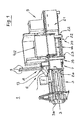
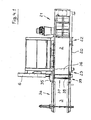
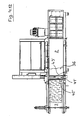
- the new baler is used for compacting loose material, such as preferably for pressing paper, cardboard, foils, expansive foams, styrofoam, hollow bodies, PET containers, metal buckets, barrels and the like packaging material.
- the FIG. 1 shows the new baler 1 in a perspective side view. It includes, among other things - seen in the representation from right to left in a horizontal orientation - a drive region 5, an adjoining press box 2, to which then a pressing channel 3 is connected. Above the press box 2 is a
- the new baler is arranged in the provided between the press box 2 and the press channel 3 transition section 2a.
- the Umschnürungsö the new baler is arranged. It consists of an arranged on the top band drawing station 8 and a corresponding thereto under the bottom of the baler 39 arranged Bandleitstation 7.
- the other components of the band drawing station 8 and the Bandleitstation 7 will be explained in more detail later.
- the stored in a tape supply station tape rolls are stored below the bottom of the baler.
- the tape storage station is provided sideways on the drive area in this new baler. From here, the tape is made by means of a first
- this area can be covered by a protective hood 19.
- a safety switch is provided so that when unauthorized opening of the press operation is interrupted.
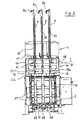
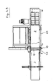
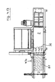
- the FIG. 2 is a cross section through the
- Transition portion 2a in the plane of movement of the tape drawing needles.
- the band drawing station 8 On the top of the baler 1, the band drawing station 8 is arranged. It consists of the two side parts 14 and a supported on these side parts 14 Traverse 13.
- corresponding through holes are provided through which the piston rods of the hydraulic cylinder 9, the pulling needles 10, during their downward or upward movement can pass through.
- head parts 11 At the free ends of the piston rods / pulling needles 10 head parts 11 are provided. These head parts have at their free end portions each have a fishing hook 12, the head part 11 and the fishing hook 12 may be one or more parts.
- a guide member 18 is provided between the side members 14.
- the length of the sliding surface 18a is such that until immersion of the head parts 11 in the respective leading vertical groove 38 of the pressing plate 13 selbige 11 is guided against rotation. From this position down to the lower position of the pulling needle securing against rotation of the fishing hook 12 is made by the relevant Vortikalnut 38. So that each pulling needle 10 can dive smoothly into the relevant vertical groove 38, an opening 15 is provided in the transition section 2a at the top of the baler 1 and a passage 17 in the bottom 39.
- a guide rod 24 Below the bottom 39 and below the bushings 17 is a guide rod 24, the below arranged Bandleitstation 7, which will be explained later in further details. Also visible is the second tape guide 23.
- ceramic sleeves are provided on the first tape guide 22, the second tape guide 23 and the guide rod 24 according to the intended number of Umschnürungsb skilledn. The ceramic sleeves serve to guide and deflect the respective band.
- each other two guide plates 16 are provided with which the Threading the head parts 11 is facilitated in the respective vertical groove 38.
- these guide straps 16 prevent the usually acute-angled ends of the head parts from being damaged when passing through the opening 15 arranged above the respective vertical groove.
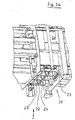
- FIG. 2a shows further details of the Bandleitstation 8.
- a through hole 11 b is provided in each head part 11.
- the through holes 11b of each head part 11 are aligned with each other.
- an optical sensor unit for example, a light barrier with a receiver and a transmitter is arranged.
- This light cabinet or its components are known in the art and therefore not shown here in the drawing. They are with respect to the position of the head parts 11 arranged so that only when all provided head parts 11 are in their home position and rest position, the transmitter receives a signal to the receiver and from this a sound signal is generated. Only when such a sound signal is present, the drive of the pressure plate is released, so that a pressing stroke can be performed.
- FIGS. 1 . 2 and 2a are known per se and for at least partially automatic operation of a baler necessary further known components, each a hydraulic motor, a controller for the hydraulics, a controller for the electrically driven parts of the baler and the electronic control unit not shown or not provided with a reference numeral Since these are provided in the usual number and with their usual function and therefore need not be further described here.
- FIG. 2 shows the tape drawing station 8 and its pulling needles 10 in a waiting position.
- the direction of movement is marked, in which the pulling needles 10 for detecting the Umschnürungsmaterials 20 move.
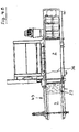
- a bale (see. Figure 4.9 ) is produced with a predetermined bale length or after reaching a number of predetermined pressing strokes of the punch remains 36 at the beginning of the press channel 3 in a front, the end position of a pressing stroke temporarily, so that still pressure is applied to the compressed into a bale waste material (see. Figure 4.9 ).
- the Umschnürungsmaterial is stored in a tape supply station 21, which, in this embodiment, the side of the drive portion 5 of the baler 1 is.
- a plastic strip 20 is used as Umschnürungmaterial, said plastic strip 20 has a flat, substantially rectangular cross section, but is not set to this cross section.
- the cross-section of the necking material may be round, elliptical, half-round or another cross-sectional shape.
- the free end 40 of a plastic strip 20 is withdrawn from the stored in the stripper station 21 tape reel and guided over a first tape guide 22 and a second tape guide 23 below and / or side of the bottom 39 of the baler 1 to a Bandleitstation 7 and fixed there, see , For this Figures 4.1 and 4.2 , This Bandleitstation 7 is part of the Tying unit 6; it will be described in detail later.
- the pulling needles 10 are lowered until their free ends have passed through the bottom 39 of the baling press 1 and are located below the plastic band 20.
- the front of a punch 36 arranged pressing plate 37 in its front, press channel side position.
- the vertical grooves 38 of the pressing plate 37 are below the pulling needles 10th
- a driver provided on each pulling needle captures the respective plastic band 20 and pulls the same upward, forming an open loop 41, until sections 42, 43 of the formed V-shaped loop 41 of plastic tape 20 above the press channel 3 and the press box 2 are.
- This position P corresponds approximately to the length of a pressed in the pressing channel 3 bale.
- the position P also defines the position of the front surface of a finished bale B.
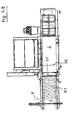
- clamping bodies 35 are provided in a corresponding number in the area of the passages for the Umschnürungsmaterial. In the positioning of the section 43, the clamping body 35 is "open” in one position and is closed after the positioning of said section 43.
- the first bale B 1 is then pressed until its front surface reaches the position P in the pressing channel 3.
- the portion, the length between this position P and the front of the press plate 37 is the length of a bale B.
- This length can be adjusted depending on the design of the baler or according to the material to be pressed material or mixture of waste by the operator of the baler or it is stored in the control unit of the baler 1 and is automatically retrieved while entering the type of material to be pressed waste at the control unit.
- the tape drawing needles 10 are returned from the tape drawing station 8 back to its original position moves, it is detected from each intended pulling needle 10, a plastic tape 20 and taken up, again to form a loop, which here has the reference numeral 41 ', with their sections 42' and 43 '. After reaching the upper position, the formed loop 41 'is separated in its inversion.
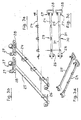
- a latching part 26 is fixed on one side of the bottom 39 in each case.
- the guide rod 24 and the mounting rod 25 have at one end a handle 28 and two upwardly directed tabs 27, the opposite end of the two components 24, 25 is free.
- FIG. 1 detachably fastened.
- one of the tabs 27 is placed on a bolt provided on the body of the baler and then set the held in the second tabs 27 threaded screw on the body.
- the guide rod 24 also has guide rings 29, through which the coming of the second tape guide 23 plastic tape 20 is passed to fix its end 40 to a notch 30 and holes 31 of the mounting rod 25. Between the guide rod 24 and the mounting rod 25 10 guide tabs 32 are arranged at the bottom 39 in the passageways for the pulling needles, with which the plastic strip 20 is guided in a position which facilitates the detection of selbigem by the free ends of the pulling needles 10.
Landscapes
- Engineering & Computer Science (AREA)
- Mechanical Engineering (AREA)
- Life Sciences & Earth Sciences (AREA)
- Environmental Sciences (AREA)
- Basic Packing Technique (AREA)
Priority Applications (2)
| Application Number | Priority Date | Filing Date | Title |
|---|---|---|---|
| EP12158101.1A EP2478757B1 (fr) | 2010-09-03 | 2010-09-03 | Presse à empaqueter |
| EP10009152A EP2425704A3 (fr) | 2010-09-03 | 2010-09-03 | Presse à paquet et procédé destiné à ceindre des paquets dans celle-ci |
Applications Claiming Priority (1)
| Application Number | Priority Date | Filing Date | Title |
|---|---|---|---|
| EP10009152A EP2425704A3 (fr) | 2010-09-03 | 2010-09-03 | Presse à paquet et procédé destiné à ceindre des paquets dans celle-ci |
Related Child Applications (1)
| Application Number | Title | Priority Date | Filing Date |
|---|---|---|---|
| EP12158101.1A Division EP2478757B1 (fr) | 2010-09-03 | 2010-09-03 | Presse à empaqueter |
Publications (2)
| Publication Number | Publication Date |
|---|---|
| EP2425704A2 true EP2425704A2 (fr) | 2012-03-07 |
| EP2425704A3 EP2425704A3 (fr) | 2012-03-14 |
Family
ID=44718996
Family Applications (2)
| Application Number | Title | Priority Date | Filing Date |
|---|---|---|---|
| EP10009152A Withdrawn EP2425704A3 (fr) | 2010-09-03 | 2010-09-03 | Presse à paquet et procédé destiné à ceindre des paquets dans celle-ci |
| EP12158101.1A Not-in-force EP2478757B1 (fr) | 2010-09-03 | 2010-09-03 | Presse à empaqueter |
Family Applications After (1)
| Application Number | Title | Priority Date | Filing Date |
|---|---|---|---|
| EP12158101.1A Not-in-force EP2478757B1 (fr) | 2010-09-03 | 2010-09-03 | Presse à empaqueter |
Country Status (1)
| Country | Link |
|---|---|
| EP (2) | EP2425704A3 (fr) |
Cited By (2)
| Publication number | Priority date | Publication date | Assignee | Title |
|---|---|---|---|---|
| JP2015536285A (ja) * | 2012-11-16 | 2015-12-21 | オハオリ エナジー,エス.エル. | 高精度結束機械及び結束プロセス |
| EP3323284A1 (fr) * | 2016-11-21 | 2018-05-23 | Bollegraaf Patents and Brands B.V. | Presse à balles et procédé de pressage et de nouage de balles dans une presse à balles |
Families Citing this family (1)
| Publication number | Priority date | Publication date | Assignee | Title |
|---|---|---|---|---|
| DE102022108056A1 (de) * | 2022-04-04 | 2023-10-05 | Unotech Gmbh | Kanalballenpresse mit Kreuzabbindung |
Citations (7)
| Publication number | Priority date | Publication date | Assignee | Title |
|---|---|---|---|---|
| DE2419151A1 (de) | 1974-04-20 | 1975-11-06 | Lindemann Maschfab Gmbh | Vorrichtung zum umschnueren von ballen |
| DE2504059A1 (de) | 1975-01-31 | 1976-08-05 | Lindemann Maschfab Gmbh | Herstellen verschnuerter ballen aus altmaterial |
| DE2540452A1 (de) | 1975-09-11 | 1977-03-17 | Lindemann Maschfab Gmbh | Verfahren und vorrichtung zum umschnueren von in einer kastenpresse hergestellten ballen aus mindestens vorwiegend nichtmetallischem stoff |
| DE2728203A1 (de) | 1977-06-23 | 1979-01-18 | Lindemann Maschfab Gmbh | Ballenpresse mit einem mehrere schnuernuten aufweisenden presstempel |
| DE3918065A1 (de) | 1989-06-02 | 1990-12-06 | Lindemann Maschfab Gmbh | Vorrichtung zum umschnueren von in einer ballenpresse hergestellten ballen |
| EP1190618B1 (fr) | 2000-09-23 | 2004-12-08 | Paal GmbH | Presse à balles pour matériau non-aggloméré |
| EP1785351A1 (fr) | 2005-11-09 | 2007-05-16 | Machinefabriek Bollegraaf Appingedam B.V. | Méthode, dispositif et enrouler pour attacher les extrémités d'un fil qui entoure une balle |
Family Cites Families (3)
| Publication number | Priority date | Publication date | Assignee | Title |
|---|---|---|---|---|
| DE2105163C3 (de) * | 1971-02-04 | 1974-02-28 | Paal's Packpressen-Fabrik Kg, 4500 Osnabrueck | Maschine zum Pressen und Umschnüren von Ballen mit Draht |
| DE2460464C3 (de) * | 1974-12-20 | 1981-11-26 | Lindemann Maschinenfabrik GmbH, 4000 Düsseldorf | Umschnürungsvorrichtung an einer Ballenpresse |
| DE3202233C2 (de) * | 1982-01-25 | 1987-05-14 | Lindemann Maschinenfabrik GmbH, 4000 Düsseldorf | Vorrichtung zum Umschnüren von Ballen |
-
2010
- 2010-09-03 EP EP10009152A patent/EP2425704A3/fr not_active Withdrawn
- 2010-09-03 EP EP12158101.1A patent/EP2478757B1/fr not_active Not-in-force
Patent Citations (7)
| Publication number | Priority date | Publication date | Assignee | Title |
|---|---|---|---|---|
| DE2419151A1 (de) | 1974-04-20 | 1975-11-06 | Lindemann Maschfab Gmbh | Vorrichtung zum umschnueren von ballen |
| DE2504059A1 (de) | 1975-01-31 | 1976-08-05 | Lindemann Maschfab Gmbh | Herstellen verschnuerter ballen aus altmaterial |
| DE2540452A1 (de) | 1975-09-11 | 1977-03-17 | Lindemann Maschfab Gmbh | Verfahren und vorrichtung zum umschnueren von in einer kastenpresse hergestellten ballen aus mindestens vorwiegend nichtmetallischem stoff |
| DE2728203A1 (de) | 1977-06-23 | 1979-01-18 | Lindemann Maschfab Gmbh | Ballenpresse mit einem mehrere schnuernuten aufweisenden presstempel |
| DE3918065A1 (de) | 1989-06-02 | 1990-12-06 | Lindemann Maschfab Gmbh | Vorrichtung zum umschnueren von in einer ballenpresse hergestellten ballen |
| EP1190618B1 (fr) | 2000-09-23 | 2004-12-08 | Paal GmbH | Presse à balles pour matériau non-aggloméré |
| EP1785351A1 (fr) | 2005-11-09 | 2007-05-16 | Machinefabriek Bollegraaf Appingedam B.V. | Méthode, dispositif et enrouler pour attacher les extrémités d'un fil qui entoure une balle |
Cited By (4)
| Publication number | Priority date | Publication date | Assignee | Title |
|---|---|---|---|---|
| JP2015536285A (ja) * | 2012-11-16 | 2015-12-21 | オハオリ エナジー,エス.エル. | 高精度結束機械及び結束プロセス |
| EP2921413A4 (fr) * | 2012-11-16 | 2016-07-27 | Hojaoli Energy S L | Machine à ficeler les ballots à haute précision et procédé de ficelage |
| EP3323284A1 (fr) * | 2016-11-21 | 2018-05-23 | Bollegraaf Patents and Brands B.V. | Presse à balles et procédé de pressage et de nouage de balles dans une presse à balles |
| US10654236B2 (en) | 2016-11-21 | 2020-05-19 | Bollegraaf Patents And Brands B.V. | Baling press and method of pressing and tying bales in a baling press |
Also Published As
| Publication number | Publication date |
|---|---|
| EP2478757B1 (fr) | 2017-11-08 |
| EP2425704A3 (fr) | 2012-03-14 |
| EP2478757A1 (fr) | 2012-07-25 |
Similar Documents
| Publication | Publication Date | Title |
|---|---|---|
| EP0084680B1 (fr) | Appareil pour lier des balles dans une presse à balles | |
| DE2709248C2 (de) | Verfahren und Vorrichtung zum Umschnüren von Ballen | |
| DE2656457C3 (de) | Ballenpresse | |
| EP3323603B1 (fr) | Presse à balle horizontale pourvue d'un dispositif de ficelage des ballots | |
| EP0084620B1 (fr) | Appareil pour cercler des balles | |
| CH466989A (de) | Verfahren zum Binden von Gegenständen sowie Bindemaschine zur Ausfürung des Verfahrens | |
| DE2728203C3 (de) | Ballenpresse mit einem mehrere Schnürnuten aufweisenden Preßstempel | |
| DE102022121422A1 (de) | Verfahren zum Verändern der Umreifung sowie Ballenpresse zur Anwendung dieses Verfahrens | |
| DE2460464A1 (de) | Vorrichtung zum umschnueren von ballen aus vorwiegend nichtmetallischem material | |
| DE102012008554A1 (de) | Kanalballenpresse | |
| EP2478757B1 (fr) | Presse à empaqueter | |
| DE102021112704A1 (de) | Verfahren zum Verändern der Umreifung sowie Ballenpresse zur Anwendung dieses Verfahrens | |
| DE102009040506B4 (de) | Ballenpresse | |
| DE102012202437A1 (de) | Presse zum Herstellen von Pressballen, Abbindeeinrichtung und Nachpresseinrichtung | |
| EP4261028B1 (fr) | Presse à balles à canal avec arrêt croisé | |
| EP2660160A2 (fr) | Presse à paquet à canal | |
| AT406454B (de) | Vorrichtung zum abbinden von mehreren, im wesentlichen übereinanderliegenden gegenständen | |
| EP0429798A1 (fr) | Grandes balles, en particulier de foin ou de paille | |
| DE202010017707U1 (de) | Ballenpresse | |
| EP0400380B1 (fr) | Appareil pour cercler des balles faites dans une presse à balles | |
| DE2552064B2 (de) | Verschnürungsvorrichtung für Ballenpressen | |
| EP3326451B1 (fr) | Presse à balles pour matière à presser en vrac | |
| DE10131165A1 (de) | Verfahren und Vorrichtung zum Abbinden eines Ballens in Ballenpressen | |
| EP3882166B1 (fr) | Procédé d'enfilage du brin de cerclage inférieur, et presse à balles destinée à l'utilisation dudit procédé | |
| EP1380506A2 (fr) | Appareil et procédé pour encercler des marchandises avec une bande de cerclage |
Legal Events
| Date | Code | Title | Description |
|---|---|---|---|
| PUAL | Search report despatched |
Free format text: ORIGINAL CODE: 0009013 |
|
| AK | Designated contracting states |
Kind code of ref document: A2 Designated state(s): AL AT BE BG CH CY CZ DE DK EE ES FI FR GB GR HR HU IE IS IT LI LT LU LV MC MK MT NL NO PL PT RO SE SI SK SM TR |
|
| AX | Request for extension of the european patent |
Extension state: BA ME RS |
|
| PUAI | Public reference made under article 153(3) epc to a published international application that has entered the european phase |
Free format text: ORIGINAL CODE: 0009012 |
|
| AK | Designated contracting states |
Kind code of ref document: A3 Designated state(s): AL AT BE BG CH CY CZ DE DK EE ES FI FR GB GR HR HU IE IS IT LI LT LU LV MC MK MT NL NO PL PT RO SE SI SK SM TR |
|
| AX | Request for extension of the european patent |
Extension state: BA ME RS |
|
| RIC1 | Information provided on ipc code assigned before grant |
Ipc: B65B 27/12 20060101ALI20120208BHEP Ipc: B30B 9/30 20060101ALI20120208BHEP Ipc: A01F 15/14 20060101AFI20120208BHEP |
|
| STAA | Information on the status of an ep patent application or granted ep patent |
Free format text: STATUS: THE APPLICATION IS DEEMED TO BE WITHDRAWN |
|
| 18D | Application deemed to be withdrawn |
Effective date: 20120915 |