EP0082906B1 - Dispositif d'accouplement pour la commande des cadres d'un métier à tisser - Google Patents
Dispositif d'accouplement pour la commande des cadres d'un métier à tisser Download PDFInfo
- Publication number
- EP0082906B1 EP0082906B1 EP81810517A EP81810517A EP0082906B1 EP 0082906 B1 EP0082906 B1 EP 0082906B1 EP 81810517 A EP81810517 A EP 81810517A EP 81810517 A EP81810517 A EP 81810517A EP 0082906 B1 EP0082906 B1 EP 0082906B1
- Authority
- EP
- European Patent Office
- Prior art keywords
- pawl
- lever
- shaft
- arrangement according
- coupling
- Prior art date
- Legal status (The legal status is an assumption and is not a legal conclusion. Google has not performed a legal analysis and makes no representation as to the accuracy of the status listed.)
- Expired
Links
Images
Classifications
-
- D—TEXTILES; PAPER
- D03—WEAVING
- D03C—SHEDDING MECHANISMS; PATTERN CARDS OR CHAINS; PUNCHING OF CARDS; DESIGNING PATTERNS
- D03C1/00—Dobbies
-
- D—TEXTILES; PAPER
- D03—WEAVING
- D03D—WOVEN FABRICS; METHODS OF WEAVING; LOOMS
- D03D51/00—Driving, starting, or stopping arrangements; Automatic stop motions
- D03D51/18—Automatic stop motions
- D03D51/44—Automatic stop motions acting on defective operation of loom mechanisms
- D03D51/46—Automatic stop motions acting on defective operation of loom mechanisms of shedding mechanisms
Definitions
- the invention relates to a coupling arrangement for controlling the shafts of a weaving machine, with an intermittently rotating drive shaft having at least one groove and a pawl which can be coupled into the groove and is arranged on an eccentric which is rotatably mounted on the drive shaft, and with a tab surrounding a crank rod for the eccentric Drive to the shafts.
- the invention is of particular importance if the coupling arrangement is controlled by electronic means and by an electronically stored binding program for the weaving machine.
- the invention has for its object to provide a coupling arrangement that takes these requirements into account.
- the invention is characterized by a scanning device arranged at least at one point within the gear connection from the drive shaft to the shaft, by means of which the function of the shafts is compared with the weaving program.
- a scanning device arranged at least at one point within the gear connection from the drive shaft to the shaft, by means of which the function of the shafts is compared with the weaving program.
- weft search device In the event of thread breakage and the resulting stopping of the weaving machine, it can be connected upstream by the so-called weft search device and the shafts can be moved back into a position by the electronic control system as a result of the monitoring device, which was present before the weft insertion fault. The weft entry can then be repeated.
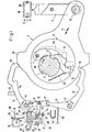
- a drive shaft 1 which is set in rotation by 180 "in each case from the main shaft of the weaving machine, contains two grooves 2 into which the nose 3 of a coupling pawl 5 pivotably mounted at 4 and acting under the action of a tension spring 60 can engage.
- the pawl 5 is on one Eccentric 6, which is rotatably mounted on shaft 1 and is enclosed by a tab 7. This is articulated at 8 to a transmission linkage 9, via which the back and forth movement of the tab 7 as shown in arrows 11 leads to an associated guide 95 guided in a guide Shaft 10 of a weaving machine is transmitted.
- the entire parts 1, 6, 7 form the so-called eccentric machine for driving and controlling all heald frames Weaving machine.
- the shafts are moved in a high or low position according to a binding program for the warp threads.
- a plate 23 is pivotally mounted at 22, which can be coupled with a reciprocating knife 25 moved back and forth according to arrow 24.
- the board 23 has a fork-shaped part 26 which forms a slot 27.
- the pin 28 of an arm 31 of a three-armed lifting element 31, 32, 33 engages in this.
- the lifting element can be moved up and down according to arrow 34 in FIG. 1.
- the arm 32 carries at 35, 36 pivotally mounted levers 41, 42, which form a slot 38 and are held together by a tension spring 37 which produces a so-called center spring, (overload lever) 41,42.
- the arm 32 of the lifting element carries a pin 44 which projects into the slot 38 between the levers 41, 42.
- a pin 45 protrudes into the slot 38, which is attached to a drive lever 48 which can be pivoted back and forth according to arrows 46 and 47.
- the lever 48 executes a full up and down stroke during operation, while the shaft 1 only rotates by 180 ° (double stroke method).
- the selection or program control device for engaging and disengaging the pawl 5 contains a fixed electromagnet 51 which is able to attract an armature 53 which can be pivoted by 52.
- the armature 53 works with the probe arm 33 of the lifting element 31 to 33.
- the control lever 14, 15 has a run-up edge 72 with which one arm 73 of a three-armed lever 73 to 75, which is pivotably mounted at 76, can cooperate.
- the arm 75 is under the action of a tension spring 77, which tends to pivot the lever 73 to 75 in the counterclockwise direction by 76.
- the bearing 76 is located on an arm 78 of a three-armed lever 78 to 80, which is pivotably mounted on the fixed bearing 81 and carries a stop 97 for the lever 73 to 75.
- the other end of the spring 77 is attached to its arm 79, which endeavors to pivot the lever 78 to 80 clockwise by 81.
- the arm 80 carries a sheet metal flag 82, which is able to cooperate with an inductive proximity switch 83. This is connected to the electronic control device by means of the connecting wires 84, from which the weaving or binding program for the movement of the shafts 10 is controlled.
- the arm 79 carries a roller 85 which can alternately snap into two catches 86, 87 which are located on an arm 88 of a two-armed locking lever 88, 89 which is pivoted at 90.
- the arm 89 is under the action of a tension spring 91, which tends to pivot the lever 88, 89 counterclockwise by 90.
- the tab 7 has a leading edge 92 with which the arm 80 of the shift lever 78 to 80 is able to cooperate.
- the mode of action is as follows. In the position according to FIG. 1, the drive shaft 1 is in one of its standstill positions, in which the pawl 5 can, if it is prescribed by the program, be coupled (into or out of the shaft 1).
- the shaft 10 is assumed to be in the down position. Furthermore, it is assumed that upon further rotation of the shaft 1 in accordance with arrow 66, the electromagnet 51 receives no current, so that the armature 53 blocks the upward movement of the arm 33 during the subsequent scanning process. Circuit board 23 remains in the cooperation area of the lifting knife 25.
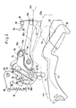
- the levers 14 to 18 are in the ineffective pivoting position shown in FIG. 1. In Fig. 2, this is the dot-dash line 14a.
- the electronic control device receives a signal via the lines 84, from which it can be seen that the shaft 10 is in the high position in the following standstill position of shaft 1. It also follows from the signal that the shaft remains engaged and if shaft 1 continues to rotate it will return to the low compartment.
- shaft 1 When the shaft 10 is in the high position, shaft 1, eccentric 6 and pawl 5 are pivoted by 180 ° with respect to the position according to FIG. 1, pawl 5 is also engaged.
- the tab 7 has been moved from its lowest position, shown in solid lines in FIG. 2, to a central position 7a, shown in broken lines.
- the shaft 1 then executes a further half rotation and the leading edge 92 moves from its central position 92a to the upper position 92b, which is indicated by the broken line in FIG.
- the arm 80 of the shift lever 78 to 80 is moved upward and the lever is pivoted by 81 in the counterclockwise direction, so that the position shown in FIG. 2 drawn out is reached again.
- Spring 77 is tensioned.
- Lever 73 to 75 initially still rests on arm 14 with the arm.
- Arm 14 is now moved back from position 14a to position 14 by lifting knife 25 and spring 55.
- Arm 73 follows him, so that lever 73-75 is pivoted counterclockwise by 76 ° and reaches the position shown in solid lines in FIG. 2, in which it rests on stop 97.
- the switching plate 82 likewise reaches the upper position shown in solid lines in FIG. 2, in which it is again in the area of cooperation with the proximity switch 83.
- the electronic control device receives a signal from the proximity switch 83, from which it can be seen that the coupled shaft 10 is on the way to the low position.
- the arm 80 and the switching flag 82 thus remain in the upper position shown in solid lines in the assumed working cycle. From a corresponding signal given in the electronic control device on the part of the proximity switch 83 it can be seen that the shaft 10 is now disengaged and remains disengaged until the parts 33, 53 again pivot the levers 14 to 18 and the pawl 5 is engaged again .
- the electronic control device is able to compare this process with the stored weaving or weaving program and, if it is correct, to cause the associated weaving machine not to be stopped but to continue to run. If the continuous back and forth movement of shaft 10 does not correspond to the binding program, the weaving machine is stopped.
- the switching flag 82 is always in front of the proximity switch 83.
- the corresponding signal for the electronic control device provides the Message that pawl 5 is disengaged and shaft 10 is stopped. Due to the disengagement position 5a of pawl 5, tab 7 also remains with its leading edge 92. Because of the latching parts 86 to 89, the switching flag 82 can only be lowered from its upper position again when the control levers 14 to 18 are pivoted out again due to the keying on the parts 33, 53 and the arm 14 reaches the position 14a.
- the respective shaft position and the direction of movement of the shaft 10 can optionally be tapped at another point of the shaft drive instead of on the control levers 14 to 18 and the tab 7, for. B. in the on the loom guide 95 for the shaft 10.
- another sensor for sensing the coupling process of the pawl 5 and / or the shaft movement process can be used, z. B. a photodiode or mechanical, hydraulic or pneumatic scanning elements, etc.
- Two scanning sensors 83 can also be used to scan the two positions 82, 82a.
Landscapes
- Engineering & Computer Science (AREA)
- Textile Engineering (AREA)
- Looms (AREA)
Claims (8)
Priority Applications (4)
| Application Number | Priority Date | Filing Date | Title |
|---|---|---|---|
| EP81810517A EP0082906B2 (fr) | 1981-12-28 | 1981-12-28 | Dispositif d'accouplement pour la commande des cadres d'un métier à tisser |
| DE8181810517T DE3172736D1 (en) | 1981-12-28 | 1981-12-28 | Coupling-system for operating the heald frames in a loom |
| US06/450,438 US4441528A (en) | 1981-12-28 | 1982-12-16 | Clutch arrangement for controlling the heddles of a weaving machine |
| JP57234927A JPS58115142A (ja) | 1981-12-28 | 1982-12-27 | 織機のヘルドを制御する連結装置 |
Applications Claiming Priority (1)
| Application Number | Priority Date | Filing Date | Title |
|---|---|---|---|
| EP81810517A EP0082906B2 (fr) | 1981-12-28 | 1981-12-28 | Dispositif d'accouplement pour la commande des cadres d'un métier à tisser |
Publications (3)
| Publication Number | Publication Date |
|---|---|
| EP0082906A1 EP0082906A1 (fr) | 1983-07-06 |
| EP0082906B1 true EP0082906B1 (fr) | 1985-10-23 |
| EP0082906B2 EP0082906B2 (fr) | 1989-04-12 |
Family
ID=8188689
Family Applications (1)
| Application Number | Title | Priority Date | Filing Date |
|---|---|---|---|
| EP81810517A Expired EP0082906B2 (fr) | 1981-12-28 | 1981-12-28 | Dispositif d'accouplement pour la commande des cadres d'un métier à tisser |
Country Status (4)
| Country | Link |
|---|---|
| US (1) | US4441528A (fr) |
| EP (1) | EP0082906B2 (fr) |
| JP (1) | JPS58115142A (fr) |
| DE (1) | DE3172736D1 (fr) |
Families Citing this family (11)
| Publication number | Priority date | Publication date | Assignee | Title |
|---|---|---|---|---|
| EP0109999B1 (fr) * | 1982-12-03 | 1988-03-09 | GebràDer Sulzer Aktiengesellschaft | Ratière pour métier à tisser |
| JPS6335847A (ja) * | 1986-07-24 | 1988-02-16 | 村田機械株式会社 | ドビ−機における綾落検出方法 |
| IT1246701B (it) * | 1990-07-11 | 1994-11-26 | Nuovopignone Ind Meccaniche Ef | Dispositivo di comando perfezionato per ratiere rotative ad altissima velocita' |
| US5139053A (en) * | 1991-01-04 | 1992-08-18 | Junichi Yokoi | Position detecting system for a harness frame in a weaving machine |
| IT1251107B (it) * | 1991-07-25 | 1995-05-04 | Costantino Vinciguerra | Perfezionamenti in una ratiera rotativa ad altissima velocita' |
| IT1252301B (it) * | 1991-11-15 | 1995-06-08 | Nuovo Pignone Spa | Sistema di controllo automatico per ratiera rotativa elettronica |
| IT1254219B (it) * | 1992-02-25 | 1995-09-14 | Eccentrico perfezionato per ratiera rotativa | |
| DE10127098C1 (de) * | 2001-06-02 | 2003-03-13 | Dornier Gmbh Lindauer | Vorrichtung zur Übertragung von Bewegungen und Kräften, insbesondere in Schaftwebmaschinen |
| ITMI20040086A1 (it) * | 2004-01-22 | 2004-04-22 | Fimtextile Spa | Sistema elettronico di controllo del disegno di tessuti in telai di tessitura a ratiera |
| US9687235B2 (en) | 2013-12-11 | 2017-06-27 | Innovative Trauma Care, Inc. | Double-row ratchet locking mechanism with single-bypass (‘arming’) functionality |
| RU2623613C1 (ru) * | 2016-06-17 | 2017-06-28 | Владимир Александрович Григорьев | Механизм передачи движения ремизке |
Family Cites Families (7)
| Publication number | Priority date | Publication date | Assignee | Title |
|---|---|---|---|---|
| US3568725A (en) * | 1969-08-08 | 1971-03-09 | Hindle Son & Co Ltd | Dobbies |
| US3998250A (en) * | 1976-05-03 | 1976-12-21 | Barber-Colman Company | Heddle transfer stop motion in a triaxial weaving machine |
| DE2741199C3 (de) * | 1977-07-21 | 1981-08-13 | Gebrüder Sulzer AG, 8401 Winterthur | Kupplung zum Steuern der Schäfte einer Webmaschine oder der Legeschiene einer Kettenwirkmaschine |
| DE3001310C2 (de) * | 1980-01-16 | 1982-02-04 | Maschinenfabrik Carl Zangs Ag, 4150 Krefeld | Rotations-Schaftmaschine |
| FR2478682A1 (fr) * | 1980-03-20 | 1981-09-25 | Staubli Sa Ets | Perfectionnements aux ratieres du type rotatif pour metiers a tisser |
| DE3069829D1 (en) * | 1980-09-12 | 1985-01-31 | Sulzer Ag | Coupling system for operating the heald frames in a loom |
| EP0049707B1 (fr) * | 1980-10-10 | 1984-04-04 | GebràDer Sulzer Aktiengesellschaft | Dispositif d'accouplement pour la commande des cadres d'un métier à tisser |
-
1981
- 1981-12-28 EP EP81810517A patent/EP0082906B2/fr not_active Expired
- 1981-12-28 DE DE8181810517T patent/DE3172736D1/de not_active Expired
-
1982
- 1982-12-16 US US06/450,438 patent/US4441528A/en not_active Expired - Fee Related
- 1982-12-27 JP JP57234927A patent/JPS58115142A/ja active Granted
Also Published As
| Publication number | Publication date |
|---|---|
| JPH0144811B2 (fr) | 1989-09-29 |
| JPS58115142A (ja) | 1983-07-08 |
| EP0082906B2 (fr) | 1989-04-12 |
| US4441528A (en) | 1984-04-10 |
| EP0082906A1 (fr) | 1983-07-06 |
| DE3172736D1 (en) | 1985-11-28 |
Similar Documents
| Publication | Publication Date | Title |
|---|---|---|
| EP0082906B1 (fr) | Dispositif d'accouplement pour la commande des cadres d'un métier à tisser | |
| DE2741199A1 (de) | Kupplung zur bewegung eines maschinenteils einer textilmaschine | |
| EP0047791B1 (fr) | Dispositif d'accouplement pour la commande des cadres d'un métier à tisser | |
| DE2741200A1 (de) | Kupplung zur bewegung eines maschinenteiles, insbesondere einer textilmaschine | |
| DE2904367B2 (de) | Elektromagnetischarbeitende Jacqard-Steuervorrichtung | |
| DE2222151C3 (de) | Vorrichtung zum Zurückweben bei schützenlosen Webmaschinen | |
| DE2942573A1 (de) | Rotationsschaftmaschine | |
| EP0048292B1 (fr) | Dispositif d'accouplement pour la commande des cadres d'un métier à tisser | |
| DE2935507A1 (de) | Verfharen und einrichtung zum beheben eines schussfadenbruches | |
| EP0129123B1 (fr) | Mécanique d'armure | |
| DE1805939A1 (de) | Schussfadensuchvorrichtung | |
| WO1986004365A1 (fr) | Procede pour la commande d'un metier a tisser et metier a tisser pour la mise en oeuvre du procede | |
| US4404993A (en) | Clutch arrangement for controlling a heddle of a weaving machine | |
| EP0050160A1 (fr) | Dispositif d'accouplement pour la commande des cadres d'un métier à tisser | |
| DE60309921T2 (de) | Vorrichtung zur durchführung der programmierung von drehbaren schaftmaschinen bei webmaschinen | |
| DE459184C (de) | Vorrichtung zum Schusssuchen fuer Schaftmaschinen | |
| DE3533329C2 (fr) | ||
| DE1154048B (de) | Fachbilde- oder Schuetzenkastenwechsel-vorrichtung | |
| EP0049707A1 (fr) | Dispositif d'accouplement pour la commande des cadres d'un métier à tisser | |
| DE667021C (de) | Schusssuchvorrichtung fuer Webstuehle | |
| DE3600857C2 (fr) | ||
| DE3837631C2 (fr) | ||
| EP0102515B1 (fr) | Machine à tisser à fausse navette avec un dispositif de recherche de la duite | |
| DE117572C (fr) | ||
| DE956210C (de) | Schaltgetriebe zum Einschalten des Litzenrahmenantriebes bei Rundwebmaschinen |
Legal Events
| Date | Code | Title | Description |
|---|---|---|---|
| PUAI | Public reference made under article 153(3) epc to a published international application that has entered the european phase |
Free format text: ORIGINAL CODE: 0009012 |
|
| 17P | Request for examination filed |
Effective date: 19811230 |
|
| AK | Designated contracting states |
Designated state(s): CH DE FR IT LI |
|
| RBV | Designated contracting states (corrected) |
Designated state(s): CH DE FR IT LI |
|
| ITF | It: translation for a ep patent filed |
Owner name: ING. ZINI MARANESI & C. S.R.L. |
|
| GRAA | (expected) grant |
Free format text: ORIGINAL CODE: 0009210 |
|
| AK | Designated contracting states |
Designated state(s): CH DE FR IT LI |
|
| REF | Corresponds to: |
Ref document number: 3172736 Country of ref document: DE Date of ref document: 19851128 |
|
| ET | Fr: translation filed | ||
| PLBI | Opposition filed |
Free format text: ORIGINAL CODE: 0009260 |
|
| 26 | Opposition filed |
Opponent name: W. SCHLAFHORST & CO. Effective date: 19860710 |
|
| ITF | It: translation for a ep patent filed |
Owner name: ING. ZINI MARANESI & C. S.R.L. |
|
| PUAH | Patent maintained in amended form |
Free format text: ORIGINAL CODE: 0009272 |
|
| STAA | Information on the status of an ep patent application or granted ep patent |
Free format text: STATUS: PATENT MAINTAINED AS AMENDED |
|
| 27A | Patent maintained in amended form |
Effective date: 19890412 |
|
| AK | Designated contracting states |
Kind code of ref document: B2 Designated state(s): CH DE FR IT LI |
|
| ET3 | Fr: translation filed ** decision concerning opposition | ||
| ITTA | It: last paid annual fee | ||
| PGFP | Annual fee paid to national office [announced via postgrant information from national office to epo] |
Ref country code: DE Payment date: 19941112 Year of fee payment: 14 |
|
| PGFP | Annual fee paid to national office [announced via postgrant information from national office to epo] |
Ref country code: FR Payment date: 19941115 Year of fee payment: 14 |
|
| PGFP | Annual fee paid to national office [announced via postgrant information from national office to epo] |
Ref country code: CH Payment date: 19941117 Year of fee payment: 14 |
|
| PG25 | Lapsed in a contracting state [announced via postgrant information from national office to epo] |
Ref country code: LI Effective date: 19951231 Ref country code: CH Effective date: 19951231 |
|
| REG | Reference to a national code |
Ref country code: CH Ref legal event code: PL |
|
| PG25 | Lapsed in a contracting state [announced via postgrant information from national office to epo] |
Ref country code: FR Effective date: 19960830 |
|
| PG25 | Lapsed in a contracting state [announced via postgrant information from national office to epo] |
Ref country code: DE Effective date: 19961001 |
|
| REG | Reference to a national code |
Ref country code: FR Ref legal event code: ST |
|
| REG | Reference to a national code |
Ref country code: CH Ref legal event code: AEN Free format text: AUFRECHTERHALTUNG DES PATENTES IN GEAENDERTER FORM |