EP0082906B1 - Coupling-system for operating the heald frames in a loom - Google Patents
Coupling-system for operating the heald frames in a loom Download PDFInfo
- Publication number
- EP0082906B1 EP0082906B1 EP81810517A EP81810517A EP0082906B1 EP 0082906 B1 EP0082906 B1 EP 0082906B1 EP 81810517 A EP81810517 A EP 81810517A EP 81810517 A EP81810517 A EP 81810517A EP 0082906 B1 EP0082906 B1 EP 0082906B1
- Authority
- EP
- European Patent Office
- Prior art keywords
- pawl
- lever
- shaft
- arrangement according
- coupling
- Prior art date
- Legal status (The legal status is an assumption and is not a legal conclusion. Google has not performed a legal analysis and makes no representation as to the accuracy of the status listed.)
- Expired
Links
Images
Classifications
-
- D—TEXTILES; PAPER
- D03—WEAVING
- D03C—SHEDDING MECHANISMS; PATTERN CARDS OR CHAINS; PUNCHING OF CARDS; DESIGNING PATTERNS
- D03C1/00—Dobbies
-
- D—TEXTILES; PAPER
- D03—WEAVING
- D03D—WOVEN FABRICS; METHODS OF WEAVING; LOOMS
- D03D51/00—Driving, starting, or stopping arrangements; Automatic stop motions
- D03D51/18—Automatic stop motions
- D03D51/44—Automatic stop motions acting on defective operation of loom mechanisms
- D03D51/46—Automatic stop motions acting on defective operation of loom mechanisms of shedding mechanisms
Definitions
- the invention relates to a coupling arrangement for controlling the shafts of a weaving machine, with an intermittently rotating drive shaft having at least one groove and a pawl which can be coupled into the groove and is arranged on an eccentric which is rotatably mounted on the drive shaft, and with a tab surrounding a crank rod for the eccentric Drive to the shafts.
- the invention is of particular importance if the coupling arrangement is controlled by electronic means and by an electronically stored binding program for the weaving machine.
- the invention has for its object to provide a coupling arrangement that takes these requirements into account.
- the invention is characterized by a scanning device arranged at least at one point within the gear connection from the drive shaft to the shaft, by means of which the function of the shafts is compared with the weaving program.
- a scanning device arranged at least at one point within the gear connection from the drive shaft to the shaft, by means of which the function of the shafts is compared with the weaving program.
- weft search device In the event of thread breakage and the resulting stopping of the weaving machine, it can be connected upstream by the so-called weft search device and the shafts can be moved back into a position by the electronic control system as a result of the monitoring device, which was present before the weft insertion fault. The weft entry can then be repeated.
- a drive shaft 1 which is set in rotation by 180 "in each case from the main shaft of the weaving machine, contains two grooves 2 into which the nose 3 of a coupling pawl 5 pivotably mounted at 4 and acting under the action of a tension spring 60 can engage.
- the pawl 5 is on one Eccentric 6, which is rotatably mounted on shaft 1 and is enclosed by a tab 7. This is articulated at 8 to a transmission linkage 9, via which the back and forth movement of the tab 7 as shown in arrows 11 leads to an associated guide 95 guided in a guide Shaft 10 of a weaving machine is transmitted.
- the entire parts 1, 6, 7 form the so-called eccentric machine for driving and controlling all heald frames Weaving machine.
- the shafts are moved in a high or low position according to a binding program for the warp threads.
- a plate 23 is pivotally mounted at 22, which can be coupled with a reciprocating knife 25 moved back and forth according to arrow 24.
- the board 23 has a fork-shaped part 26 which forms a slot 27.
- the pin 28 of an arm 31 of a three-armed lifting element 31, 32, 33 engages in this.
- the lifting element can be moved up and down according to arrow 34 in FIG. 1.
- the arm 32 carries at 35, 36 pivotally mounted levers 41, 42, which form a slot 38 and are held together by a tension spring 37 which produces a so-called center spring, (overload lever) 41,42.
- the arm 32 of the lifting element carries a pin 44 which projects into the slot 38 between the levers 41, 42.
- a pin 45 protrudes into the slot 38, which is attached to a drive lever 48 which can be pivoted back and forth according to arrows 46 and 47.
- the lever 48 executes a full up and down stroke during operation, while the shaft 1 only rotates by 180 ° (double stroke method).
- the selection or program control device for engaging and disengaging the pawl 5 contains a fixed electromagnet 51 which is able to attract an armature 53 which can be pivoted by 52.
- the armature 53 works with the probe arm 33 of the lifting element 31 to 33.
- the control lever 14, 15 has a run-up edge 72 with which one arm 73 of a three-armed lever 73 to 75, which is pivotably mounted at 76, can cooperate.
- the arm 75 is under the action of a tension spring 77, which tends to pivot the lever 73 to 75 in the counterclockwise direction by 76.
- the bearing 76 is located on an arm 78 of a three-armed lever 78 to 80, which is pivotably mounted on the fixed bearing 81 and carries a stop 97 for the lever 73 to 75.
- the other end of the spring 77 is attached to its arm 79, which endeavors to pivot the lever 78 to 80 clockwise by 81.
- the arm 80 carries a sheet metal flag 82, which is able to cooperate with an inductive proximity switch 83. This is connected to the electronic control device by means of the connecting wires 84, from which the weaving or binding program for the movement of the shafts 10 is controlled.
- the arm 79 carries a roller 85 which can alternately snap into two catches 86, 87 which are located on an arm 88 of a two-armed locking lever 88, 89 which is pivoted at 90.
- the arm 89 is under the action of a tension spring 91, which tends to pivot the lever 88, 89 counterclockwise by 90.
- the tab 7 has a leading edge 92 with which the arm 80 of the shift lever 78 to 80 is able to cooperate.
- the mode of action is as follows. In the position according to FIG. 1, the drive shaft 1 is in one of its standstill positions, in which the pawl 5 can, if it is prescribed by the program, be coupled (into or out of the shaft 1).
- the shaft 10 is assumed to be in the down position. Furthermore, it is assumed that upon further rotation of the shaft 1 in accordance with arrow 66, the electromagnet 51 receives no current, so that the armature 53 blocks the upward movement of the arm 33 during the subsequent scanning process. Circuit board 23 remains in the cooperation area of the lifting knife 25.
- the levers 14 to 18 are in the ineffective pivoting position shown in FIG. 1. In Fig. 2, this is the dot-dash line 14a.
- the electronic control device receives a signal via the lines 84, from which it can be seen that the shaft 10 is in the high position in the following standstill position of shaft 1. It also follows from the signal that the shaft remains engaged and if shaft 1 continues to rotate it will return to the low compartment.
- shaft 1 When the shaft 10 is in the high position, shaft 1, eccentric 6 and pawl 5 are pivoted by 180 ° with respect to the position according to FIG. 1, pawl 5 is also engaged.
- the tab 7 has been moved from its lowest position, shown in solid lines in FIG. 2, to a central position 7a, shown in broken lines.
- the shaft 1 then executes a further half rotation and the leading edge 92 moves from its central position 92a to the upper position 92b, which is indicated by the broken line in FIG.
- the arm 80 of the shift lever 78 to 80 is moved upward and the lever is pivoted by 81 in the counterclockwise direction, so that the position shown in FIG. 2 drawn out is reached again.
- Spring 77 is tensioned.
- Lever 73 to 75 initially still rests on arm 14 with the arm.
- Arm 14 is now moved back from position 14a to position 14 by lifting knife 25 and spring 55.
- Arm 73 follows him, so that lever 73-75 is pivoted counterclockwise by 76 ° and reaches the position shown in solid lines in FIG. 2, in which it rests on stop 97.
- the switching plate 82 likewise reaches the upper position shown in solid lines in FIG. 2, in which it is again in the area of cooperation with the proximity switch 83.
- the electronic control device receives a signal from the proximity switch 83, from which it can be seen that the coupled shaft 10 is on the way to the low position.
- the arm 80 and the switching flag 82 thus remain in the upper position shown in solid lines in the assumed working cycle. From a corresponding signal given in the electronic control device on the part of the proximity switch 83 it can be seen that the shaft 10 is now disengaged and remains disengaged until the parts 33, 53 again pivot the levers 14 to 18 and the pawl 5 is engaged again .
- the electronic control device is able to compare this process with the stored weaving or weaving program and, if it is correct, to cause the associated weaving machine not to be stopped but to continue to run. If the continuous back and forth movement of shaft 10 does not correspond to the binding program, the weaving machine is stopped.
- the switching flag 82 is always in front of the proximity switch 83.
- the corresponding signal for the electronic control device provides the Message that pawl 5 is disengaged and shaft 10 is stopped. Due to the disengagement position 5a of pawl 5, tab 7 also remains with its leading edge 92. Because of the latching parts 86 to 89, the switching flag 82 can only be lowered from its upper position again when the control levers 14 to 18 are pivoted out again due to the keying on the parts 33, 53 and the arm 14 reaches the position 14a.
- the respective shaft position and the direction of movement of the shaft 10 can optionally be tapped at another point of the shaft drive instead of on the control levers 14 to 18 and the tab 7, for. B. in the on the loom guide 95 for the shaft 10.
- another sensor for sensing the coupling process of the pawl 5 and / or the shaft movement process can be used, z. B. a photodiode or mechanical, hydraulic or pneumatic scanning elements, etc.
- Two scanning sensors 83 can also be used to scan the two positions 82, 82a.
Description
Die Erfindung betrifft eine Kupplungsanordnung zum Steuern der Schäfte einer Webmaschine, mit einer mindestens eine Nut aufweisenden, intermittierend drehenden Antriebswelle und einer in die Nut einkuppelbaren, auf einem auf der Antriebswelle drehbar gelagerten Exzenter angeordneten Klinke sowie mit einer den Exzenter umschließenden Lasche einer Kurbelstange für den Antrieb zu den Schäften.The invention relates to a coupling arrangement for controlling the shafts of a weaving machine, with an intermittently rotating drive shaft having at least one groove and a pawl which can be coupled into the groove and is arranged on an eccentric which is rotatably mounted on the drive shaft, and with a tab surrounding a crank rod for the eccentric Drive to the shafts.
Die Erfindung hat besondere Bedeutung, wenn die Kupplungsanordnung über elektronische Mittel und von einem elektronisch gespeicherten Bindungsprogramm für die Webmaschine gesteuert wird.The invention is of particular importance if the coupling arrangement is controlled by electronic means and by an electronically stored binding program for the weaving machine.
Bei einer bisherigen Kupplungsanordnung dieser Art (EP-A-0 047 791) wird die Funktion der Schäfte lediglich durch die Bedienungsperson der Webmaschine überwacht. Wenn die Webmaschine infolge einer Störung, z. B. wegen eines Schußfadenbruches, stillgesetzt wird, kann eine Schwierigkeit dadurch entstehen, daß die Webmaschine um mindestens ein Arbeitsspiel zurückgeschaltet werden muß, bevor der gestörte Schußeintrag wiederholt werden kann. Beim Zurückschalten gehen die Schäfte und die Steuereinrichtung aufgrund der besonderen Art der Kupplungsanordnung nicht selbsttätig in die vor der Störung innegehabte Position zurück. Vielmehr müssen Schäfte und elektronische Steuervorrichtung durch die Bedienungsperson einzeln zurückgeschaltet und ihre Stellung entsprechend dem Bindungsprogramm aufeinander abgestimmt werden, bevor der Schußeintrag wiederholt werden kann. Dies ist relativ kompliziert und erfordert von der Bedienungsperson besondere, technische Qualifikation.In a previous coupling arrangement of this type (EP-A-0 047 791), the function of the shafts is only monitored by the operator of the weaving machine. If the loom due to a malfunction, e.g. B. is stopped due to a weft break, a difficulty can arise from the fact that the weaving machine has to be switched back by at least one working cycle before the faulty weft entry can be repeated. When shifting down, the stems and the control device do not automatically return to the position they were in before the malfunction due to the special type of clutch arrangement. Rather, the shafts and the electronic control device must be individually switched back by the operator and their positions must be coordinated with one another in accordance with the binding program before the weft entry can be repeated. This is relatively complicated and requires special technical qualifications from the operator.
Der Erfindung liegt die Aufgabe zugrunde, eine diesen Anforderungen Rechnung tragende Kupplungsanordnung zu schaffen.The invention has for its object to provide a coupling arrangement that takes these requirements into account.
Die Erfindung ist gekennzeichnet durch eine an wenigstens einer Stelle innerhalb der getrieblichen Verbindung von Antriebswelle bis zum Schaft angeordnete Abtastvorrichtung, über welche die Funktion der Schäfte mit dem Webprogramm verglichen wird. Hierdurch läßt sich während des Webbetriebes die jeweilige Position der Schäfte (Hoch-, Tief- oder Mittelfachstellung) sowie gegebenenfalls die jeweilige Bewegungsrichtung der Schäfte selbsttätig kontrollieren. Bei etwaigem Abweichen vom Programm kann dann die Maschine noch vor dem Eintrag eines fehlerhaften Schusses stillgesetzt werden.The invention is characterized by a scanning device arranged at least at one point within the gear connection from the drive shaft to the shaft, by means of which the function of the shafts is compared with the weaving program. In this way, the respective position of the shafts (high, low or middle position) and, if necessary, the respective direction of movement of the shafts can be checked automatically during weaving operation. In the event of any deviations from the program, the machine can then be stopped before an incorrect shot is entered.
Bei Fadenbruch und der dadurch verursachten Stillsetzung der Webmaschine kann diese durch die sogenannte Schuß-Suchvorrichtung vorgeschaltet und die Schäfte können dabei von der elektronischen Steuerung aus infolge der Überwachungseinrichtung wieder in eine Position gerückt werden, die vor der Schußeintragsstörung vorhanden war. Der Schußeintrag kann alsdann wiederholt werden.In the event of thread breakage and the resulting stopping of the weaving machine, it can be connected upstream by the so-called weft search device and the shafts can be moved back into a position by the electronic control system as a result of the monitoring device, which was present before the weft insertion fault. The weft entry can then be repeated.
Weitere Merkmale ergeben sich aus der folgenden Beschreibung von Ausführungsbeispielen in Verbindung mit der Zeichnung und den Ansprüchen.
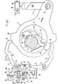
- Fig. 1 ist ein teilweise schematisierter Schnitt durch eine erfindungsgemäß ausgebildete Kupplungsanordnung zur Steuerung von Webschäften einer Webmaschine,
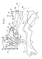
- Fig.2 veranschaulicht ein zugehöriges Detail in größerem Maßstab.
- 1 is a partially schematic section through a coupling arrangement designed according to the invention for controlling heald frames of a weaving machine,
- Fig. 2 illustrates an associated detail on a larger scale.
Eine von der Hauptwelle der Webmaschine aus absatzweise jeweils um 180" in Drehung versetzte Antriebswelle 1 enthält zwei Nuten 2, in welche die Nase 3 einer bei 4 schwenkbar gelagerten, unter Wirkung einer Zugfeder 60 stehenden Kupplungsklinke 5 eingreifen kann. Die Klinke 5 ist auf einem auf Welle 1 drehbar gelagerten Exzenter 6 gelagert, der von einer Lasche 7 umschlossen ist. Diese ist bei 8 an einem Übertragungsgestänge 9 angelenkt, über welches die gemäß Pfeilen 11 entstehende Hin- und Herbewegung der Lasche 7 auf einen zugehörigen, in einer Führung 95 geführten Schaft 10 einer Webmaschine übertragen wird.A
Auf Welle 1 sind eine ganze Anzahl, z. B. sechs bis zwölf der in Fig. 1 dargestellten Antriebsteile 6, 7 angeordnet, nämlich zu jedem Schaft der Webmaschine ein Exzenter 6 und eine Lasche 7. Die gesamten Teile 1, 6, 7 bilden die sogenannte Exzentermaschine für Antrieb und Steuerung sämtlicher Webschäfte der Webmaschine. Die Schäfte werden entsprechend einem Bindungsprogramm für die Kettfäden in Hoch- oder Tieffachstellung bewegt.On
Zur Betätigung der Klinke 5 während des Betriebes sind zwei auf den ortsfesten Lagerzapfen 12, 13 schwenkbar gelagerte Steuerhebel 14, 15 bzw. 16, 17 eingebaut, die an den freien Enden Haken 18 aufweisen, welche in den Weg der Klinke 5 verschwenkt werden können. Die beiden Steuerhebel sind mit den Armen 15, 17 bei 21 durch ein Gelenk verbunden.To operate the
Auf dem Arm 15 ist bei 22 eine Platine 23 schwenkbar gelagert, die mit einem gemäß Pfeil 24 hin- und herbewegten Hubmesser 25 gekuppelt werden kann.On the arm 15 a
Die Platine 23 besitzt einen gabelförmigen Teil 26, der einen Schlitz 27 bildet. In diesen greift der Zapfen 28 eines Armes 31 eines dreiarmigen Hubelementes 31, 32, 33 ein. Das Hubelement ist gemäß Pfeil 34 in Fig. 1 auf und ab beweglich. Der Arm 32 trägt bei 35, 36 schwenkbar gelagerte, durch eine eine sogenannte Mittelpunktsfederung erzeugende Zugfeder 37 zusammengehaltene, einen Schlitz 38 bildende Hebel (Überlastungshebel) 41,42. Der Arm 32 des Hubelementes trägt einen Zapfen 44, welcher in den Schlitz 38 zwischen den Hebeln 41, 42 ragt. Schließlich ragt in den Schlitz 38 noch ein Zapfen 45, der auf einem gemäß Pfeil 46 und 47 hin- und herverschwenkbaren Antriebshebel 48 angebracht ist. Der Hebel 48 führt während des Betriebes einen vollen Auf- und Abwärtshub aus, während die Welle 1 nur um 180° dreht (Doppelhub-Verfahren).The
Die Selektionier- oder Programmsteuereinrichtung für das Ein- und Auskuppeln der Klinke 5 enthält einen ortsfesten Elektromagneten 51, der einen um 52 schwenkbaren Anker 53 anzuziehen vermag. Der Anker 53 arbeitet mit dem Tastarm 33 des Hubelementes 31 bis 33 zusammen.The selection or program control device for engaging and disengaging the
Durch einen ortsfesten Anschlag 54 ist die Verschwenkbewegung der Steuerhebel 14 bis 17 begrenzt, da der Arm 17 auf den Anschlag unter Wirkung der Zugfeder 55 aufzuschlagen vermag.The pivoting movement of the control levers 14 to 17 is limited by a fixed
Der Steuerhebel 14, 15 besitzt eine Auflaufkante 72, mit welcher der eine Arm 73 eines dreiarmigen, bei 76 schwenkbar gelagerten Hebels 73 bis 75 kooperieren kann. Der Arm 75 steht unter der Wirkung einer Zugfeder 77, die bestrebt ist, den Hebel 73 bis 75 im Gegenzeigersinn um 76 zu verschwenken.The
Das Lager 76 befindet sich an einem Arm 78 eines dreiarmigen, an dem ortsfesten Lager 81 schwenkbar gelagerten Hebels 78 bis 80, der einen Anschlag 97 für den Hebel 73 bis 75 trägt. An seinem Arm 79 ist das andere Ende der Feder 77 angebracht, die dadurch bestrebt ist, den Hebel 78 bis 80 im Uhrzeigersinn um 81 zu verschwenken. Der Arm 80 trägt eine Blechfahne 82, die mit einem induktiven Näherungsschalter 83 zu kooperieren vermag. Dieser ist an die elektronische Steuereinrichtung mittels der Verbindungsdrähte 84 angeschlossen, von der aus das Web- bzw. Bindungsprogramm für die Bewegung der Schäfte 10 kontrolliert wird.The
Der Arm 79 trägt eine Rolle 85, die wechselweise in zwei Rasten 86, 87 einrasten kann, welche sich an einem Arm 88 eines zweiarmigen, bei 90 schwenkbar gelagerten Rasthebels 88, 89 befinden. Der Arm 89 steht unter der Wirkung einer Zugfeder 91, die bestrebt ist, den Hebel 88, 89 im Gegenzeigersinn um 90 zu verschwenken.The
Die Lasche 7 besitzt eine Auflaufkante 92, mit welcher der Arm 80 des Schalthebels 78 bis 80 zu kooperieren vermag.The tab 7 has a leading
Die Wirkungsweise ist folgende. Bei der Position nach Fig. 1 befindet sich die Antriebswelle 1 in einer ihrer Stillstandsstellungen, in der die Klinke 5, wenn es vom Programm her vorgeschrieben ist, gekuppelt (in die Welle 1 ein oder aus ihr ausgekuppelt) werden kann. Es ist angenommen, daß sich der Schaft 10 in Tieffachstellung befindet. Ferner ist angenommen, daß bei der weiteren Drehung der Welle 1 entsprechend Pfeil 66 der Elektromagnet 51 keinen Strom erhält, so daß der Anker 53 bei dem folgenden Tastvorgang die Aufwärtsbewegung des Armes 33 blockiert. Platine 23 bleibt im Kooperationsbereich des Hubmessers 25. Wenn dieses die in Fig. 1 dargestellte, rechte Extremstellung erreicht hat, sind die Hebel 14 bis 18 in der in Fig. 1 gezeichneten, wirkungslosen Ausschwenkstellung. In Fig. 2 ist dies die strichpunktiert gezeichnete Position 14a.The mode of action is as follows. In the position according to FIG. 1, the
Bei der Aufwärtsbewegung des Armes 14 in die Position 14a schlägt die Auflaufkante 72 auf den Arm 73, so daß der Hebel 73 bis 75 entgegen der Wirkung der Feder 77 in die in Fig. 2 strichpunktiert wiedergegebene Spannstellung gelangt. Dabei wird das nicht ortsfeste Lager 76 nach 76a überführt, wodurch der Schalthebel 78 bis 80 im Uhrzeigersinn um 81 verschwenkt wird und in die in Fig. 2 strichpunktiert dargestellte Ausschaltposition 78a bis 80a gelangt.During the upward movement of the
Bei dieser Verschwenkung schnappt eine an dem Arm 79 angebrachte Rolle 85 von der Rast 86 in die Rast 87, wobei der Schnapphebel 88, 89 vorübergehend im Uhrzeigersinn verschwenkt wird. Die Schaltfahne 82 befindet sich nunmehr in der strichpunktiert wiedergegebenen Position 82a, in der sie außerhalb des Kooperationsbereiches des Näherungsschalters 83 ist.During this pivoting, a
Die elektronische Steuervorrichtung erhält über die Leitungen 84 ein Signal, aus welchem hervorgeht, daß der Schaft 10 bei der folgenden Stillstandsposition von Welle 1 in Hochfachstellung ist. Auch ergibt sich aus dem Signal, daß der Schaft eingekuppelt bleibt und bei Weiterdrehung von Welle 1 wieder ins Tieffach gelangen wird. Bei der Hochfachstellung von Schaft 10 befinden sich Welle 1, Exzenter 6 und Klinke 5 um 180° verschwenkt gegenüber der Position nach Fig. 1, Klinke 5 ist ebenfalls eingekuppelt. Die Lasche 7 ist in der letzten Bewegungsphase von Welle 1 aus ihrer in Fig. 2 ausgezogen wiedergegebenen, untersten Position in eine mittlere, strichpunktiert wiedergegebene Position 7a bewegt worden.The electronic control device receives a signal via the
Anschließend führt die Welle 1 eine weitere Halbdrehung aus und es gelangt die Auflaufkante 92 aus ihrer mittleren Position 92a in die obere, in Fig.2 gestrichelt angedeutete Position 92b. Dabei wird der Arm 80 des Schalthebels 78 bis 80 aufwärtsbewegt und der Hebel im Gegenzeigersinn um 81 verschwenkt, so daß wieder die in Fig. 2 ausgezogen wiedergegebene Position erreicht ist. Dabei wird Feder 77 gespannt. Hebel 73 bis 75 liegt mit dem Arm zunächst weiterhin am Arm 14 an.The
Nunmehr wird Arm 14 durch das Hubmesser 25 und die Feder 55 aus der Position 14a in die Stellung 14 zurückbewegt. Dabei folgt ihm Arm 73, so daß Hebel 73-75 im Gegenzeigersinn um 76° verschwenkt wird und die in Fig. 2 ausgezogen dargestellte Stellung erreicht, in der er am Anschlag 97 anliegt. Ferner gelangt das Schaltblech 82 ebenfalls in die in Fig. 2 obere, ausgezeogen gezeichnete Position, in der es wieder im Kooperationsbereich mit dem Näherungsschalter 83 ist. Die elektronische Steuereinrichtung erhält vom Näherungsschalter 83 ein Signal, aus welchem hervorgeht, daß der eingekuppelte Schaft 10 auf dem Weg in die Tieffachposition ist.
Während der zuletzt erwähnten Halbdrehung von Welle 1 werden die Steuerhebel 14 bis 18 aufgrund der Kooperation von Platine 23 mit Hubmesser 25 in Fig. 1 einwärts verschwenkt, wodurch Arm 14 gemäß Fig.2 aus der oberen Stellung 14a wieder in die ausgezogene, untere Position gelangt.During the last-mentioned half-rotation of
Falls die Steuerhebel 14 bis 18 aufgrund der nächsten Abtastung mittels der Teile 33, 53 in dieser Einschwenkstellung verbleiben, läuft das Ende 61 der Klinke 5 auf das Ende 18 des Hebels 16, 17 auf, wodurch Klinke 5 in die in Fig. 1 gestrichelt angedeutete Auskupplungsstellung gelangt.If the control levers 14 to 18 remain in this pivoting position due to the next scanning by means of the
Damit verbleibt bei dem angenommenen Arbeitszyklus der Arm 80 und die Schaltfahne 82 in der in Fig. ausgezogen wiedergegebenen, oberen Position. Aus einem entsprechenden, in die elektronische Steuereinrichtung seitens des Näherungsschalters 83 gegebenen Signal geht hervor, daß der Schaft 10 nunmehr ausgekuppelt ist und so lange ausgekuppelt bleibt, bis wieder seitens der Teile 33,53 die Hebel 14 bis 18 ausgeschwenkt und Klinke 5 wieder eingekuppelt wird.The
Wie ersichtlich befinden sich bei ausgeschwenkten Steuerhebeln 14 bis 18 (strichpunktierte Position in Fig. 2) Klinke 5 und demzufolge Schaft 10 ständig in Bewegung. Dadurch wird auch die Lasche 7 mit ihrer Auflaufkante 92 ständig bewegt, so daß auch die Schaltfahne 82 in Fig. 2 ständig wechselweise vor den Näherungsschalter 83 bewegt und wieder von ihm entfernt wird.As can be seen, when the control levers 14 to 18 are pivoted out (dash-dotted position in FIG. 2), the
Die elektronische Steuereinrichtung vermag diesen Vorgang mit dem gespeicherten Web- bzw. Bindungsprogramm zu vergleichen und bei Richtigkeit zu veranlassen, daß die zugehörige Webmaschine nicht stillgesetzt wird, sondern weiterläuft. Sollte die dauernde Hin- und Herbewegung von Schaft 10 nicht dem Bindungsprogramm entsprechen, wird die Webmaschine stillgesetzt.The electronic control device is able to compare this process with the stored weaving or weaving program and, if it is correct, to cause the associated weaving machine not to be stopped but to continue to run. If the continuous back and forth movement of
Werden dagegen die Steuerhebel 14 bis 18 aufgrund der Abtastung seitens der Teile 33, 53 eingeschwenkt (ausgezogen wiedergegebene Position von Arm 14 in Fig. 2), so steht die Schaltfahne 82 ständig vor dem Näherungsschalter 83. Das entsprechende Signal für die elektronische Steuereinrichtung liefert die Nachricht, daß Klinke 5 ausgekuppelt und Schaft 10 stillgesetzt ist. Aufgrund der Auskupplungsposition 5a von Klinke 5 bleibt auch Lasche 7 mit ihrer Auflaufkante 92 stehen. Aufgrund der Rastteile 86 bis 89 vermag die Schaltfahne 82 erst dann wieder aus ihrer oberen Position abgesenkt zu werden, wenn wieder die Steuerhebel 14 bis 18 aufgrund der Tastung an den Teilen 33, 53 ausgeschwenkt werden und der Arm 14 in die Position 14a gelangt.If, on the other hand, the control levers 14 to 18 are pivoted in due to the scanning by the parts 33, 53 (extended position of
Die jeweilige Schaftposition und die Bewegungsrichtung des Schaftes 10 kann gegebenenfalls statt an den Steuerhebeln 14 bis 18 und der Lasche 7 auch an einer anderen Stelle des Schaftantriebes abgegriffen werden, z. B. in der an der Webmaschine befindlichen Führung 95 für den Schaft 10. Statt des Näherungsschalters 83 kann auch ein anderer Sensor zum Abtasten des Kupplungsvorganges der Klinke 5 und/oder des Schaftbewegungsvorganges verwendet werden, z. B. eine Fotodiode oder mechanische, hydraulische oder pneumatische Abtastorgane usw. Es können auch zwei Abtastsensoren 83 zum Abtasten der beiden Positionen 82, 82a benutzt werden.The respective shaft position and the direction of movement of the
Claims (8)
Priority Applications (4)
| Application Number | Priority Date | Filing Date | Title |
|---|---|---|---|
| DE8181810517T DE3172736D1 (en) | 1981-12-28 | 1981-12-28 | Coupling-system for operating the heald frames in a loom |
| EP81810517A EP0082906B2 (en) | 1981-12-28 | 1981-12-28 | Coupling-system for operating the heald frames in a loom |
| US06/450,438 US4441528A (en) | 1981-12-28 | 1982-12-16 | Clutch arrangement for controlling the heddles of a weaving machine |
| JP57234927A JPS58115142A (en) | 1981-12-28 | 1982-12-27 | Clutch apparatus for controlling shank of loom |
Applications Claiming Priority (1)
| Application Number | Priority Date | Filing Date | Title |
|---|---|---|---|
| EP81810517A EP0082906B2 (en) | 1981-12-28 | 1981-12-28 | Coupling-system for operating the heald frames in a loom |
Publications (3)
| Publication Number | Publication Date |
|---|---|
| EP0082906A1 EP0082906A1 (en) | 1983-07-06 |
| EP0082906B1 true EP0082906B1 (en) | 1985-10-23 |
| EP0082906B2 EP0082906B2 (en) | 1989-04-12 |
Family
ID=8188689
Family Applications (1)
| Application Number | Title | Priority Date | Filing Date |
|---|---|---|---|
| EP81810517A Expired EP0082906B2 (en) | 1981-12-28 | 1981-12-28 | Coupling-system for operating the heald frames in a loom |
Country Status (4)
| Country | Link |
|---|---|
| US (1) | US4441528A (en) |
| EP (1) | EP0082906B2 (en) |
| JP (1) | JPS58115142A (en) |
| DE (1) | DE3172736D1 (en) |
Families Citing this family (11)
| Publication number | Priority date | Publication date | Assignee | Title |
|---|---|---|---|---|
| EP0109999B1 (en) * | 1982-12-03 | 1988-03-09 | GebràDer Sulzer Aktiengesellschaft | Loom dobby |
| JPS6335847A (en) * | 1986-07-24 | 1988-02-16 | 村田機械株式会社 | Method for detecting lease falling for detecting lease falling in dobby machine |
| IT1246701B (en) * | 1990-07-11 | 1994-11-26 | Nuovopignone Ind Meccaniche Ef | IMPROVED CONTROL DEVICE FOR HIGH SPEED ROTARY DOBBIES |
| US5139053A (en) * | 1991-01-04 | 1992-08-18 | Junichi Yokoi | Position detecting system for a harness frame in a weaving machine |
| IT1251107B (en) * | 1991-07-25 | 1995-05-04 | Costantino Vinciguerra | REFINEMENTS IN A HIGH-SPEED ROTARY DOBBY |
| IT1252301B (en) * | 1991-11-15 | 1995-06-08 | Nuovo Pignone Spa | AUTOMATIC CONTROL SYSTEM FOR ELECTRONIC ROTARY DOBBY |
| IT1254219B (en) * | 1992-02-25 | 1995-09-14 | ECCENTRIC PERFECTED FOR ROTARY DOBBY | |
| DE10127098C1 (en) * | 2001-06-02 | 2003-03-13 | Dornier Gmbh Lindauer | Device for transmitting movements and forces, especially in dobby looms |
| ITMI20040086A1 (en) * | 2004-01-22 | 2004-04-22 | Fimtextile Spa | ELECTRONIC CONTROL SYSTEM FOR DRAWING OF FABRICS IN DOBBIN WEAVING FRAMES |
| CA2933406C (en) | 2013-12-11 | 2023-01-10 | Innovative Trauma Care, Inc. | Double-row ratchet locking mechanism with single-bypass ('arming') functionality |
| RU2623613C1 (en) * | 2016-06-17 | 2017-06-28 | Владимир Александрович Григорьев | Mechanism for driving heddle |
Family Cites Families (7)
| Publication number | Priority date | Publication date | Assignee | Title |
|---|---|---|---|---|
| US3568725A (en) * | 1969-08-08 | 1971-03-09 | Hindle Son & Co Ltd | Dobbies |
| US3998250A (en) * | 1976-05-03 | 1976-12-21 | Barber-Colman Company | Heddle transfer stop motion in a triaxial weaving machine |
| DE2741199C3 (en) * | 1977-07-21 | 1981-08-13 | Gebrüder Sulzer AG, 8401 Winterthur | Coupling for controlling the shafts of a weaving machine or the guide rail of a warp knitting machine |
| DE3001310C2 (en) * | 1980-01-16 | 1982-02-04 | Maschinenfabrik Carl Zangs Ag, 4150 Krefeld | Rotary dobby |
| FR2478682A1 (en) * | 1980-03-20 | 1981-09-25 | Staubli Sa Ets | IMPROVEMENTS IN RATIO OF THE ROTARY TYPE FOR WEAVING |
| DE3069829D1 (en) * | 1980-09-12 | 1985-01-31 | Sulzer Ag | Coupling system for operating the heald frames in a loom |
| EP0049707B1 (en) * | 1980-10-10 | 1984-04-04 | GebràDer Sulzer Aktiengesellschaft | Coupling system for operating the heald frames in a loom |
-
1981
- 1981-12-28 EP EP81810517A patent/EP0082906B2/en not_active Expired
- 1981-12-28 DE DE8181810517T patent/DE3172736D1/en not_active Expired
-
1982
- 1982-12-16 US US06/450,438 patent/US4441528A/en not_active Expired - Fee Related
- 1982-12-27 JP JP57234927A patent/JPS58115142A/en active Granted
Also Published As
| Publication number | Publication date |
|---|---|
| EP0082906A1 (en) | 1983-07-06 |
| JPH0144811B2 (en) | 1989-09-29 |
| JPS58115142A (en) | 1983-07-08 |
| US4441528A (en) | 1984-04-10 |
| EP0082906B2 (en) | 1989-04-12 |
| DE3172736D1 (en) | 1985-11-28 |
Similar Documents
| Publication | Publication Date | Title |
|---|---|---|
| EP0082906B1 (en) | Coupling-system for operating the heald frames in a loom | |
| DE2741199A1 (en) | CLUTCH FOR MOVING A MACHINE PART OF A TEXTILE MACHINE | |
| EP0047791B1 (en) | Coupling system for operating the heald frames in a loom | |
| DE2741200A1 (en) | CLUTCH FOR MOVING A MACHINE PART, IN PARTICULAR A TEXTILE MACHINE | |
| EP0109999A1 (en) | Loom dobby | |
| DE2904367B2 (en) | Electromagnetic Jacqard control device | |
| DE2222151C3 (en) | Device for backweaving in shuttleless looms | |
| DE2942573A1 (en) | ROTATION MACHINE | |
| EP0048292B1 (en) | Coupling arrangement for operating the heald shafts of a loom | |
| DE2935507A1 (en) | Weft-break rectification in rapier loom - with self-acting pick finder initiated automatically on break detection | |
| EP0129123B1 (en) | Loom dobby | |
| DE1805939A1 (en) | Weft search device | |
| WO1986004365A1 (en) | Method for the control of a weaving loom and weaving loom for implementing such method | |
| US4404993A (en) | Clutch arrangement for controlling a heddle of a weaving machine | |
| EP0050160A1 (en) | Coupling system for operating the heald frames in a loom | |
| DE60309921T2 (en) | DEVICE FOR IMPLEMENTING THE PROGRAMMING OF ROTATABLE SHAFTS IN WEB MACHINES | |
| DE459184C (en) | Device for searching for a shot for dobby machines | |
| DE3533329C2 (en) | ||
| DE1154048B (en) | Shed forming or contactor box changing device | |
| DE60310254T2 (en) | DEVICE FOR PROGRAMMING ROTATIONAL MACHINES FOR WEAVING MACHINES | |
| EP0049707A1 (en) | Coupling system for operating the heald frames in a loom | |
| DE667021C (en) | Weft search device for looms | |
| DE3600857C2 (en) | ||
| EP0080000A1 (en) | Coupling device to control the heald frames of a loom | |
| AT243199B (en) | Device for moving the heald frames on looms |
Legal Events
| Date | Code | Title | Description |
|---|---|---|---|
| PUAI | Public reference made under article 153(3) epc to a published international application that has entered the european phase |
Free format text: ORIGINAL CODE: 0009012 |
|
| 17P | Request for examination filed |
Effective date: 19811230 |
|
| AK | Designated contracting states |
Designated state(s): CH DE FR IT LI |
|
| RBV | Designated contracting states (corrected) |
Designated state(s): CH DE FR IT LI |
|
| ITF | It: translation for a ep patent filed |
Owner name: ING. ZINI MARANESI & C. S.R.L. |
|
| GRAA | (expected) grant |
Free format text: ORIGINAL CODE: 0009210 |
|
| AK | Designated contracting states |
Designated state(s): CH DE FR IT LI |
|
| REF | Corresponds to: |
Ref document number: 3172736 Country of ref document: DE Date of ref document: 19851128 |
|
| ET | Fr: translation filed | ||
| PLBI | Opposition filed |
Free format text: ORIGINAL CODE: 0009260 |
|
| 26 | Opposition filed |
Opponent name: W. SCHLAFHORST & CO. Effective date: 19860710 |
|
| ITF | It: translation for a ep patent filed |
Owner name: ING. ZINI MARANESI & C. S.R.L. |
|
| PUAH | Patent maintained in amended form |
Free format text: ORIGINAL CODE: 0009272 |
|
| STAA | Information on the status of an ep patent application or granted ep patent |
Free format text: STATUS: PATENT MAINTAINED AS AMENDED |
|
| 27A | Patent maintained in amended form |
Effective date: 19890412 |
|
| AK | Designated contracting states |
Kind code of ref document: B2 Designated state(s): CH DE FR IT LI |
|
| ET3 | Fr: translation filed ** decision concerning opposition | ||
| ITTA | It: last paid annual fee | ||
| PGFP | Annual fee paid to national office [announced via postgrant information from national office to epo] |
Ref country code: DE Payment date: 19941112 Year of fee payment: 14 |
|
| PGFP | Annual fee paid to national office [announced via postgrant information from national office to epo] |
Ref country code: FR Payment date: 19941115 Year of fee payment: 14 |
|
| PGFP | Annual fee paid to national office [announced via postgrant information from national office to epo] |
Ref country code: CH Payment date: 19941117 Year of fee payment: 14 |
|
| PG25 | Lapsed in a contracting state [announced via postgrant information from national office to epo] |
Ref country code: LI Effective date: 19951231 Ref country code: CH Effective date: 19951231 |
|
| REG | Reference to a national code |
Ref country code: CH Ref legal event code: PL |
|
| PG25 | Lapsed in a contracting state [announced via postgrant information from national office to epo] |
Ref country code: FR Effective date: 19960830 |
|
| PG25 | Lapsed in a contracting state [announced via postgrant information from national office to epo] |
Ref country code: DE Effective date: 19961001 |
|
| REG | Reference to a national code |
Ref country code: FR Ref legal event code: ST |
|
| REG | Reference to a national code |
Ref country code: CH Ref legal event code: AEN Free format text: AUFRECHTERHALTUNG DES PATENTES IN GEAENDERTER FORM |