EP0082764A1 - Kältekreislauf mit Motorkompressor, und Wärmepumpe versehen mit einem solchen Kreislauf - Google Patents
Kältekreislauf mit Motorkompressor, und Wärmepumpe versehen mit einem solchen Kreislauf Download PDFInfo
- Publication number
- EP0082764A1 EP0082764A1 EP82402289A EP82402289A EP0082764A1 EP 0082764 A1 EP0082764 A1 EP 0082764A1 EP 82402289 A EP82402289 A EP 82402289A EP 82402289 A EP82402289 A EP 82402289A EP 0082764 A1 EP0082764 A1 EP 0082764A1
- Authority
- EP
- European Patent Office
- Prior art keywords
- evaporator
- circuit
- compressor
- heat exchanger
- pump according
- Prior art date
- Legal status (The legal status is an assumption and is not a legal conclusion. Google has not performed a legal analysis and makes no representation as to the accuracy of the status listed.)
- Withdrawn
Links
Images

Classifications
-
- F—MECHANICAL ENGINEERING; LIGHTING; HEATING; WEAPONS; BLASTING
- F25—REFRIGERATION OR COOLING; COMBINED HEATING AND REFRIGERATION SYSTEMS; HEAT PUMP SYSTEMS; MANUFACTURE OR STORAGE OF ICE; LIQUEFACTION SOLIDIFICATION OF GASES
- F25B—REFRIGERATION MACHINES, PLANTS OR SYSTEMS; COMBINED HEATING AND REFRIGERATION SYSTEMS; HEAT PUMP SYSTEMS
- F25B29/00—Combined heating and refrigeration systems, e.g. operating alternately or simultaneously
- F25B29/003—Combined heating and refrigeration systems, e.g. operating alternately or simultaneously of the compression type system
-
- F—MECHANICAL ENGINEERING; LIGHTING; HEATING; WEAPONS; BLASTING
- F25—REFRIGERATION OR COOLING; COMBINED HEATING AND REFRIGERATION SYSTEMS; HEAT PUMP SYSTEMS; MANUFACTURE OR STORAGE OF ICE; LIQUEFACTION SOLIDIFICATION OF GASES
- F25B—REFRIGERATION MACHINES, PLANTS OR SYSTEMS; COMBINED HEATING AND REFRIGERATION SYSTEMS; HEAT PUMP SYSTEMS
- F25B43/00—Arrangements for separating or purifying gases or liquids; Arrangements for vaporising the residuum of liquid refrigerant, e.g. by heat
- F25B43/006—Accumulators
-
- F—MECHANICAL ENGINEERING; LIGHTING; HEATING; WEAPONS; BLASTING
- F25—REFRIGERATION OR COOLING; COMBINED HEATING AND REFRIGERATION SYSTEMS; HEAT PUMP SYSTEMS; MANUFACTURE OR STORAGE OF ICE; LIQUEFACTION SOLIDIFICATION OF GASES
- F25B—REFRIGERATION MACHINES, PLANTS OR SYSTEMS; COMBINED HEATING AND REFRIGERATION SYSTEMS; HEAT PUMP SYSTEMS
- F25B2341/00—Details of ejectors not being used as compression device; Details of flow restrictors or expansion valves
- F25B2341/001—Ejectors not being used as compression device
- F25B2341/0016—Ejectors for creating an oil recirculation
-
- F—MECHANICAL ENGINEERING; LIGHTING; HEATING; WEAPONS; BLASTING
- F25—REFRIGERATION OR COOLING; COMBINED HEATING AND REFRIGERATION SYSTEMS; HEAT PUMP SYSTEMS; MANUFACTURE OR STORAGE OF ICE; LIQUEFACTION SOLIDIFICATION OF GASES
- F25B—REFRIGERATION MACHINES, PLANTS OR SYSTEMS; COMBINED HEATING AND REFRIGERATION SYSTEMS; HEAT PUMP SYSTEMS
- F25B2400/00—General features or devices for refrigeration machines, plants or systems, combined heating and refrigeration systems or heat-pump systems, i.e. not limited to a particular subgroup of F25B
- F25B2400/07—Details of compressors or related parts
- F25B2400/071—Compressor mounted in a housing in which a condenser is integrated
Definitions
- the present invention relates to a refrigeration circuit with a compressor, and a heat pump provided with such a refrigeration circuit.
- Refrigerant circuits with a motor-compressor usually comprise in a closed circuit, mainly, a motor-compressor, a condenser and an evaporator.
- the structure and operation of wet type evaporator circuits are different from that of dry type evaporator circuits.
- the evaporator is directly and partially filled with refrigerant in the form of a liquid, and this liquid refrigerant evaporates there to give cold.
- a wet type evaporator refrigeration circuit generally comprises a large capacity evaporator with a large heat exchange surface, and a means which ensures the passage of the liquid refrigerant in the evaporator and the adjustment of the filling level of the latter in liquid refrigerant.
- This means is usually constituted by a valve of the float type for example.
- the evaporator is supplied with refrigerant in the form of mist or fine droplets.
- a dry-type evaporator refrigeration circuit frequently includes an anti-blow bottle placed between this evaporator and the motor-compressor.
- This anti-blow bottle although it increases the price of the circuit prevents the residual liquid refrigerant from entering directly into the motor-compressor and causing mechanical damage.
- the gaseous refrigerant discharged by the motor-compressor usually carries with it lubricant intended for the latter. This wandering lubricant is often trapped in the low pressure part of the circuit, especially in the downstream part of the evaporator and stays there.
- this refrigeration circuit is associated, through a heat exchanger, with a circuit of heat transfer liquid.
- the refrigeration circuit of the heat pump is in this case either organized in its arrangement in two parts, one remaining inside the premises mainly comprising a motor-compressor, a condenser and a heat exchanger and the other installed at the exterior of these premises mainly comprising an evaporator is organized in a compact arrangement, in a single block, suitable for being installed outside the premises.
- the refrigeration circuit of such a heat pump must have safety, resistance to mechanical and weathering characteristics, acoustics, efficiency, bulk, etc.
- the present invention makes it possible to produce an improved refrigeration circuit with an evaporator of the dry, economical type which has excellent characteristics in its application to a heat pump and in particular to that contributing to the heating of premises, and does not have the drawbacks mentioned in of the previous paragraphs.
- the invention also relates to the production of an economical, solid heat pump, effective in its contribution to space heating.
- the refrigerant circuit with a motor-compressor having in closed circuit mainly a condenser, an expansion valve, a dry-type evaporator, a suction manifold disposed between this evaporator and the motor-compressor, comprises in the interval between the regulator and the compressor, a connection pipe, a vertical composite suction manifold and an evaporator divided into several vertically spaced sections, mounted in parallel between this composite suction manifold and this pressure reducer, this vertical composite suction manifold also playing its role as an evaporator collector, the role of an anti-blow bottle and that of a pump-sprayer providing a return to the motor-compressor and without damage to the latter, lubricant and liquid refrigerant trapped in the circuit.
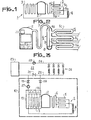
- a refrigeration circuit 1 produced according to the invention comprises in closed circuit mainly a motor-compressor 2, a condenser 3, a capillary 4 serving as an expansion valve and an evaporator of the dry type 5.
- the gaseous refrigerant is compressed by the motor-compressor 2, discharged into the condenser 3 where the refrigerant condenses in the form of liquid and gives off heat.
- This liquid refrigerant passes through a pressure reducer constituted by a capillary 4, expands in the form of mist or fine droplets in the evaporator 5 where it evaporates by absorbing heat in other words produces cold before returning to the motor-compressor 2 under the suction action of the latter. Practically the residual liquid refrigerant remaining in the evaporator 5 is insignificant or weak.
- the evaporator 5 is thus called the dry type evaporator.
- a vertical composite suction manifold 6 is mounted in this refrigeration circuit 1, between the motor-compressor 2 and the evaporator 5.
- the evaporator 5 is divided into several vertically spaced sections, mounted in parallel between the regulator 4 and the vertical composite manifold suction 6.
- the outlet ends of these sections lead respectively to different points of the height of this composite suction manifold 6.
- the number of these sections is greater than or equal to two.
- the evaporator 5 comprises three superimposed sections 5a, 5b, 5c mounted in parallel. The capacity of the evaporator and consequently that of its superimposed sections mounted in parallel are determined so that in the operation of the refrigeration circuit 1, the residual liquid refrigerant only fills one of these sections of the evaporator 5 as much as possible. , the lowest section 5a, and the lower part of the composite manifold 6.
- the vertical composite manifold 6 plays, in addition to its proper role as an intake manifold, the role of an anti-blow bottle and that of a sprayer-pump producing without damage to the compressor 2, the return to the latter of the lubricant and residual liquid refrigerant trapped in the circuit.
- the gaseous refrigerant expanded in the evaporator 5 borrows the vertical suction manifold 6 to return to the motor-compressor 2, through a connection pipe 7.
- the lubricant part of the compressor 2, driven by the coolant stream, and the residual liquid coolant tend, at the outlet of the evaporator 5, to separate from the gaseous coolant and fall down into the lower part 8 of the manifold vertical 6.
- the manifold 6 thus allows the gaseous refrigerant to get rid of the liquid refrigerant beforehand and to return alone in gaseous form to the motor compressor 2. Mechanical damage liable to be caused by a liquid penetrating into the compressor are thereby avoided.
- the vertical composite suction manifold 6 thus plays, apart from its proper role of suction manifold, also the role of an anti-blow bottle and advantageously replaces it.
- the vertical composite manifold 6 comprises on the one hand an elongated body 9 having a cross section larger than that of the connecting pipe 7, closed at its lower end 8, narrowed at its upper end 10 at the level of its connection to this connecting pipe 7 and in communication at several points on its side wall with the evaporator 5 and on the other hand within the enclosure of this body 9 and over almost the entire length of the latter, a capillary 11, the lower end of which is immersed in the mass of lubricant and liquid coolant trapped in the lower end 8 of the manifold 6 and the upper end disposed coaxially in the narrowed portion 10 of the upper end of this manifold.
- the narrowed part 10 of the upper end of the manifold 6 and the upper end of the capillary 11 create during the passage of the gaseous refrigerant called by the motor compressor 2, a venturi which sucks in lubricant and liquid refrigerant, trapped in the part 8 of the collector 6, pulverizes them and mixes them with the gaseous refrigerant stream returning to the compressor 2.
- This return of sprayed liquid refrigerant and lubricant does not damage the compressor 2 but also eliminates the defect or insufficient lubrication of the compressor encountered in the known refrigeration circuits.
- the refrigeration circuit 1 comprises a condenser 3 which form with an independent heat transfer fluid circuit 14, a heat exchanger 13 indicated by a rectangle in broken lines.
- the heat exchanger 13 is according to the invention preferably constituted by two separate coaxial circuits 3 and 14 of two different fluids, one of which is the hot compressed refrigerant discharged by the compressor 2 and the other is a heat transfer fluid consisting of l for example.
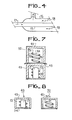
- the heat transfer fluid circuit 14 is constituted (FIG. 4) by a pipe 15 mounted coaxially in a pipe 16 forming the condenser 3.
- the pipe 15 in which the heat transfer fluid circulates is, in this exchanger 13, completely surrounded by hot compressed refrigerant evolving in the pipe 16 of the condenser 3.
- the heat exchange between these two fluids can thus be done in an efficient manner. This efficiency is enhanced when the stream 17 of heat transfer fluid and the stream of hot compressed refrigerant indicated by the arrows 18 are directed in opposite directions.
- the exchanger 13 then constitutes a counter-current exchanger.
- the heat transfer fluid circuit 14 is connected, through two valves 19 and 20, by its two ends to the inlet and to the outlet of a valve 21 of a space heating circuit. 22.
- the heating circuit 22 comprises, for example, a known heating plant 23 which sends heated heat transfer fluid, via supply pipes 24 and return pipes 25 to a network of radiators 26.
- the heat transfer fluid coming from the network of radiators 26 can pass through both the heat exchanger 13 of the heat pump 12 and the heating plant 23 to have a double intake of calories, before returning to the radiators 26.
- the heat pump 12 can provide heating only and when the heat pump 12 is at rest, the central unit 23 can also provide heating only.
- the circuit of the heat pump exchanger 13 can be isolated by closing the valves 19 and 20, the valve 21 then being open to allow the circuit to heating 22 to operate normally with the central 23.
- Circulators 27 and 28 can be mounted on the circuits of the exchanger 13 and heating 22 to accelerate the circulation of the heat transfer fluid.
- the heat pump 12 preferably comprises two modular elements 47, 48 either mountable in a two-part arrangement ( Figure 6) or assembled in a compact arrangement, in a single block ( Figure 5).
- the modular element 47 comprises the compressor 2 and the exchanger 13, mounted on a thermally insulating base 34 and hermetically closed by a thermally insulating bell 43.
- the exchanger 13 is preferably arranged around the compressor 2 and applied against its carcass. According to this structure, all the heat coming from the mechanical work of the motor-compressor 2 and from the compression of gaseous refrigerant is kept captive in the insulating enclosure defined by these base 34 and bell 43 to increase the potential for heat exchange with the fluid. coolant circulating in the heat exchanger 13.
- the modular element 48 comprises the evaporator 5 forming a perforated tubular wall, protected at its external lateral surface by a protective grid or fins 42, a fan 30 arranged in the upper part of the evaporator 5 to generate a current of air 31, 32 which passes through this evaporator so as to promote an intense heat exchange between the air and the refrigerant stream in the evaporator 5.
- the evaporator 5 is heated by the air stream 31, 32.
- the refrigerant current in the evaporator 5 draws heat from this air to evaporate.
- the air is moved laterally along the arrows 31 and discharged axially upwards according to the arrows 32 or in the opposite direction to these arrows 31 and 32.
- the fan 30 is protected by a grid 39 which closes the upper end of the evaporator 5.
- This evaporator 5 rests on a bottom plate 37.
- the modular elements 47 and 48 distant from each other and forming part of the same refrigeration circuit 1 are interconnected in a known manner by pipes not shown, intended for the circulation of the refrigerant.
- the heat transfer fluid circuit 14 of the exchanger 13 of the modular element 47 is also connected in a known manner to the space heating circuit 22 by pipes not shown.
- the modular element 48 is fixed on top of the modular element 47 (FIG. 5).
- the modular elements 47 and 48 are interconnected by pipes not shown in the common refrigeration circuit 1 while the heat transfer fluid circuit 14 of the heat exchanger 13 of the modular element 47 is connected to the heating circuit 22 by pipes not shown.
- connection of these pipes can be advantageously carried out with quick couplers of known type not shown.
- the runoff which, entering the modular element 48 collects on the bottom plate 37 of the latter is evacuated by means of grooves not shown, formed in the upper surface of this plate 37. These grooves are oriented so as to bring the run-off water either to the peripheral edge of the bottom plate 37 to evacuate it by spillage or to a passage hole 41 opening into a discharge pipe 46 formed in the thickness of the vertical wall of the insulating bell 43 of the modular element 47.
- the mechanical fixing connection between the modular elements 47 and 48 is obtained according to a known technique not described and with known fixing means not shown.
- the evaporator 5 is heated by a stream of liquid.
- This heating liquid can be river, borehole or natural water, recovered waste water, or a heating liquid forming part of a closed underground circuit.
- the evaporator 5 and the heating liquid circuit constitutes a heat exchanger 44 produced in a similar manner to that of the heat exchanger 13 with, for example, pipes similar to those shown in FIG. 4, mounted coaxially with one another. the other.
- the central pipe 51 intended for the circulation of the expanded refrigerant constitutes an evaporator circuit 51 while the external pipe 52, reserved for the flow of the heating liquid, constitutes a heating circuit 52.
- the heat pump 12 also comprises two modular elements 49, 50 which can be mounted in a two-part arrangement (FIG. 8) or which can be assembled in a compact arrangement, in a single block or in one piece (FIG. 7).
- the modular element 49 comprises a structure similar or preferably identical to that of the modular element 47 in FIGS. 5 and 6, namely the motor-compressor 2, the heat exchanger 13, the insulating base 34 and the insulating bell 43.
- the modular element 50 comprises a heat exchanger 44 mounted on a base plate 46 and protected by a bell 45.
- the protective bell 45 can have either an openwork and non-thermally insulating wall or a solid and thermally insulating wall.
- the protective cover 45 is formed from a solid and thermally insulating wall, only the heating fluid constitutes the heat source for the refrigerant.
- the protective cover 45 is perforated, the heat of the surrounding medium is added to the heating fluid to constitute the heat sources to the refrigerant of the evaporator 5 of the refrigeration circuit 1.
- Grooves not shown are also formed in the base plate 46 for discharging the runoff entering the modular element 50.
- the heat pump 12 thus constructed is solid and can resist mechanical and weathering attack while achieving excellent performance in its operation, and remaining economical in its manufacture by the simplicity of its structure.
Landscapes
- Engineering & Computer Science (AREA)
- Physics & Mathematics (AREA)
- Mechanical Engineering (AREA)
- Thermal Sciences (AREA)
- General Engineering & Computer Science (AREA)
- Chemical & Material Sciences (AREA)
- Analytical Chemistry (AREA)
- Power Engineering (AREA)
- Other Air-Conditioning Systems (AREA)
Applications Claiming Priority (2)
| Application Number | Priority Date | Filing Date | Title |
|---|---|---|---|
| FR8123738 | 1981-12-18 | ||
| FR8123738A FR2518720A1 (fr) | 1981-12-18 | 1981-12-18 | Circuit frigorifique a motocompresseurs, et pompe a chaleur munie d'un tel circuit |
Publications (1)
| Publication Number | Publication Date |
|---|---|
| EP0082764A1 true EP0082764A1 (de) | 1983-06-29 |
Family
ID=9265192
Family Applications (1)
| Application Number | Title | Priority Date | Filing Date |
|---|---|---|---|
| EP82402289A Withdrawn EP0082764A1 (de) | 1981-12-18 | 1982-12-14 | Kältekreislauf mit Motorkompressor, und Wärmepumpe versehen mit einem solchen Kreislauf |
Country Status (2)
| Country | Link |
|---|---|
| EP (1) | EP0082764A1 (de) |
| FR (1) | FR2518720A1 (de) |
Cited By (4)
| Publication number | Priority date | Publication date | Assignee | Title |
|---|---|---|---|---|
| FR2644357A1 (fr) * | 1989-03-14 | 1990-09-21 | Selnor Electromenager Nord | Separateur liquide-gaz et dispositif comportant un tel separateur |
| WO2013023630A3 (de) * | 2011-08-16 | 2013-05-23 | Ixetic Bad Homburg Gmbh | Kompaktes heiz-/kühl-modul und verwendung eines kompakten heiz-/kühl-moduls |
| WO2013113308A1 (de) * | 2012-02-02 | 2013-08-08 | Ixetic Bad Homburg Gmbh | Verdichter-wärmetauscher-einheit für ein heiz-kühl-modul für ein kraftfahrzeug |
| CN104236164A (zh) * | 2014-09-15 | 2014-12-24 | 美意(浙江)空调设备有限公司 | 一种超高温复叠式水源热泵系统 |
Families Citing this family (1)
| Publication number | Priority date | Publication date | Assignee | Title |
|---|---|---|---|---|
| CN109677236B (zh) * | 2018-12-26 | 2021-10-15 | 四川赛特制冷设备有限公司 | 电动车空调系统 |
Citations (20)
| Publication number | Priority date | Publication date | Assignee | Title |
|---|---|---|---|---|
| FR830861A (fr) * | 1936-12-17 | 1938-08-11 | Thomson Houston Comp Francaise | Perfectionnements aux systèmes réfrigérants |
| US2362698A (en) * | 1934-10-24 | 1944-11-14 | Gen Motors Corp | Refrigerating apparatus |
| US2516094A (en) * | 1949-05-17 | 1950-07-18 | V C Patterson & Associates Inc | Heat pump water heater |
| DE1102187B (de) * | 1957-03-05 | 1961-03-16 | Heat Pump & Refrigeration Ltd | Waermepumpenanlage |
| GB891573A (en) * | 1960-05-31 | 1962-03-14 | Heat Pump & Refrigeration Ltd | Improvements in or relating to heat pump systems |
| US3512374A (en) * | 1968-05-03 | 1970-05-19 | Parker Hannifin Corp | Suction accumulator for refrigeration systems |
| US3513663A (en) * | 1968-05-08 | 1970-05-26 | James B Martin Jr | Apparatus for heating and cooling liquids |
| FR2191089A1 (de) * | 1972-07-03 | 1974-02-01 | Ciat Sa | |
| FR2320511A1 (fr) * | 1975-08-05 | 1977-03-04 | Commissariat Energie Atomique | Perfectionnement aux pompes a chaleur |
| DE2604942A1 (de) * | 1976-02-09 | 1977-08-11 | Karl Dr Ing Schmidt | Waermepumpe |
| DE2624482A1 (de) * | 1976-06-01 | 1977-12-15 | Babcock Ag | Vorrichtung zum entfernen von unerwuenschten gasfoermigen bestandteilen aus einem abgas |
| US4138859A (en) * | 1977-11-02 | 1979-02-13 | General Electric Company | Split heat pump outdoor fan arrangement |
| DE2841711A1 (de) * | 1978-09-25 | 1980-04-03 | Dieter Dipl Ing Fleischer | Verdampfer fuer den betrieb mit ueberhitzungsregler |
| EP0009786A1 (de) * | 1978-10-02 | 1980-04-16 | Küppersbusch Aktiengesellschaft | Wärmepumpenheizungssystem |
| FR2455254A1 (fr) * | 1979-04-27 | 1980-11-21 | Bracht Armand | Pompe a chaleur |
| FR2475686A1 (fr) * | 1980-02-09 | 1981-08-14 | Viessmann Hans | Bati pour pompe a chaleur |
| FR2487056A1 (fr) * | 1980-07-18 | 1982-01-22 | Froid Ste Toulousaine | Procede permettant de refroidir ou de rechauffer un liquide contenu dans une citerne mobile et equipement destine a mettre en oeuvre un tel procede |
| US4320630A (en) * | 1980-11-06 | 1982-03-23 | Atlantic Richfield Company | Heat pump water heater |
| GB2092731A (en) * | 1981-02-10 | 1982-08-18 | Bosch Siemens Hausgeraete | Heat pump |
| DE3103362A1 (de) * | 1981-01-28 | 1982-08-19 | Harry 2351 Großenaspe Haase | Waermegewinnungsanlage nach dem prinzip der waermepumpe |
Family Cites Families (8)
| Publication number | Priority date | Publication date | Assignee | Title |
|---|---|---|---|---|
| CH135573A (de) * | 1928-06-16 | 1929-09-30 | Escher Wyss Maschf Ag | Verdampfer für Kälteerzeugungsanlagen, der ein oder mehrere Schlangenbündel aufweist. |
| US2042812A (en) * | 1934-02-23 | 1936-06-02 | Westinghouse Electric & Mfg Co | Refrigeration apparatus |
| US2700279A (en) * | 1952-06-12 | 1955-01-25 | Gen Motors Corp | Refrigerating apparatus and water heater |
| DE1051295B (de) * | 1957-02-16 | 1959-02-26 | Wilhelm Bock | Verfluessiger-Aggregat fuer Kaeltemaschinen |
| US3483714A (en) * | 1968-07-05 | 1969-12-16 | Virginia Chemicals Inc | Liquid trapping device |
| DE2452346A1 (de) * | 1974-11-05 | 1976-05-06 | Virginia Chemicals Inc | Fluessigkeitssaugspeicher |
| DE7601884U1 (de) * | 1976-01-21 | 1984-03-08 | Erich Schultze KG, 1000 Berlin | Fluessigkeitsabscheider mit absaugduese |
| DE2634482A1 (de) * | 1976-07-31 | 1978-02-02 | Goetzewerke | Waermepumpe |
-
1981
- 1981-12-18 FR FR8123738A patent/FR2518720A1/fr active Granted
-
1982
- 1982-12-14 EP EP82402289A patent/EP0082764A1/de not_active Withdrawn
Patent Citations (20)
| Publication number | Priority date | Publication date | Assignee | Title |
|---|---|---|---|---|
| US2362698A (en) * | 1934-10-24 | 1944-11-14 | Gen Motors Corp | Refrigerating apparatus |
| FR830861A (fr) * | 1936-12-17 | 1938-08-11 | Thomson Houston Comp Francaise | Perfectionnements aux systèmes réfrigérants |
| US2516094A (en) * | 1949-05-17 | 1950-07-18 | V C Patterson & Associates Inc | Heat pump water heater |
| DE1102187B (de) * | 1957-03-05 | 1961-03-16 | Heat Pump & Refrigeration Ltd | Waermepumpenanlage |
| GB891573A (en) * | 1960-05-31 | 1962-03-14 | Heat Pump & Refrigeration Ltd | Improvements in or relating to heat pump systems |
| US3512374A (en) * | 1968-05-03 | 1970-05-19 | Parker Hannifin Corp | Suction accumulator for refrigeration systems |
| US3513663A (en) * | 1968-05-08 | 1970-05-26 | James B Martin Jr | Apparatus for heating and cooling liquids |
| FR2191089A1 (de) * | 1972-07-03 | 1974-02-01 | Ciat Sa | |
| FR2320511A1 (fr) * | 1975-08-05 | 1977-03-04 | Commissariat Energie Atomique | Perfectionnement aux pompes a chaleur |
| DE2604942A1 (de) * | 1976-02-09 | 1977-08-11 | Karl Dr Ing Schmidt | Waermepumpe |
| DE2624482A1 (de) * | 1976-06-01 | 1977-12-15 | Babcock Ag | Vorrichtung zum entfernen von unerwuenschten gasfoermigen bestandteilen aus einem abgas |
| US4138859A (en) * | 1977-11-02 | 1979-02-13 | General Electric Company | Split heat pump outdoor fan arrangement |
| DE2841711A1 (de) * | 1978-09-25 | 1980-04-03 | Dieter Dipl Ing Fleischer | Verdampfer fuer den betrieb mit ueberhitzungsregler |
| EP0009786A1 (de) * | 1978-10-02 | 1980-04-16 | Küppersbusch Aktiengesellschaft | Wärmepumpenheizungssystem |
| FR2455254A1 (fr) * | 1979-04-27 | 1980-11-21 | Bracht Armand | Pompe a chaleur |
| FR2475686A1 (fr) * | 1980-02-09 | 1981-08-14 | Viessmann Hans | Bati pour pompe a chaleur |
| FR2487056A1 (fr) * | 1980-07-18 | 1982-01-22 | Froid Ste Toulousaine | Procede permettant de refroidir ou de rechauffer un liquide contenu dans une citerne mobile et equipement destine a mettre en oeuvre un tel procede |
| US4320630A (en) * | 1980-11-06 | 1982-03-23 | Atlantic Richfield Company | Heat pump water heater |
| DE3103362A1 (de) * | 1981-01-28 | 1982-08-19 | Harry 2351 Großenaspe Haase | Waermegewinnungsanlage nach dem prinzip der waermepumpe |
| GB2092731A (en) * | 1981-02-10 | 1982-08-18 | Bosch Siemens Hausgeraete | Heat pump |
Cited By (5)
| Publication number | Priority date | Publication date | Assignee | Title |
|---|---|---|---|---|
| FR2644357A1 (fr) * | 1989-03-14 | 1990-09-21 | Selnor Electromenager Nord | Separateur liquide-gaz et dispositif comportant un tel separateur |
| WO2013023630A3 (de) * | 2011-08-16 | 2013-05-23 | Ixetic Bad Homburg Gmbh | Kompaktes heiz-/kühl-modul und verwendung eines kompakten heiz-/kühl-moduls |
| WO2013113308A1 (de) * | 2012-02-02 | 2013-08-08 | Ixetic Bad Homburg Gmbh | Verdichter-wärmetauscher-einheit für ein heiz-kühl-modul für ein kraftfahrzeug |
| US9551516B2 (en) | 2012-02-02 | 2017-01-24 | Magna Powertrain Bad Homburg GmbH | Compressor-heat exchanger unit for a heating-cooling module for a motor vehicle |
| CN104236164A (zh) * | 2014-09-15 | 2014-12-24 | 美意(浙江)空调设备有限公司 | 一种超高温复叠式水源热泵系统 |
Also Published As
| Publication number | Publication date |
|---|---|
| FR2518720B1 (de) | 1984-09-14 |
| FR2518720A1 (fr) | 1983-06-24 |
Similar Documents
| Publication | Publication Date | Title |
|---|---|---|
| EP0046716B1 (de) | Kühlvorrichtung mit einer strahlenden Platte und einer Verdampferplatte | |
| EP0774102B1 (de) | Verflüssiger mit einbezogenem behälter für klimaanlage eines kraftfahrzeuges | |
| FR2765956A1 (fr) | Condenseur refrigerant incluant une partie de super-refroidissement | |
| EP2633245B1 (de) | Wärmeaustauschsystem zwischen zuluft und abluft und verfahren mit einem solchen system | |
| EP0010118A1 (de) | Wärmeaustauscher, insbesondere für atmosphärische Kühler | |
| EP0082764A1 (de) | Kältekreislauf mit Motorkompressor, und Wärmepumpe versehen mit einem solchen Kreislauf | |
| FR2465979A1 (fr) | Condenseur a caracteristiques de transfert de chaleur | |
| FR2724220A1 (fr) | Refrigerant atmospherique humide a dispositif antigel | |
| EP0320379B1 (de) | Absorptionsklimaanlage | |
| FR2505999A1 (fr) | Procede et appareil de condensation de vapeur pour extraire de facon continue un condensat a partir d'un courant de gaz comprime | |
| FR2548769A1 (fr) | Installation de chauffage a pompes a chaleur et a capteurs d'energie atmospherique | |
| EP0187571B1 (de) | Wärmeenergiekollektor und mit solchem Kollektor versehene Vorrichtung | |
| CH635669A5 (fr) | Machine pour la fabrication de glacons. | |
| EP0229410A1 (de) | Kältemaschine | |
| CA1087409A (fr) | Systeme d'echange thermique a fluide frigorigene | |
| CH649370A5 (fr) | Pompe a chaleur. | |
| FR2850122A1 (fr) | Dispositif d'extraction de l'eau presente dans l'air par condensation | |
| FR2524126A1 (fr) | Dispositif de stockage de chaleur et source froide pour pompe a chaleur comportant un tel dispositif | |
| FR2792965A1 (fr) | Equipement d'echange thermique pour vehicule automobile | |
| LU86935A1 (fr) | Procede pour la conservation de fleurs et/ou de plantes disposees dans un local et dispositif utilise pour ce procede | |
| FR2706531A1 (fr) | Vase d'expansion pour circuit de refroidissement de moteur thermique. | |
| FR2570172A1 (fr) | Echangeur perfectionne a tubes multiples | |
| FR2672114A1 (fr) | Unites de refrigeration pour enceintes refrigerees et installation de refrigeration utilisant de telles unites. | |
| FR2721697A1 (fr) | Chariot pour meuble réfrigéré. | |
| FR2677113A1 (fr) | Echangeur de chaleur tubulaire a ailettes pour rechauffer un fluide liquide par des gaz chauds. |
Legal Events
| Date | Code | Title | Description |
|---|---|---|---|
| PUAI | Public reference made under article 153(3) epc to a published international application that has entered the european phase |
Free format text: ORIGINAL CODE: 0009012 |
|
| AK | Designated contracting states |
Designated state(s): AT BE DE FR GB IT NL |
|
| 17P | Request for examination filed |
Effective date: 19831117 |
|
| STAA | Information on the status of an ep patent application or granted ep patent |
Free format text: STATUS: THE APPLICATION IS DEEMED TO BE WITHDRAWN |
|
| 18D | Application deemed to be withdrawn |
Effective date: 19850623 |
|
| RIN1 | Information on inventor provided before grant (corrected) |
Inventor name: BIANIC, CHRISTIAN |