EP0082764A1 - Refrigeration circuit with motor compressor, and heat pump provided with such a circuit - Google Patents
Refrigeration circuit with motor compressor, and heat pump provided with such a circuit Download PDFInfo
- Publication number
- EP0082764A1 EP0082764A1 EP82402289A EP82402289A EP0082764A1 EP 0082764 A1 EP0082764 A1 EP 0082764A1 EP 82402289 A EP82402289 A EP 82402289A EP 82402289 A EP82402289 A EP 82402289A EP 0082764 A1 EP0082764 A1 EP 0082764A1
- Authority
- EP
- European Patent Office
- Prior art keywords
- evaporator
- circuit
- compressor
- heat exchanger
- pump according
- Prior art date
- Legal status (The legal status is an assumption and is not a legal conclusion. Google has not performed a legal analysis and makes no representation as to the accuracy of the status listed.)
- Withdrawn
Links
Images

Classifications
-
- F—MECHANICAL ENGINEERING; LIGHTING; HEATING; WEAPONS; BLASTING
- F25—REFRIGERATION OR COOLING; COMBINED HEATING AND REFRIGERATION SYSTEMS; HEAT PUMP SYSTEMS; MANUFACTURE OR STORAGE OF ICE; LIQUEFACTION SOLIDIFICATION OF GASES
- F25B—REFRIGERATION MACHINES, PLANTS OR SYSTEMS; COMBINED HEATING AND REFRIGERATION SYSTEMS; HEAT PUMP SYSTEMS
- F25B29/00—Combined heating and refrigeration systems, e.g. operating alternately or simultaneously
- F25B29/003—Combined heating and refrigeration systems, e.g. operating alternately or simultaneously of the compression type system
-
- F—MECHANICAL ENGINEERING; LIGHTING; HEATING; WEAPONS; BLASTING
- F25—REFRIGERATION OR COOLING; COMBINED HEATING AND REFRIGERATION SYSTEMS; HEAT PUMP SYSTEMS; MANUFACTURE OR STORAGE OF ICE; LIQUEFACTION SOLIDIFICATION OF GASES
- F25B—REFRIGERATION MACHINES, PLANTS OR SYSTEMS; COMBINED HEATING AND REFRIGERATION SYSTEMS; HEAT PUMP SYSTEMS
- F25B43/00—Arrangements for separating or purifying gases or liquids; Arrangements for vaporising the residuum of liquid refrigerant, e.g. by heat
- F25B43/006—Accumulators
-
- F—MECHANICAL ENGINEERING; LIGHTING; HEATING; WEAPONS; BLASTING
- F25—REFRIGERATION OR COOLING; COMBINED HEATING AND REFRIGERATION SYSTEMS; HEAT PUMP SYSTEMS; MANUFACTURE OR STORAGE OF ICE; LIQUEFACTION SOLIDIFICATION OF GASES
- F25B—REFRIGERATION MACHINES, PLANTS OR SYSTEMS; COMBINED HEATING AND REFRIGERATION SYSTEMS; HEAT PUMP SYSTEMS
- F25B2341/00—Details of ejectors not being used as compression device; Details of flow restrictors or expansion valves
- F25B2341/001—Ejectors not being used as compression device
- F25B2341/0016—Ejectors for creating an oil recirculation
-
- F—MECHANICAL ENGINEERING; LIGHTING; HEATING; WEAPONS; BLASTING
- F25—REFRIGERATION OR COOLING; COMBINED HEATING AND REFRIGERATION SYSTEMS; HEAT PUMP SYSTEMS; MANUFACTURE OR STORAGE OF ICE; LIQUEFACTION SOLIDIFICATION OF GASES
- F25B—REFRIGERATION MACHINES, PLANTS OR SYSTEMS; COMBINED HEATING AND REFRIGERATION SYSTEMS; HEAT PUMP SYSTEMS
- F25B2400/00—General features or devices for refrigeration machines, plants or systems, combined heating and refrigeration systems or heat-pump systems, i.e. not limited to a particular subgroup of F25B
- F25B2400/07—Details of compressors or related parts
- F25B2400/071—Compressor mounted in a housing in which a condenser is integrated
Abstract
Description
La présente invention concerne un circuit frigorifique à motocompresseur, et une pompe à chaleur munie d'un tel circuit frigorifique.The present invention relates to a refrigeration circuit with a compressor, and a heat pump provided with such a refrigeration circuit.
Les circuits frigorifiques à motocompresseur comprennent habituellement en circuit fermé, principalement, un motocompresseur, un condenseur et un évaporateur. Cependant dans ces circuits frigorifiques à motocompresseur on distingue ceux qui ont un évaporateur du type humide et ceux qui sont pourvus d'un évaporateur du type à sec. La structure et le fonctionnement des circuits à évaporateur du type humide sont différents de ceux des circuits à évaporateur du type à sec. Dans un circuit frigorifique à évaporateur du type humide, l'évaporateur est directement et partiellement rempli de réfrigérant sous forme de liquide, et ce réfrigérant liquide s'y évapore pour donner du froid. En plus de la température du milieu environnant, la vitesse d'évaporation du réfrigérant liquide dans cet évaporateur de type humide dépend en particulier de l'importance de la surface développée par cet évaporateur. Ainsi un circuit frigorifique à évaporateur du type humide comprend généralement un évaporateur à grande capacité et à grande surface d'échange thermique, et un moyen qui assure le passage du réfrigérant liquide dans l'évaporateur et le réglage du niveau de remplissage de ce dernier en réfrigérant liquide. Ce moyen est habituellement constitué par un robinet du type à flotteur par exemple. Dans un circuit frigorifique à évaporateur du type à sec, l'évaporateur est alimenté en réfrigérant sous forme de brouillard ou fines gouttelettes. Ce réfrigérant sous forme de brouillard entrant en contact avec la paroi de l'évaporateur s'évapore rapidement et produit du froid. Il en résulte que dans un circuit frigorifique à évaporateur du type à sec, l'évaporateur a habituellement une capacité et une surface d'échange thermique relativement moyennes, et que le réfrigérant résiduel sous forme de liquide qui se trouve dans cet évaporateur est généralement en quantité insignifiante ou faible.Refrigerant circuits with a motor-compressor usually comprise in a closed circuit, mainly, a motor-compressor, a condenser and an evaporator. However, in these refrigeration circuits with a compressor, a distinction is made between those which have a wet type evaporator and those which are provided with a dry type evaporator. The structure and operation of wet type evaporator circuits are different from that of dry type evaporator circuits. In a wet type evaporator refrigeration circuit, the evaporator is directly and partially filled with refrigerant in the form of a liquid, and this liquid refrigerant evaporates there to give cold. In addition to the temperature of the surrounding medium, the rate of evaporation of the liquid refrigerant in this wet type evaporator depends in particular on the size of the surface developed by this evaporator. Thus, a wet type evaporator refrigeration circuit generally comprises a large capacity evaporator with a large heat exchange surface, and a means which ensures the passage of the liquid refrigerant in the evaporator and the adjustment of the filling level of the latter in liquid refrigerant. This means is usually constituted by a valve of the float type for example. In a dry type evaporator refrigeration circuit, the evaporator is supplied with refrigerant in the form of mist or fine droplets. This refrigerant in the form of a mist coming into contact with the wall of the evaporator evaporates quickly and produces cold. As a result, in a dry type evaporator refrigeration circuit, the usual a Lely a relatively average capacity and heat exchange surface, and that the residual refrigerant in the form of liquid which is in this evaporator is generally in insignificant or low quantity.
Un circuit frigorifique à évaporateur du type à sec comprend fréquemment une bouteille anti-coup disposée entre cet évaporateur et le motocompresseur. Cette bouteille anti-coup bien qu'elle augmente le prix du circuit empêche le réfrigérant liquide résiduel d'entrer directement dans le motocompresseur et d'y provoquer des dommages mécaniques.A dry-type evaporator refrigeration circuit frequently includes an anti-blow bottle placed between this evaporator and the motor-compressor. This anti-blow bottle although it increases the price of the circuit prevents the residual liquid refrigerant from entering directly into the motor-compressor and causing mechanical damage.
Dans un circuit frigorifique, le réfrigérant gazeux refoulé par le motocompresseur entraîne habituellement avec lui du lubrifiant destiné à ce dernier. Ce lubrifiant vagabond est souvent piégé dans la partie basse pression du circuit, notamment dans celle en aval de l'évaporateur et y reste.In a refrigeration circuit, the gaseous refrigerant discharged by the motor-compressor usually carries with it lubricant intended for the latter. This wandering lubricant is often trapped in the low pressure part of the circuit, especially in the downstream part of the evaporator and stays there.
Il en résulte qu'après un certain temps de fonctionnement, le motocompresseur devient insuffisamment lubrifié.As a result, after a certain operating time, the motor-compressor becomes insufficiently lubricated.
Dans une application à une pompe à chaleur notamment celle destinée au chauffage de locaux, ce circuit frigorifique est associé, à travers un échangeur thermique, à un circuit de liquide caloporteur. Le circuit frigorifique de la pompe à chaleur est dans ce cas soit organisé dans sa disposition en deux parties, l'une restant à l'intérieur des locaux comprenant principalement un motocompresseur, un condenseur et un échangeur thermique et l'autre installée à l'extérieur de ces locaux comprenant principalement un évaporateur soit organisé suivant une disposition compacte, en un seul bloc, propre à être installé à l'extérieur des locaux. Le circuit frigorifique d'une telle pompe à chaleur doit présenter des caractéristiques de sécurité, de résistance aux agressions mécaniques et d'intempéries, d'acoustique, d'efficacité, d'encombrement etc..In an application to a heat pump, in particular that intended for space heating, this refrigeration circuit is associated, through a heat exchanger, with a circuit of heat transfer liquid. The refrigeration circuit of the heat pump is in this case either organized in its arrangement in two parts, one remaining inside the premises mainly comprising a motor-compressor, a condenser and a heat exchanger and the other installed at the exterior of these premises mainly comprising an evaporator is organized in a compact arrangement, in a single block, suitable for being installed outside the premises. The refrigeration circuit of such a heat pump must have safety, resistance to mechanical and weathering characteristics, acoustics, efficiency, bulk, etc.
La présente invention permet de réaliser un circuit frigorifique perfectionné à évaporateur du type à sec, économique qui présente d'excellentes caractéristiques dans son application à une pompe à chaleur et notamment à celle contribuant au chauffage des locaux, et ne comporte pas des inconvénients rappelés dans des paragraphes précédents. L'invention a également pour objet la réalisation d'une pompe à chaleur économique, solide, efficace dans sa contribution à un chauffage des locaux.The present invention makes it possible to produce an improved refrigeration circuit with an evaporator of the dry, economical type which has excellent characteristics in its application to a heat pump and in particular to that contributing to the heating of premises, and does not have the drawbacks mentioned in of the previous paragraphs. The invention also relates to the production of an economical, solid heat pump, effective in its contribution to space heating.
Selon l'invention, le circuit frigorifique à motocompresseur ayant en circuit fermé, principalement un condenseur, un détendeur, un évaporateur du type à sec, un collecteur d'aspiration disposé entre cet évaporateur et le motocompresseur, comprend dans l'intervalle entre le détendeur et le motocompresseur, une conduite de liaison, un collecteur composite vertical d'aspiration et un évaporateur divisé en plusieurs sections verticalement espacées, montées en parallèle entre ce collecteur composite d'aspiration et ce détendeur, ce collecteur composite vertical d'aspiration jouant en plus de son rôle de collecteur d'évaporateur, le rôle d'une bouteille anti-coup et celui d'un pulvérisateur-pompe réalisant un retour au motocompresseur et sans dommages à ce dernier, du lubrifiant et du réfrigérant liquide piégés dans le circuit.According to the invention, the refrigerant circuit with a motor-compressor having in closed circuit, mainly a condenser, an expansion valve, a dry-type evaporator, a suction manifold disposed between this evaporator and the motor-compressor, comprises in the interval between the regulator and the compressor, a connection pipe, a vertical composite suction manifold and an evaporator divided into several vertically spaced sections, mounted in parallel between this composite suction manifold and this pressure reducer, this vertical composite suction manifold also playing its role as an evaporator collector, the role of an anti-blow bottle and that of a pump-sprayer providing a return to the motor-compressor and without damage to the latter, lubricant and liquid refrigerant trapped in the circuit.
Pour mieux faire comprendre l'invention, on décrit ci-après un certain nombre d'exemples de réalisation, illustrés par des dessins ci-annexés dont
- - la figure 1 représente une vue schématique d'un circuit frigorifique à évaporateur du type à sec réalisé selon l'invention,
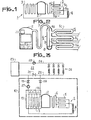
- - la figure 2 représente une vue schématique d'une partie du circuit de la figure 1,
- - la figure 3 représente une vue schématique du circuit frigorifique de la figure 1 appliqué à une pompe à chaleur réalisée selon l'invention,
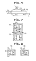
- - la figure 4 représente une vue schématique et partielle d'une coupe longitudinale d'une partie de l'échangeur thermique de la pompe à chaleur indiquée dans la figure 3,
- - la figure 5 représente une vue schématique et partielle d'une coupe verticale de la pompe à chaleur indiquée dans la figure 3, dans sa disposition compacte en un seul bloc,
- - la figure 6 représente à une autre échelle une vue schématique et partielle d'une coupe verticale de la pompe à chaleur indiquée dans la figure 3, dans sa disposition en deux parties,
- - la figure 7 représente à une autre échelle une vue schématique et partielle d'une coupe verticale d'une variante de réalisation de la pompe à chaleur indiquée dans la figure 3, dans sa disposition compacte, en un seul bloc, et
- - la figure 8 représente à une autre échelle une vue schématique et partielle d'une coupe verticale de la variante de réalisation de la figure 7, dans sa disposition en deux parties.
- FIG. 1 represents a schematic view of a refrigeration circuit with an evaporator of the dry type produced according to the invention,
- FIG. 2 represents a schematic view of part of the circuit of FIG. 1,
- FIG. 3 represents a schematic view of the refrigeration circuit of FIG. 1 applied to a heat pump produced according to the invention,
- FIG. 4 represents a schematic and partial view of a longitudinal section of a part of the heat exchanger of the heat pump indicated in FIG. 3,
- FIG. 5 represents a schematic and partial view of a vertical section of the heat pump indicated in FIG. 3, in its compact arrangement in a single block,
- FIG. 6 represents on another scale a schematic and partial view of a vertical section of the heat pump indicated in FIG. 3, in its arrangement in two parts,
- FIG. 7 shows on a different scale a schematic and partial view of a vertical section of an alternative embodiment of the heat pump indicated in FIG. 3, in its compact arrangement, in a single block, and
- - Figure 8 shows on another scale a schematic and partial view of a vertical section of the alternative embodiment of Figure 7, in its arrangement in two parts.
Un circuit frigorifique 1 réalisé selon l'invention comprend en circuit fermé principalement un motocompresseur 2, un condenseur 3, un capillaire 4 servant de détendeur et un évaporateur du type à sec 5.A refrigeration circuit 1 produced according to the invention comprises in closed circuit mainly a motor-
Dans ce circuit frigorifique, le réfrigérant gazeux est comprimé par le motocompresseur 2, refoulé dans le condenseur 3 où le réfrigérant se condense sous forme de liquide et cède de la chaleur.In this refrigeration circuit, the gaseous refrigerant is compressed by the motor-
Ce réfrigérant liquide traverse un détendeur constitué par un capillaire 4, se détend sous forme de brouillard ou fines gouttelettes dans l'évaporateur 5 où il s'évapore en absorbant de la chaleur autrement dit produit du froid avant de retourner au motocompresseur 2 sous l'action d'aspiration de ce dernier. Pratiquement le réfrigérant liquide résiduel restant dans l'évaporateur 5 est insignifiant ou faible. L'évaporateur 5 est ainsi appelé évaporateur du type à sec.This liquid refrigerant passes through a pressure reducer constituted by a capillary 4, expands in the form of mist or fine droplets in the evaporator 5 where it evaporates by absorbing heat in other words produces cold before returning to the motor-
Selon une caractéristique importante de l'invention, un collecteur composite vertical d'aspiration 6 est monté dans ce circuit frigorifique 1, entre le motocompresseur 2 et l'évaporateur 5.According to an important characteristic of the invention, a vertical composite suction manifold 6 is mounted in this refrigeration circuit 1, between the motor-
Selon une autre caractéristique de l'invention, l'évaporateur 5 est divisé en plusieurs sections verticalement espacées, montées en parallèle entre le détendeur 4 et le collecteur composite vertical d'aspiration 6. Les extrémités de sortie de ces sections débouchent respectivement sur différents points de la hauteur de ce collecteur composite d'aspiration 6. Le nombre de ces sections est supérieur ou égal à deux. Dans l'exemple illustré (figures 1 et 2) l'évaporateur 5 comprend trois sections superposées 5a, 5b, 5c montées en parallèle. La capacité de l'évaporateur et par conséquent celle de ses sections superposées et montées en parallèle sont déterminées de manière que dans le fonctionnement du circuit frigorifique 1, le réfrigérant liquide résiduel ne remplisse qu'au maximum une de ces sections de l'évaporateur 5, la section la plus basse 5a, et la partie inférieure du collecteur composite 6. De ce fait, une importante partie de l'évaporateur 5 reste constamment disponible pour la réception du brouillard de réfrigérant et pour l'évaporation de ce dernier. Le risque d'un retour du réfrigérant liquide dans le motocompresseur est ainsi efficacement évité. Un tel risque peut se produire plus facilement dans un circuit frigorifique à évaporateur du type humide dont une grande partie est remplie justement de réfrigérant sous forme de liquide.According to another characteristic of the invention, the evaporator 5 is divided into several vertically spaced sections, mounted in parallel between the
Le collecteur composite vertical 6 joue en plus de son rôle propre de collecteur d'aspiration, le rôle d'une bouteille anti-coup et celui d'un pulvérisateur-pompe réalisant sans dommage au motocompresseur 2, le retour à ce dernier, du lubrifiant et du réfrigérant liquide résiduel piégés dans le circuit.The vertical composite manifold 6 plays, in addition to its proper role as an intake manifold, the role of an anti-blow bottle and that of a sprayer-pump producing without damage to the
En effet, le réfrigérant gazeux détendu dans l'évaporateur 5, emprunte le collecteur vertical d'aspiration 6 pour retourner au motocompresseur 2, à travers une conduite de liaison 7.In fact, the gaseous refrigerant expanded in the evaporator 5 borrows the vertical suction manifold 6 to return to the motor-
La partie de lubrifiant du motocompresseur 2, entraînée par le courant de réfrigérant, et le réfrigérant liquide résiduel tendent, à la sortie de l'évaporateur 5, à se séparer du réfrigérant gazeux et à tomber vers le bas dans la partie inférieure 8 du collecteur vertical 6. Le collecteur 6 permet ainsi au réfrigérant gazeux de se débarrasser préalablement de réfrigérant liquide et de retourner seul sous forme gazeuse au motocompresseur 2. Les dommages mécaniques risquant d'être provoqués par un liquide pénétrant dans le compresseur sont de ce fait évités. Le collecteur composite vertical d'aspiration 6 joue ainsi en dehors de son rôle propre de collecteur d'aspiration, également le rôle d'une bouteille anti-coup et la remplace avantageusement.The lubricant part of the
Selon l'invention, le collecteur composite vertical 6 comprend d'une part un corps allongé 9 ayant une section transversale plus grande que celle de la conduite de liaison 7, fermé à son extrémité inférieure 8, rétréci à son extrémité supérieure 10 au niveau de son raccordement à cette conduite de liaison 7 et en communication en plusieurs points de sa paroi latérale avec l'évaporateur 5 et d'autre part dans l'enceinte de ce corps 9 et sur la presque totalité de la longueur de ce dernier, un capillaire 11 dont le bout inférieur est immergé dans la masse de lubrifiant et de réfrigérant liquide piégés dans l'extrémité inférieure 8 du collecteur 6 et le bout supérieur disposé coaxialement dans la partie rétrécie 10 de l'extrémité supérieure de ce collecteur. La partie rétrécie 10 de l'extrémité supérieure du collecteur 6 et le bout supérieur du capillaire 11 créent durant le passage du réfrigérant gazeux appelé par le motocompresseur 2, un venturi qui aspire du lubrifiant et du réfrigérant liquide, piégés dans la partie 8 du collecteur 6, les pulvérise et les mélange au courant de réfrigérant gazeux retournant au motocompresseur 2. Ce retour de réfrigérant liquide et de lubrifiant pulvérisés n'endommage pas le motocompresseur 2 mais élimine par ailleurs le défaut ou l'insuffisance de lubrification du motocompresseur rencontré dans les circuits frigorifiques connues.According to the invention, the vertical composite manifold 6 comprises on the one hand an elongated body 9 having a cross section larger than that of the connecting
Dans un circuit frigorifique à évaporateur du type humide, l'utilisation d'un tel pulvérisateur-pompe pour évacuer du réfrigérant liquide et du lubrifiant piégé n'est pratiquement pas envisageable étant donné que l'évaporateur de ce type est prévu justement pour être directement alimenté en réfrigérant sous forme de liquide dont l'évaporation produit du froid.In a refrigeration circuit with a wet type evaporator, the use of such a pump-sprayer to evacuate liquid refrigerant and trapped lubricant is practically not possible since the evaporator of this type is intended precisely to be directly supplied with refrigerant in the form of a liquid, the evaporation of which produces cold.
Dans son application à une pompe à chaleur 12 représentée à la figure 5 et indiquée par un rectangle en traits discontinus dans la figure 3, le circuit frigorifique 1 comprend un condenseur 3 qui forme avec un circuit indépendant de fluide caloporteur 14, un échangeur thermique 13 indiqué par un rectangle en traits discontinus. L'échangeur thermique 13 est selon l'invention constitué de préférence par deux circuits coaxiaux distincts 3 et 14 de deux fluides différents dont l'un est le réfrigérant comprimé chaud refoulé par le motocompresseur 2 et l'autre est un fluide caloporteur constitué de l'eau par exemple. Le circuit de fluide caloporteur 14 est constitué (figure 4) par une canalisation 15 montée coaxialement dans une conduite 16 formant le condenseur 3. La canalisation 15 dans laquelle circule le fluide caloporteur est, dans cet échangeur 13, entourée complètement par du réfrigérant comprimé chaud évoluant dans la conduite 16 du condenseur 3. L'échange thermique entre ces deux fluides peut ainsi se faire d'une manière efficace. Cette efficacité est renforcée quand le courant 17 de fluide caloporteur et le courant de réfrigérant comprimé chaud indiqué par les flèches 18 se dirigent dans des direction opposés. L'échangeur 13 constitue alors un échangeur à contre courants.In its application to a
Dans une contribution à un chauffage des locaux le circuit de fluide caloporteur 14 est raccordé, à travers deux vannes 19 et 20, par ses deux extrémités à l'entrée et à la sortie d'une vanne 21 d'un circuit de chauffage de locaux 22. Le circuit de chauffage 22 comprend par exemple une centrale connue de chauffage 23 qui envoie du fluide caloporteur chauffé, par des canalisations d'aller 24 et de retour 25 à un réseau de radiateurs 26.In a contribution to space heating, the heat
Quand la vanne 21 est fermée et les deux vannes 19 et 20 sont ouvertes, le fluide caloporteur venant du réseau des radiateurs 26 peut traverser à la fois l'échangeur 13 de la pompe à chaleur 12 et la centrale de chauffage 23 pour avoir un double apport de calories, avant de retourner aux radiateurs 26. Si la centrale 23 est au repos, la pompe à chaleur 12 peut assurer seule le chauffage et quand la pompe à chaleur 12 est au repos, la centrale 23 peut également assurer seule le chauffage. L'isolement du circuit de l'échangeur 13 de la pompe à chaleur peut être réalisé en fermant les vannes 19 et 20, la vanne 21 étant alors ouverte pour permettre au circuit de chauffage 22 de fonctionner normalement avec la centrale 23. Des circulateurs 27 et 28 peuvent être montés sur les circuits de l'échangeur 13 et de chauffage 22 pour accélérer la circulation du fluide caloporteur.When the
La pompe à chaleur 12 comprend de préférence deux éléments modulaires 47, 48 soit montables suivant une disposition en deux parties (figure 6) soit assemblables suivant une disposition compacte, en un seul bloc (figure 5).The
L'élément modulaire 47 comprend le motocompresseur 2 et l'échangeur 13, montés sur un socle thermiquement isolant 34 et fermés hermétiquement par une cloche thermiquement isolante 43. L'échangeur 13, est de préférence, disposé autour du motocompresseur 2 et appliqué contre sa carcasse. Selon cette structure toute la chaleur provenant du travail mécanique du moto- .compresseur 2 et de la compression de réfrigérant gazeux est maintenue prisonnière dans l'enceinte isolante définie par ces socle 34 et cloche 43 pour augmenter le potentiel d'échange thermique avec le fluide caloporteur circulant dans l'échangeur thermique 13.The
L'élément modulaire 48 comprend l'évaporateur 5 formant une paroi tubulaire ajourée, protégée au niveau de sa surface latérale extérieure par une grille ou ailettes de protection 42, un ventilateur 30 disposé dans la partie supérieure de l'évaporateur 5 pour engendrer un courant d'air 31, 32 qui traverse cet évaporateur de manière à favoriser un intense échange thermique entre l'air et le courant de réfrigérant dans l'évaporateur 5. L'évaporateur 5 est réchauffé par le courant d'air 31, 32. Le courant de réfrigérant dans l'évaporateur 5 puise de la chaleur dans cet air pour s'évaporer. L'air est déplacé latéralement suivant les flèches 31 et refoulé axialement vers le haut suivant les flèches 32 ou dans le sens inverse de ces flèches 31 et 32. Le ventilateur 30 est protégé par une grille 39 qui ferme l'extrémité supérieure de l'évaporateur 5.The
L'extrémité inférieure de cet évaporateur 5 repose sur une plaquette de fond 37.The lower end of this evaporator 5 rests on a
Dans une disposition en deux parties représentées schématiquement et partiellement dans la figure 6, les éléments modulaires 47 et 48 distants l'un de l'autre et faisant partie d'un même circuit frigorifique 1 sont reliés entre eux d'une manière connue par des canalisations non représentées, destinées à la circulation du réfrigérant. Le circuit de fluide caloporteur 14 de l'échangeur 13 de l'élément modulaire 47 est également raccordé d'une manière connue, au circuit de chauffage de locaux 22 par des canalisations non représentées.In an arrangement in two parts shown schematically and partially in Figure 6, the
Dans une disposition compacte, en un seul bloc ou monobloc, l'élément modulaire 48 est fixé sur le dessus de l'élément modulaire 47 (figure 5). Comme dans une dispositiôn en deux parties, les éléments modulaires 47 et 48 sont reliés entre eux par des canalisations non représentées du circuit frigorifique commun 1 tandis que le circuit de fluide caloporteur 14 de l'échangeur thermique 13 de l'élément modulaire 47 est raccordé au circuit de chauffage 22 par des canalisations non représentées.In a compact arrangement, in a single block or monobloc, the
Le raccordement de ces canalisations peut être avantageusement réalisé avec des coupleurs rapides de type connu non représentés.The connection of these pipes can be advantageously carried out with quick couplers of known type not shown.
Les eaux de ruissellement qui, pénétrant dans l'élément modulaire 48 se rassemblent sur la plaquette de fond 37 de ce dernier sont évacuées au moyen de gorges non représentées, formées dans la surface supérieure de cette plaquette 37. Ces gorges sont orientées de manière à amener les eaux de ruissellement soit jusqu'au bord périphérique de la plaquette de fond 37 pour les évacuer par déversement soit jusqu'à un trou de passage 41 débouchant dans une conduite d'évacuation 46 formée dans l'épaisseur de la paroi verticale de la cloche isolante 43 de l'élément modulaire 47.The runoff which, entering the
La liaison mécanique de fixation entre les éléments modulaires 47 et 48 est obtenue selon une technique connue non décrite et avec des moyens de fixation connus non représentés.The mechanical fixing connection between the
Dans une variante de réalisation représentée schématiquement et partiellement aux figures 7 et 8, l'évaporateur 5 est réchauffé par un courant de liquide. Ce liquide réchauffeur peut être une eau de rivière, de forage ou d'une nappe naturelle, une eau usée récupérée, ou un liquide réchauffeur faisant partie d'un circuit fermé enterré. L'évaporateur 5 et le circuit de liquide réchauffeur constitue un échangeur de chaleur 44 réalisé de manière analogue à celle de l'échangeur thermique 13 avec par exemple des canalisations semblables à celles représentées à la figure 4, montées coaxialement l'une par rapport à l'autre. Dans cet échangeur de chaleur 44 la canalisation centrale 51 destinée à la circulation du réfrigérant détendu, constitue un circuit évaporateur 51 tandis que la canalisation extérieure 52, réservée à l'écoulement du liquide réchauffeur, constitue un circuit réchauffeur 52.In an alternative embodiment shown schematically and partially in Figures 7 and 8, the evaporator 5 is heated by a stream of liquid. This heating liquid can be river, borehole or natural water, recovered waste water, or a heating liquid forming part of a closed underground circuit. The evaporator 5 and the heating liquid circuit constitutes a
Dans cette variante de réalisation, la pompe à chaleur 12 comprend également deux éléments modulaires 49, 50 montables suivant une disposition en deux parties (figure 8) ou assemblables suivant une disposition compacte, en un seul bloc ou monobloc (figure 7).In this variant embodiment, the
L'élément modulaire 49 comprend une structure analogue ou de préférence identique à celle de l'élément modulaire 47 des figures 5 et 6, à savoir le motocompresseur 2, l'échangeur thermique 13, le socle isolant 34 et la cloche isolante 43.The
L'élément modulaire 50 comprend un échangeur de chaleur 44 monté sur une plaquette de base 46 et protégé par une cloche 45. La cloche de protection 45 peut avoir soit une paroi ajourée et non thermiquement isolante soit une paroi pleine et thermiquement isolante. Quand la cloche de protection 45 est formée d'une paroi pleine et thermiquement isolante, seul le fluide réchauffeur constitue la source de chaleur pour le réfrigérant. Quand la cloche de protection 45 est ajourée, la chaleur du milieu environnant s'ajoute au fluide réchauffeur pour constituer les sources de chaleur au réfrigérant de l'évaporateur 5 du circuit frigorifique 1. Des gorges non représentées sont également formées dans la plaque de base 46 pour évacuer les eaux de ruissellement pénétrant dans l'élément modulaire 50.The
La pompe à chaleur 12 ainsi construite est solide et peut résister aux agressions mécaniques et d'intempéries tout en réalisant une excellente performance dans son fonctionnement, et restant économique dans sa fabrication par la simplicité de sa structure.The
Claims (12)
Applications Claiming Priority (2)
| Application Number | Priority Date | Filing Date | Title |
|---|---|---|---|
| FR8123738A FR2518720A1 (en) | 1981-12-18 | 1981-12-18 | MOTORIZED REFRIGERATOR CIRCUIT, AND HEAT PUMP PROVIDED WITH SUCH A CIRCUIT |
| FR8123738 | 1981-12-18 |
Publications (1)
| Publication Number | Publication Date |
|---|---|
| EP0082764A1 true EP0082764A1 (en) | 1983-06-29 |
Family
ID=9265192
Family Applications (1)
| Application Number | Title | Priority Date | Filing Date |
|---|---|---|---|
| EP82402289A Withdrawn EP0082764A1 (en) | 1981-12-18 | 1982-12-14 | Refrigeration circuit with motor compressor, and heat pump provided with such a circuit |
Country Status (2)
| Country | Link |
|---|---|
| EP (1) | EP0082764A1 (en) |
| FR (1) | FR2518720A1 (en) |
Cited By (4)
| Publication number | Priority date | Publication date | Assignee | Title |
|---|---|---|---|---|
| FR2644357A1 (en) * | 1989-03-14 | 1990-09-21 | Selnor Electromenager Nord | Liquid-gas separator and device comprising such a separator |
| WO2013023630A3 (en) * | 2011-08-16 | 2013-05-23 | Ixetic Bad Homburg Gmbh | Compact heating and cooling module, and use of a compact heating and cooling module |
| WO2013113308A1 (en) * | 2012-02-02 | 2013-08-08 | Ixetic Bad Homburg Gmbh | Compressor-heat exchanger unit for a heating-cooling module for a motor vehicle |
| CN104236164A (en) * | 2014-09-15 | 2014-12-24 | 美意(浙江)空调设备有限公司 | Ultra-high temperature cascade water source heat pump system |
Families Citing this family (1)
| Publication number | Priority date | Publication date | Assignee | Title |
|---|---|---|---|---|
| CN109677236B (en) * | 2018-12-26 | 2021-10-15 | 四川赛特制冷设备有限公司 | Air conditioning system of electric vehicle |
Citations (20)
| Publication number | Priority date | Publication date | Assignee | Title |
|---|---|---|---|---|
| FR830861A (en) * | 1936-12-17 | 1938-08-11 | Thomson Houston Comp Francaise | Improvements to refrigeration systems |
| US2362698A (en) * | 1934-10-24 | 1944-11-14 | Gen Motors Corp | Refrigerating apparatus |
| US2516094A (en) * | 1949-05-17 | 1950-07-18 | V C Patterson & Associates Inc | Heat pump water heater |
| DE1102187B (en) * | 1957-03-05 | 1961-03-16 | Heat Pump & Refrigeration Ltd | Heat pump system |
| GB891573A (en) * | 1960-05-31 | 1962-03-14 | Heat Pump & Refrigeration Ltd | Improvements in or relating to heat pump systems |
| US3512374A (en) * | 1968-05-03 | 1970-05-19 | Parker Hannifin Corp | Suction accumulator for refrigeration systems |
| US3513663A (en) * | 1968-05-08 | 1970-05-26 | James B Martin Jr | Apparatus for heating and cooling liquids |
| FR2191089A1 (en) * | 1972-07-03 | 1974-02-01 | Ciat Sa | |
| FR2320511A1 (en) * | 1975-08-05 | 1977-03-04 | Commissariat Energie Atomique | Heat pump with noise reducing housing - has thermostatic valve at evaporator outlet and pressure reducer between condenser and evaporator |
| DE2604942A1 (en) * | 1976-02-09 | 1977-08-11 | Karl Dr Ing Schmidt | HEAT PUMP |
| DE2624482A1 (en) * | 1976-06-01 | 1977-12-15 | Babcock Ag | Removal of unwanted components from exhaust gases - using moving beds of activated carbon in several levels |
| US4138859A (en) * | 1977-11-02 | 1979-02-13 | General Electric Company | Split heat pump outdoor fan arrangement |
| DE2841711A1 (en) * | 1978-09-25 | 1980-04-03 | Dieter Dipl Ing Fleischer | Vaporiser with superheating control - incorporates separator for liquid and by=pass nozzle tube for signal emitter |
| EP0009786A1 (en) * | 1978-10-02 | 1980-04-16 | Küppersbusch Aktiengesellschaft | Heating system comprising a heating pump |
| FR2455254A1 (en) * | 1979-04-27 | 1980-11-21 | Bracht Armand | Condenser and compressor unit for heat pump - has compressor enclosed by condenser coil inside common housing with evaporator outside |
| FR2475686A1 (en) * | 1980-02-09 | 1981-08-14 | Viessmann Hans | Box section mounting frame for refrigerator heat pump - has sheet metal H=section and is fixed on base with evaporator mounted on top shelf |
| FR2487056A1 (en) * | 1980-07-18 | 1982-01-22 | Froid Ste Toulousaine | Cooling or reheating of liq. in mobile tank - where liq. is circulated through external heat exchanger, and tank is mounted on lorry or wagon used to transport the liq. |
| US4320630A (en) * | 1980-11-06 | 1982-03-23 | Atlantic Richfield Company | Heat pump water heater |
| GB2092731A (en) * | 1981-02-10 | 1982-08-18 | Bosch Siemens Hausgeraete | Heat pump |
| DE3103362A1 (en) * | 1981-01-28 | 1982-08-19 | Harry 2351 Großenaspe Haase | Heat recovery installation according to the principle of the heat pump |
Family Cites Families (8)
| Publication number | Priority date | Publication date | Assignee | Title |
|---|---|---|---|---|
| CH135573A (en) * | 1928-06-16 | 1929-09-30 | Escher Wyss Maschf Ag | Evaporator for refrigeration systems, which has one or more bundles of coils. |
| US2042812A (en) * | 1934-02-23 | 1936-06-02 | Westinghouse Electric & Mfg Co | Refrigeration apparatus |
| US2700279A (en) * | 1952-06-12 | 1955-01-25 | Gen Motors Corp | Refrigerating apparatus and water heater |
| DE1051295B (en) * | 1957-02-16 | 1959-02-26 | Wilhelm Bock | Condenser unit for refrigeration machines |
| US3483714A (en) * | 1968-07-05 | 1969-12-16 | Virginia Chemicals Inc | Liquid trapping device |
| DE2452346A1 (en) * | 1974-11-05 | 1976-05-06 | Virginia Chemicals Inc | Liquid trap in motor vehicle refrigeration circuit - made more effective by combining pressure regulator with trap |
| DE2602582C2 (en) * | 1976-01-21 | 1983-03-31 | Erich Schultze KG, 1000 Berlin | Liquid separator for refrigeration systems |
| DE2634482A1 (en) * | 1976-07-31 | 1978-02-02 | Goetzewerke | Compact heat pump for warming small swimming pool - has coaxial condenser wound spirally round compressor |
-
1981
- 1981-12-18 FR FR8123738A patent/FR2518720A1/en active Granted
-
1982
- 1982-12-14 EP EP82402289A patent/EP0082764A1/en not_active Withdrawn
Patent Citations (20)
| Publication number | Priority date | Publication date | Assignee | Title |
|---|---|---|---|---|
| US2362698A (en) * | 1934-10-24 | 1944-11-14 | Gen Motors Corp | Refrigerating apparatus |
| FR830861A (en) * | 1936-12-17 | 1938-08-11 | Thomson Houston Comp Francaise | Improvements to refrigeration systems |
| US2516094A (en) * | 1949-05-17 | 1950-07-18 | V C Patterson & Associates Inc | Heat pump water heater |
| DE1102187B (en) * | 1957-03-05 | 1961-03-16 | Heat Pump & Refrigeration Ltd | Heat pump system |
| GB891573A (en) * | 1960-05-31 | 1962-03-14 | Heat Pump & Refrigeration Ltd | Improvements in or relating to heat pump systems |
| US3512374A (en) * | 1968-05-03 | 1970-05-19 | Parker Hannifin Corp | Suction accumulator for refrigeration systems |
| US3513663A (en) * | 1968-05-08 | 1970-05-26 | James B Martin Jr | Apparatus for heating and cooling liquids |
| FR2191089A1 (en) * | 1972-07-03 | 1974-02-01 | Ciat Sa | |
| FR2320511A1 (en) * | 1975-08-05 | 1977-03-04 | Commissariat Energie Atomique | Heat pump with noise reducing housing - has thermostatic valve at evaporator outlet and pressure reducer between condenser and evaporator |
| DE2604942A1 (en) * | 1976-02-09 | 1977-08-11 | Karl Dr Ing Schmidt | HEAT PUMP |
| DE2624482A1 (en) * | 1976-06-01 | 1977-12-15 | Babcock Ag | Removal of unwanted components from exhaust gases - using moving beds of activated carbon in several levels |
| US4138859A (en) * | 1977-11-02 | 1979-02-13 | General Electric Company | Split heat pump outdoor fan arrangement |
| DE2841711A1 (en) * | 1978-09-25 | 1980-04-03 | Dieter Dipl Ing Fleischer | Vaporiser with superheating control - incorporates separator for liquid and by=pass nozzle tube for signal emitter |
| EP0009786A1 (en) * | 1978-10-02 | 1980-04-16 | Küppersbusch Aktiengesellschaft | Heating system comprising a heating pump |
| FR2455254A1 (en) * | 1979-04-27 | 1980-11-21 | Bracht Armand | Condenser and compressor unit for heat pump - has compressor enclosed by condenser coil inside common housing with evaporator outside |
| FR2475686A1 (en) * | 1980-02-09 | 1981-08-14 | Viessmann Hans | Box section mounting frame for refrigerator heat pump - has sheet metal H=section and is fixed on base with evaporator mounted on top shelf |
| FR2487056A1 (en) * | 1980-07-18 | 1982-01-22 | Froid Ste Toulousaine | Cooling or reheating of liq. in mobile tank - where liq. is circulated through external heat exchanger, and tank is mounted on lorry or wagon used to transport the liq. |
| US4320630A (en) * | 1980-11-06 | 1982-03-23 | Atlantic Richfield Company | Heat pump water heater |
| DE3103362A1 (en) * | 1981-01-28 | 1982-08-19 | Harry 2351 Großenaspe Haase | Heat recovery installation according to the principle of the heat pump |
| GB2092731A (en) * | 1981-02-10 | 1982-08-18 | Bosch Siemens Hausgeraete | Heat pump |
Cited By (5)
| Publication number | Priority date | Publication date | Assignee | Title |
|---|---|---|---|---|
| FR2644357A1 (en) * | 1989-03-14 | 1990-09-21 | Selnor Electromenager Nord | Liquid-gas separator and device comprising such a separator |
| WO2013023630A3 (en) * | 2011-08-16 | 2013-05-23 | Ixetic Bad Homburg Gmbh | Compact heating and cooling module, and use of a compact heating and cooling module |
| WO2013113308A1 (en) * | 2012-02-02 | 2013-08-08 | Ixetic Bad Homburg Gmbh | Compressor-heat exchanger unit for a heating-cooling module for a motor vehicle |
| US9551516B2 (en) | 2012-02-02 | 2017-01-24 | Magna Powertrain Bad Homburg GmbH | Compressor-heat exchanger unit for a heating-cooling module for a motor vehicle |
| CN104236164A (en) * | 2014-09-15 | 2014-12-24 | 美意(浙江)空调设备有限公司 | Ultra-high temperature cascade water source heat pump system |
Also Published As
| Publication number | Publication date |
|---|---|
| FR2518720A1 (en) | 1983-06-24 |
| FR2518720B1 (en) | 1984-09-14 |
Similar Documents
| Publication | Publication Date | Title |
|---|---|---|
| EP0046716B1 (en) | Cooling apparatus comprising a radiant panel and an evaporative panel | |
| EP0774102B1 (en) | Condenser with a built-in receiver for a motor vehicle air conditioning unit | |
| FR2765956A1 (en) | REFRIGERANT CONDENSER INCLUDING A SUPER-COOLING PART | |
| EP0010118A1 (en) | Heat exchanger, especially for an atmospheric cooler | |
| FR2966913A1 (en) | THERMAL EXCHANGE SYSTEM BETWEEN AIR SITUATED WITHIN A SPACE AND AIR SITUATED OUTSIDE OF THE SPACE AND METHOD FOR CARRYING OUT THERMAL EXCHANGE USING SUCH A SYSTEM | |
| EP0082764A1 (en) | Refrigeration circuit with motor compressor, and heat pump provided with such a circuit | |
| FR2465979A1 (en) | CONDENSER WITH HEAT TRANSFER CHARACTERISTICS | |
| FR2724220A1 (en) | WET ATMOSPHERIC REFRIGERANT WITH ANTIFREEZE DEVICE | |
| EP0320379B1 (en) | Absorption air conditioning equipment | |
| FR2505999A1 (en) | METHOD AND APPARATUS FOR CONDENSING STEAM TO CONTINUOUSLY EXTRACT CONDENSATE FROM COMPRESSED GAS CURRENT | |
| FR2548769A1 (en) | Heating installation with heat pumps and collectors for atmospheric energy | |
| EP0187571B1 (en) | Thermal energy collector and device having such a collector | |
| CH635669A5 (en) | MACHINE FOR THE MANUFACTURE OF GLACONS | |
| FR2505465A1 (en) | IMPROVED DEFROSTING SYSTEM FOR REVERSIBLE CYCLE HEAT PUMPS | |
| EP0229410A1 (en) | Refrigeration machine | |
| CA1087409A (en) | Heat exchange system using refrigerant | |
| FR2487488A1 (en) | HEAT PUMP | |
| FR2850122A1 (en) | Water extracting device for e.g. cultivating land in semi-desert zone, has cool plates arranged parallely in pumping chamber that forms predetermined horizontal angle to collect water by simple gravity | |
| FR2524126A1 (en) | Heat storage reservoir for heat pump - where latent heat of solidification of water provides heat for evaporator in heat pump circuit | |
| LU86935A1 (en) | PROCESS FOR THE PRESERVATION OF FLOWERS AND / OR PLANTS ARRANGED IN A PREMISES AND DEVICE USED FOR THIS PROCESS | |
| FR2706531A1 (en) | Expansion tank (vessel) for a heat engine cooling circuit | |
| EP1248062A1 (en) | Water vapour condenser | |
| FR2570172A1 (en) | Improved multi-tube exchanger | |
| FR2672114A1 (en) | Refrigeration units for refrigerated chambers and refrigeration installation using such units | |
| FR2721697A1 (en) | Very large autonomous refrigerated cabinet |
Legal Events
| Date | Code | Title | Description |
|---|---|---|---|
| PUAI | Public reference made under article 153(3) epc to a published international application that has entered the european phase |
Free format text: ORIGINAL CODE: 0009012 |
|
| AK | Designated contracting states |
Designated state(s): AT BE DE FR GB IT NL |
|
| 17P | Request for examination filed |
Effective date: 19831117 |
|
| STAA | Information on the status of an ep patent application or granted ep patent |
Free format text: STATUS: THE APPLICATION IS DEEMED TO BE WITHDRAWN |
|
| 18D | Application deemed to be withdrawn |
Effective date: 19850623 |
|
| RIN1 | Information on inventor provided before grant (corrected) |
Inventor name: BIANIC, CHRISTIAN |