EP0082610A1 - Container pour chemin de fer et wagon - Google Patents
Container pour chemin de fer et wagon Download PDFInfo
- Publication number
- EP0082610A1 EP0082610A1 EP82306327A EP82306327A EP0082610A1 EP 0082610 A1 EP0082610 A1 EP 0082610A1 EP 82306327 A EP82306327 A EP 82306327A EP 82306327 A EP82306327 A EP 82306327A EP 0082610 A1 EP0082610 A1 EP 0082610A1
- Authority
- EP
- European Patent Office
- Prior art keywords
- container
- spine
- central
- skirts
- car
- Prior art date
- Legal status (The legal status is an assumption and is not a legal conclusion. Google has not performed a legal analysis and makes no representation as to the accuracy of the status listed.)
- Granted
Links
- 230000002093 peripheral effect Effects 0.000 claims abstract description 21
- 238000003860 storage Methods 0.000 claims description 5
- 239000011152 fibreglass Substances 0.000 claims description 4
- 229910001234 light alloy Inorganic materials 0.000 claims description 2
- NJPPVKZQTLUDBO-UHFFFAOYSA-N novaluron Chemical compound C1=C(Cl)C(OC(F)(F)C(OC(F)(F)F)F)=CC=C1NC(=O)NC(=O)C1=C(F)C=CC=C1F NJPPVKZQTLUDBO-UHFFFAOYSA-N 0.000 claims 1
- 230000005484 gravity Effects 0.000 abstract description 6
- 238000003892 spreading Methods 0.000 abstract description 3
- 238000005192 partition Methods 0.000 description 3
- XLYOFNOQVPJJNP-UHFFFAOYSA-N water Substances O XLYOFNOQVPJJNP-UHFFFAOYSA-N 0.000 description 3
- 239000000463 material Substances 0.000 description 2
- 229910000838 Al alloy Inorganic materials 0.000 description 1
- FYYHWMGAXLPEAU-UHFFFAOYSA-N Magnesium Chemical compound [Mg] FYYHWMGAXLPEAU-UHFFFAOYSA-N 0.000 description 1
- 229910000861 Mg alloy Inorganic materials 0.000 description 1
- 229910045601 alloy Inorganic materials 0.000 description 1
- 239000000956 alloy Substances 0.000 description 1
- XAGFODPZIPBFFR-UHFFFAOYSA-N aluminium Chemical compound [Al] XAGFODPZIPBFFR-UHFFFAOYSA-N 0.000 description 1
- 239000003245 coal Substances 0.000 description 1
- 238000004891 communication Methods 0.000 description 1
- 238000010276 construction Methods 0.000 description 1
- 239000003562 lightweight material Substances 0.000 description 1
- 239000011777 magnesium Substances 0.000 description 1
- 238000004519 manufacturing process Methods 0.000 description 1
- 238000000034 method Methods 0.000 description 1
- 238000012986 modification Methods 0.000 description 1
- 230000004048 modification Effects 0.000 description 1
- 238000005086 pumping Methods 0.000 description 1
- 230000002787 reinforcement Effects 0.000 description 1
- 230000003014 reinforcing effect Effects 0.000 description 1
- 229910001256 stainless steel alloy Inorganic materials 0.000 description 1
- 230000007704 transition Effects 0.000 description 1
Images


Classifications
-
- B—PERFORMING OPERATIONS; TRANSPORTING
- B61—RAILWAYS
- B61D—BODY DETAILS OR KINDS OF RAILWAY VEHICLES
- B61D3/00—Wagons or vans
- B61D3/16—Wagons or vans adapted for carrying special loads
- B61D3/20—Wagons or vans adapted for carrying special loads for forwarding containers
-
- B—PERFORMING OPERATIONS; TRANSPORTING
- B61—RAILWAYS
- B61F—RAIL VEHICLE SUSPENSIONS, e.g. UNDERFRAMES, BOGIES OR ARRANGEMENTS OF WHEEL AXLES; RAIL VEHICLES FOR USE ON TRACKS OF DIFFERENT WIDTH; PREVENTING DERAILING OF RAIL VEHICLES; WHEEL GUARDS, OBSTRUCTION REMOVERS OR THE LIKE FOR RAIL VEHICLES
- B61F1/00—Underframes
- B61F1/08—Details
- B61F1/14—Attaching or supporting vehicle body-structure
-
- B—PERFORMING OPERATIONS; TRANSPORTING
- B61—RAILWAYS
- B61D—BODY DETAILS OR KINDS OF RAILWAY VEHICLES
- B61D3/00—Wagons or vans
- B61D3/10—Articulated vehicles
- B61D3/12—Articulated vehicles comprising running gear interconnected by loads
-
- B—PERFORMING OPERATIONS; TRANSPORTING
- B61—RAILWAYS
- B61F—RAIL VEHICLE SUSPENSIONS, e.g. UNDERFRAMES, BOGIES OR ARRANGEMENTS OF WHEEL AXLES; RAIL VEHICLES FOR USE ON TRACKS OF DIFFERENT WIDTH; PREVENTING DERAILING OF RAIL VEHICLES; WHEEL GUARDS, OBSTRUCTION REMOVERS OR THE LIKE FOR RAIL VEHICLES
- B61F3/00—Types of bogies
- B61F3/12—Types of bogies specially modified for carrying adjacent vehicle bodies of articulated trains
Definitions
- This invention relates to an improved railway container for transporting bulk cargo on specially adapted railway cars, and to railway cars configured to transport such containers.
- the railway cars and containers described in the Adams patent suffer from certain limitations.
- the center of gravity of the cargo being carried is situated at a relatively high level, because none of the cargo is carried below the uppermost level of the railway car itself.
- Such a high center of 'gravity can be undesirable particularly when heavy cargos, such as bulk grains, for example, are being transported.
- containers such as those shown in the Adams patent are rectangular and do not therefore provide an aerodynamically contoured shape. For this reason, energy losses due to wind resistance around the trucks of the railway car and around the containers themselves are unnecessarily high.
- many containers of the type shown by Adams are adapted for use with palletized cargo. Bulk cargos, such as grain or coal for example, often cannot be transported in such containers efficiently. This is due to the fact that many standard rectangular containers do not have adequate structural strength to contain a full load of a heavy bulk cargo.
- this invention is directed to an improved container for bulk cargo which is strong and light in weight, which provides excellent aerodynamic characteristics when being transported on a railway car, which provides an exceptionally low center of gravity when used to transport bulk cargos, and which can be efficiently stacked for storage or transport.
- an improved container which comprises a peripheral wall, a bottom section secured to the lower edge of the wall, and a top section secured to an upper edge of the wall.
- the bottom section of this container defines a raised elongated central recess and a pair of longitudinally downwardly extending skirts, one on either side of the central recess.
- the top section of the container defines a central ridge positioned over the central recess of the bottom section such that the top section defines a contour which generally matches that of the bottom section to facilitate stacking of the container.
- the container of this invention is configured to be transported on a railway car of the type having a central, longitudinally extending spine which is supported at each end by a respective truck.
- the central recess of the-bottom section overlies the spine of the car and each of the skirts is positioned alongside and below the top of the spine between the trucks.
- These skirts communicate directly with the interior of the container such that the skirts form a cargo carrying portion of the container.
- a respective longitudinally extending lower bulk cargo hatch is provided along the lowermost portion of each of the skirts, and a longitudinally extending upper bulk cargo hatch is provided along the uppermost portion of the central ridge.
- this preferred embodiment includes a perforated floor extending across the interior of the container above the skirts, and an end door or side door mounted in the peripheral wall to admit palletized cargo into the container to be supported by the perforated floor.
- this container makes extensive use of fiberglass or light alloy panels to minimize the weight of the container.
- the railway car which is used to transport the container of this invention includes at least two container attachment structures, each mounted to the spine to extend below an upper surface of the spine such that each of the attachment structures contacts the container at a point lower than the upper surface of the spine in order securely to mount the container to the car.
- the container of this invention can be mounted to the railway car of this invention by means of these attachment structures.
- two or more containers can be stacked one above the other, with the central ridge of the lower container extending into the longitudinally extended central recess between the skirts of the upper container.
- novel container and railway car of this invention provide a number of significant advantages over conventional rectangular containers, as will be described in detail below.
- the preferred embodiments of the container of this invention provide an unusually low center of gravity when used to transport bulk cargo, that they provide excellent aerodynamic characteristics, that they are strong and light in weight and well suited for transporting heavy bulk cargos, that they can be stacked when necessary for storage or transport, and that they can be used to transport either bulk or palletized cargo.
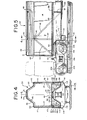
- FIGS. 1 through 6 depict various views of a first preferred embodiment of the container and railway car of this invention.
- the container 10 includes two spaced, parallel side walls 12,14 and two spaced, parallel end walls 16,18.
- the side walls 12,14 and end walls 16,18 cooperate to define a peripheral wall which extends around the perimeter of the container 10. This peripheral wall is enclosed at its lower edge by a bottom 20 and at its upper edge by a top 30.
- the bottom 20 is made up of three sections: a central section 22 which extends centrally and longitudinally down the length of the container 10, and two side sections 24,26 which extend below the central section 22 along the length of the container 10.
- the central section 22 cooperates with the side sections 24,26 to define an elongated, longitudinally oriented central recess 28 which extends from end to end of the container 10.
- the top 30 defines a central ridge 31 which is bounded on either side by a respective sloping side panel 32,33. As shown in FIG. 4, the central ridge 31 defines a shape or contour which corresponds to that of the central recess 28. As will be explained in detail below in connection with FIGS. 6 and 7, this correspondence between the contour of the bottom 20 and the top 30 plays an important role when the container 10 is stacked.
- the side sections 24,26 of the bottom 20 cooperate with the lower portions of the side walls 12,14 to define two elongated skirts 34,36.
- the skirts 34,36 are in communication with the interior of the container 10 and serve as a portion of the cargo carrying volume of the container 10.
- the container 10 includes an interior framework of stiffening elements which strengthen the container 10 so as to make it self-supporting.
- This framework includes four vertically oriented uprights 37, two of which are affixed to each of the side walls 12,14.
- each of the uprights 37 is formed of a hollow, rectangular member.
- the upper ends of each of the uprights 37 extend through the top 30 and serve to define respective upper anchor members 40.
- the lower ends of each of the uprights 37 extend through the bottom 20 and serve to define lower anchor members 38.
- the anchor members 38,40 serve to receive spring-loaded latches used to secure the container 10 in place, either on the railway car, or on another container.
- each of the uprights 37 defines two side lifting recesses 41, which can be used as lifting points to attach cranes and the like to lift the container 10.
- the uprights 37 serve to strengthen and support the side walls 12,14, to transmit loads via the anchor members 38,40 to underlying support surfaces, and to transmit loads via the side lifting recess 41 to lifting structures.
- the frame includes frame diagonals 42 which extend from the uprights 37 as shown in FIG. 2 and are bonded to the side walls 12,14. These diagonals 42 serve further to strengthen and support the side walls 12,14.
- a plurality of arches 43 which are secured to the top 30 so as to brace and reinforce the top 30. The two outermost arches 43 are rigidly secured to the respective uprights 37, while the three inner arches 43 are bonded directly to the top 30.
- a plurality of partitions 47 are mounted to extend completely across the. skirts 34,36 ; . such that each of the skirts 34,36 is divided into four sections. These partitions 47 are mounted between the lower portions of the side walls 12,14 and the side sections 24,26 as shown in FIG. 4 in order to reinforce and strengthen the skirts 34,36.
- two air ducts 50,52 are bonded to the side walls 12,14 above'the skirts 34,36.
- Each of these air ducts 50,52 is rectangular in cross section and hollow, and the ducts 50,52 serve simultaneously as structural members to strengthen and support the side walls 12,14 and as conduits to pass treated air along the length of the container 10.
- a sill 49 is mounted on the bottom 20 within the container 10 directly above the central section 22. This sill 49 extends longitudinally along the length of the container 10, parallel to the air ducts 50,52, and it serves as a further longitudinally reinforcing structural member. As shown in FIG. 4 the sill 49 is preferably hollow so as to provide an air passage extending along the length of the container 10.
- a perforated floor 58 is mounted between the air ducts 50,52 above the skirts 34,36. This perforated floor 58 acts in tension to prevent the side walls 12,14 from spreading.
- the perforated floor 58 is provided with large perforations which act to allow bulk cargo such as grain to pass through the floor as necessary.
- the perforations in the floor 58 are preferably sufficiently small so as to allow palletized cargo and loading equipment such as forklifts to be supported adequately by the floor 58.
- the container 10 is provided with a number of doors and hatches.
- An upper bulk cargo door or hatch 44 extends.along the length of the central ridge 31.
- the upper hatch 44 is formed of a fiberglass panel hinged along one edge to the top 30.
- the hatch 44 can be made of one elongated panel which extends along the entire length of the ridge 31. Alternately, the upper hatch 44 can be segmented into a number of separate doors. Whatever the configuration chosen for the upper hatch 44, it should be dust- and weatherproof so as to prevent the entry of water or moisture into the container once the hatch 44 has been closed and secured.
- the upper hatch 44 is used for loading bulk cargo into the container 10.
- the container 10 also includes two lower bulk cargo doors or hatches 46, each of which extends along the lowermost portion of a respective one of the two skirts 34,36. These lower doors 46 are used for unloading bulk cargos from the container 10, and they also provide further longitudinal reinforcement to the container 10.
- Various types of weatherproof and leakproof doors can be used for the lower doors 46; however, in this preferred embodiment the doors 46 are rotating cylindrical doors such as those marketed by Morrison-Knudson Co., Inc. of Boise, Idaho, U.S.A.
- the length of the lower doors 46 can be chosen to fit the individual application.
- each of the lower doors 46 is made up of four 10-foot (3 meters) segments, each extending between adjacent partitions 47. Of course, segments of other lengths may well be suited for use in alternative embodiments.
- the container 10 also includes two end doors 48, each of which is mounted in a respective end wall 16,18 to provide access to the interior of the container above the floor 58.
- These end.doors 48 are..mounted on hinges to the respective end walls 16,18, so as to open in the conventional manner.
- the doors 48 should provide a weather-proof seal once closed and secured.
- the air ducts 50,52 and the interior of the sill 49 are all connected to manifolds 55 which extend across each end of the container 10. Both the air ducts 50,52 and the sill 49 define downwardly directing air nozzles 56. These nozzles 56 serve to direct air from the interior of the ducts 50,52 and the sill 49 into the interior of the container 10.
- the manifolds 55 are adapted to be connected by conventional means, not shown, to a source of treated air.
- the manifolds 55, ducts 50,52 and sill 49 can be coupled to a pumping unit (not shown) for supplying heated, dried air in order to dry the contents of the container 10.
- each end of the container 10 is provided with rounded corners 60 which provide a smooth, rounded transition between the end walls 16,18 and the side walls 12,14 and the top 30. These rounded corners 60 provide smooth, aerodynamically efficient surfaces which reduce air turbulence and air drag when the container 10 is transported.
- each of the skirts 34,36 defines a respective wheel well 62 at each end thereof. As will be explained below, these wheel wells 62 serve to reduce air turbulence around the trucks of the railway car on which the container 10 is transported, thereby further reducing wind drag and related loses.
- the preferred embodiment of the container 10 described above is constructed with the following preferred dimensions.
- the width of the container between the side walls 12,14 is eight feet (2.4 meters).
- the height of the container 10 between the lowermost portion of the skirts 34,36 and the uppermost portion of the ridge 31 is 10 feet, 3 inches (3.12 meters).
- the height of the central ridge 31 is 30 inches (76 cm) and the height of the central recess 28 is also 30 inches (76 cm).
- the length of the container 10 between the end walls 16,18 is 45 feet (13.7 meters), and the length of the container 10 between the uprights 37 is 35 feet (10.7 meters).
- the rounded corners 60 are provided with a radius curvature of 8 inches (20 cm), and the width of both the central section 22 and the uppermost surface of the central ridge 31 is 24 inches (61 cm).
- the container 10 has been designed to maximize the use of light weight materials.
- Alternative embodiments can employ either fiberglass or light weight alloy panels formed of aluminum, magnesium or stainless steel alloys to make up the side walls 12,14, the end walls 16,18, the bottom 20 and the top 30.
- fiberglass or light weight alloy panels formed of aluminum, magnesium or stainless steel alloys to make up the side walls 12,14, the end walls 16,18, the bottom 20 and the top 30.
- these elements have been discussed separately, it should be emphasized that with many fabrication techniques, multiple panels may be formed as a single unit.
- the weight of the container 10 can be minimized, while providing an adequate strength to allow the entire internal volume of the container 10 to be filled with bulk cargo such as grain.
- the side walls are corrugated in the longitudinal direction in order further to strengthen the car 10.
- the contour of the bottom 20 and the rounded corners 60 provide additional structural strength.
- the container 10 can be mounted on a railway car 100.
- This railway car 100 includes a longitudinally extending central spine 102 which is supported at each end by a respective truck 104,106.
- Each of the trucks 104,106 includes a plurality of wheels 108, each of which rotates about a respective rotational axis 109.
- FIG. 4- is a sectional view which shows one of the two container bolsters 110 which are mounted to each of the cars 100.
- Each container bolster 110 is made up of two spaced, parallel plates which are securely fastened to the spine 102 so as to extend transversely to the spine 102.
- Each of the bolsters 110 defines two spaced container pedestals 110, one on either side of the spine 102.
- Each of the pedestals 112 defines a horizontally oriented support surface 113 which is bounded on two sides by respective flanges 114.
- a fastening member 116 such as a spring-loaded latch extends up through the support surface 113.
- FIG. 4 illustrates the manner in which the container 10 fits on the railway car 100, with the spine 102 received within the central recess 28.
- each of the lower anchor members 38 rests on a respective support surface 113 of a respective container bolster 100, such that the entire weight of the container 10 and its contents is transferred to the car 100 via the support surfaces 113.
- Each of the fastening members 116 extends up into the respective lower anchor member 38 so as to fasten the container 10 securely to the car 100, as shown in FIG. 6.
- the flanges 114 serve to provide additional lateral and fore and aft alignment for the container 10 on the car 100.
- Suitable fastening members 116 can be obtained from MacLean-Fogg Co. of Mundelein, Illinois, U.S.A.
- the car 100 is similar to the railway car disclosed in detail in Adams U.S. Patent No. 4,233,909, which is hereby incorporated herein by reference for its detailed description of the car 100. Important differences between the railway car described in the Adams patent and the railway car 100 can be summarized as follows.
- each of the trucks 104,106 is a 125-ton (114,000 Kg) truck having wheels 106 which are 38 inches (97 cm) in diameter.
- the trucks 104,106 have been mounted to the spine 102 in such a manner as to preserve the clearances necessary for horizontal curves having a 200 foot (61 meters) radius and vertical curves having a 2300 foot (700 meters) radius.
- the car 100 has been provided with bolsters 110 which provide container support surfaces 113 which are situated below the uppermost surface of the spine 102.
- each of the support surfaces 113 is positioned 18 inches above the uppermost surface of the rails on which the car 100 travels. As the radius of the wheels 108 is 19 inches (48 cm), this results in a car 100 in which the support surfaces 113 are positioned below the axes of rotation 109 of the wheels 108.
- FIGS. 1-8 show two different aspects of the manner in which the container 10 can be used with the car 100.
- a single container 10 is mounted on each of the cars 100. This is the standard configuration which is used in transporting a laden container 10 by rail. Once the fastening members have been used to secure the container to the respective car 100, the container 10 rides on the car much as a standard railway car.
- the cargo carrying skirts 34,36 provide an exceptionally low center of gravity when bulk cargos are carried.
- FIG. 1 illustrates a number of the aerodynamic advantages of the container 10.
- the rounded corners 60 cooperate with the narrow spacing between adjacent cars 10 to reduce the aerodynamic drag of the cars through the air.
- adjacent cars 10 are separated by only 10 inches (25 cm).
- FIG. 1 shows the manner in which the trucks 104,106 fit partially within the wheel wells 62 of the car 10, such that the skirts 34,36 act to shield the wheels 108 from turbulent air. In this way, aerodynamic drag is further reduced.
- the sloping sides 32 of the central ridge 31 provide a lower drag against side winds, as compared to a vertical wall.
- the container 10 is rendered less susceptible to tipping movements due to side winds.
- two of the containers 10 can be stacked, one over the other.
- the lower anchor members 38 of the upper container rest on the upper anchor members 40 of the lower container, and are held in place by fastening members (not shown).
- the contour of the top 30 corresponds to that of the bottom 20 to facilitate stacking.
- the term "correspond" is used in its broad sense to characterize contours which can be nested, regardless of differences in shape which do not interfere with nesting.
- the container 10 has been designed such that an empty container can be stacked on a loaded container and then be transported by rail.
- the ridge 31 of the lower container fits and interlocks within the recess 28 of the upper container.
- the interlock between the ridge 31 and the recess 28 is close enough to prevent significant aerodynamic drag at the junction between the two containers.
- the container 10 is not limited to transportation by rail. Rather, it can also be transported by ship or by road on specially modified trailers having central spines shaped to fit within the central recess of a container and attachment structures similar to the bolsters 110. If properly ballasted and shaped, the container 10 may even be towed in water, in which case the skirts 34,36 act as twin catamaran hulls.
- the container of this invention can even be used for storage, for example for the storage of bulk grain at a farm or grain elevator.
- the container of this invention is well adapted for use in a transportation system in which a bulk cargo is stored and shipped via multiple modes of transportation, without ever being unloaded or transferred from one container to another. In this way, damage to bulk cargo due to handling can be reduced.
- the preferred container described above can be used to transport either bulk or palletized cargo, thereby reducing the number of empty return trips and further reducing transportation costs.
Applications Claiming Priority (2)
| Application Number | Priority Date | Filing Date | Title |
|---|---|---|---|
| US06/333,448 US4478155A (en) | 1981-12-22 | 1981-12-22 | Railway container and car |
| US333448 | 1981-12-22 |
Publications (2)
| Publication Number | Publication Date |
|---|---|
| EP0082610A1 true EP0082610A1 (fr) | 1983-06-29 |
| EP0082610B1 EP0082610B1 (fr) | 1987-01-28 |
Family
ID=23302831
Family Applications (1)
| Application Number | Title | Priority Date | Filing Date |
|---|---|---|---|
| EP82306327A Expired EP0082610B1 (fr) | 1981-12-22 | 1982-11-26 | Container pour chemin de fer et wagon |
Country Status (9)
| Country | Link |
|---|---|
| US (1) | US4478155A (fr) |
| EP (1) | EP0082610B1 (fr) |
| JP (1) | JPS58112981A (fr) |
| KR (1) | KR880001884B1 (fr) |
| AU (1) | AU550651B2 (fr) |
| CA (1) | CA1203490A (fr) |
| DE (1) | DE3275284D1 (fr) |
| GR (1) | GR77744B (fr) |
| SU (1) | SU1407393A3 (fr) |
Cited By (2)
| Publication number | Priority date | Publication date | Assignee | Title |
|---|---|---|---|---|
| DE102004049721A1 (de) * | 2004-10-11 | 2006-04-20 | Steffen Cernohorsky | Ladegutbehälter für den fahrweggebundenen Transport und Fahrzeug hierfür |
| EP3090914A1 (fr) * | 2015-05-05 | 2016-11-09 | Mercer International inc. | Chariot de transport pour copeaux de bois |
Families Citing this family (49)
| Publication number | Priority date | Publication date | Assignee | Title |
|---|---|---|---|---|
| US4522607A (en) * | 1984-01-12 | 1985-06-11 | Mattel, Inc. | Toy railroad vehicle with alignment bias |
| US4620487A (en) * | 1984-02-27 | 1986-11-04 | Pullman Standard | Aerodynamically structured railway car |
| US4624188A (en) * | 1984-08-14 | 1986-11-25 | Gunderson, Inc. | Stack supporting container car |
| US4805539A (en) * | 1987-05-07 | 1989-02-21 | Trinity Industries, Inc. | Well car end structure having frameless radial truck |
| US5038687A (en) * | 1987-08-06 | 1991-08-13 | Bethlehem Steel Corporation | Multipurpose railroad freight car |
| US4955144A (en) * | 1988-01-22 | 1990-09-11 | Strick Corporation | Compatible intermodal road/rail transportation system |
| US4922832A (en) * | 1988-01-22 | 1990-05-08 | Strick Corporation | Intermodal road/rail transportation system |
| US4944232A (en) * | 1989-04-25 | 1990-07-31 | Burlington Northern Railroad, A Wholly Owned Subsidiary Of Burlington Northern, Inc. | Dual-purpose depressed center railway flat car |
| AU637296B2 (en) * | 1991-07-25 | 1993-05-20 | Chien-I Tang | Motor vehicle door lock controlling device |
| WO1994001314A1 (fr) * | 1992-07-08 | 1994-01-20 | Stewart E. Erickson Construction, Inc. | Appareil de conversion de wagons de chemin de fer et son support |
| DE4236513C2 (de) * | 1992-10-26 | 1997-07-10 | Inst Schienenfahrzeuge | Containeranordnungen in ein- oder zweistöckigen Güter- und Doppelstockreisezugwagen, insbesondere für hohe Geschwindigkeiten |
| AU665167B3 (en) * | 1994-10-05 | 1995-12-14 | John M. Niall | Storage tank |
| US6237506B1 (en) * | 1999-12-08 | 2001-05-29 | National Steel Car Limited | Center beam car with deep upper beam structure |
| AU2001259505A1 (en) * | 2000-05-04 | 2001-11-12 | American Composite Materials Engineering, Inc. | Composite railcar containers and door |
| US7044062B2 (en) * | 2001-03-12 | 2006-05-16 | National Steel Car Limited | Dropped deck center beam rail road car |
| US6659017B2 (en) | 2000-11-02 | 2003-12-09 | National Steel Car Limited | Dropped deck center beam rail road car structure |
| CA2327383C (fr) * | 2000-11-02 | 2005-06-14 | National Steel Car Limited | Wagon a support central et a plancher surbaisse |
| US6962114B1 (en) | 2000-11-02 | 2005-11-08 | National Steel Car Limited | Dropped deck center beam rail road car |
| US6926482B2 (en) * | 2002-03-08 | 2005-08-09 | William O. Gohlke | Container and method for transporting cargo on a flatbed vehicle |
| CA2428380A1 (fr) * | 2003-05-09 | 2004-11-09 | National Steel Car Limited | Wagon semi-surbaisse a support central avec longeron central bas |
| FR2874566B1 (fr) * | 2004-08-27 | 2006-12-29 | Alstom Transport Sa | Rame articulee de chemin de fer |
| US20060180232A1 (en) * | 2004-10-08 | 2006-08-17 | Glewwe Donald P | Intermodal container for shipping and storage of roofing granules |
| US7731459B2 (en) * | 2005-01-21 | 2010-06-08 | Bnsf Railway Company | Container for oversized cargo |
| CN101219730B (zh) * | 2007-01-09 | 2010-05-26 | 中国国际海运集装箱(集团)股份有限公司 | 一种集装箱顶盖及使用该顶盖的集装箱 |
| US8181577B2 (en) * | 2009-08-21 | 2012-05-22 | Herzog Contracting Corp. | Rail train |
| US8590454B2 (en) * | 2009-08-21 | 2013-11-26 | Herzog Contracting Corp. | Clamp assembly |
| US20110100860A1 (en) * | 2009-10-26 | 2011-05-05 | Brown James B | Modular Storage Container |
| US10538381B2 (en) | 2011-09-23 | 2020-01-21 | Sandbox Logistics, Llc | Systems and methods for bulk material storage and/or transport |
| US10464741B2 (en) | 2012-07-23 | 2019-11-05 | Oren Technologies, Llc | Proppant discharge system and a container for use in such a proppant discharge system |
| US8622251B2 (en) | 2011-12-21 | 2014-01-07 | John OREN | System of delivering and storing proppant for use at a well site and container for such proppant |
| US8827118B2 (en) | 2011-12-21 | 2014-09-09 | Oren Technologies, Llc | Proppant storage vessel and assembly thereof |
| US9809381B2 (en) | 2012-07-23 | 2017-11-07 | Oren Technologies, Llc | Apparatus for the transport and storage of proppant |
| USD703582S1 (en) | 2013-05-17 | 2014-04-29 | Joshua Oren | Train car for proppant containers |
| US9718610B2 (en) | 2012-07-23 | 2017-08-01 | Oren Technologies, Llc | Proppant discharge system having a container and the process for providing proppant to a well site |
| US9421899B2 (en) | 2014-02-07 | 2016-08-23 | Oren Technologies, Llc | Trailer-mounted proppant delivery system |
| US20190135535A9 (en) | 2012-07-23 | 2019-05-09 | Oren Technologies, Llc | Cradle for proppant container having tapered box guides |
| US9340353B2 (en) | 2012-09-27 | 2016-05-17 | Oren Technologies, Llc | Methods and systems to transfer proppant for fracking with reduced risk of production and release of silica dust at a well site |
| USD688350S1 (en) | 2012-11-02 | 2013-08-20 | John OREN | Proppant vessel |
| USD688351S1 (en) | 2012-11-02 | 2013-08-20 | John OREN | Proppant vessel |
| EP2971358B1 (fr) | 2013-03-11 | 2019-11-20 | Herzog Contracting Corp. | Ensemble de serrage |
| US9446801B1 (en) | 2013-04-01 | 2016-09-20 | Oren Technologies, Llc | Trailer assembly for transport of containers of proppant material |
| USD688597S1 (en) | 2013-04-05 | 2013-08-27 | Joshua Oren | Trailer for proppant containers |
| USD694670S1 (en) | 2013-05-17 | 2013-12-03 | Joshua Oren | Trailer for proppant containers |
| US11873160B1 (en) | 2014-07-24 | 2024-01-16 | Sandbox Enterprises, Llc | Systems and methods for remotely controlling proppant discharge system |
| US9676554B2 (en) | 2014-09-15 | 2017-06-13 | Oren Technologies, Llc | System and method for delivering proppant to a blender |
| US9670752B2 (en) | 2014-09-15 | 2017-06-06 | Oren Technologies, Llc | System and method for delivering proppant to a blender |
| UY37068A (es) | 2016-01-06 | 2017-07-31 | Oren Tech Llc | Transportador con sistema integrado de recoleccion de polvo |
| US10518828B2 (en) | 2016-06-03 | 2019-12-31 | Oren Technologies, Llc | Trailer assembly for transport of containers of proppant material |
| US11858541B2 (en) | 2019-03-20 | 2024-01-02 | Herzog Railroad Services, Inc. | Articulated rail-transport car |
Citations (5)
| Publication number | Priority date | Publication date | Assignee | Title |
|---|---|---|---|---|
| DE399126C (de) * | 1922-01-08 | 1924-07-21 | Alfred Holland Smith | Einrichtung zum schnellen Beladen und Entladen von Gueter- und Frachtwagen |
| FR1254581A (fr) * | 1960-01-15 | 1961-02-24 | Cie Francaise De Materiel De C | Dispositif pour le chargement, le transport et le déchargement de bois en rondins, et autres applications analogues |
| US3080096A (en) * | 1960-11-04 | 1963-03-05 | T A D Trucking Corp | Containers for flowable materials |
| US4246849A (en) * | 1977-10-04 | 1981-01-27 | Pullman Incorporated | Partitioned railway hopper car |
| US4254714A (en) * | 1977-08-22 | 1981-03-10 | Thrall Car Manufacturing Company | Dual bottom trough gondola railway car |
Family Cites Families (51)
| Publication number | Priority date | Publication date | Assignee | Title |
|---|---|---|---|---|
| GB679981A (en) * | 1949-02-05 | 1952-09-24 | Tech Nouvelles Et | Container for the transport in bulk of powdery or granular materials |
| US3605639A (en) * | 1968-07-23 | 1971-09-20 | Midland Ross Corp | Fiber glass hatch cover |
| US3584564A (en) * | 1969-03-12 | 1971-06-15 | Acf Ind Inc | Aerating system for a railway car |
| US3583330A (en) * | 1969-03-20 | 1971-06-08 | Gen Am Transport | Convertible multiple compartment hopper-tank car |
| US3595175A (en) * | 1969-08-08 | 1971-07-27 | Robert J Austill | Convertible freight-hopper car |
| US3613620A (en) * | 1969-08-11 | 1971-10-19 | Nicomedes S Generoso | Safety hull for watercraft |
| US3583335A (en) * | 1969-10-01 | 1971-06-08 | Pullman Inc | Shifting and swinging roof assembly for railway car |
| US3710730A (en) * | 1969-12-29 | 1973-01-16 | Pullman Inc | Vehicle hopper door operating mechanism |
| US3664270A (en) * | 1970-01-02 | 1972-05-23 | Pullman Inc | Covered hopper car with hatch cover means |
| US3675605A (en) * | 1970-07-29 | 1972-07-11 | Hugh S Knerr | Ship or boat hull construction |
| US3724394A (en) * | 1970-08-21 | 1973-04-03 | Pullman Inc | Railway car |
| US3677193A (en) * | 1970-08-21 | 1972-07-18 | Pullman Inc | Railway car |
| US3694925A (en) * | 1970-09-04 | 1972-10-03 | Acf Ind Inc | Humidity control in a temperature controlled railway car |
| US3707919A (en) * | 1970-12-16 | 1973-01-02 | Pullman Transport Leasing Co | Railroad hopper car with flexible hatch cover |
| US3776144A (en) * | 1971-03-02 | 1973-12-04 | Comalco Ltd | Railway wagon |
| US3690272A (en) * | 1971-05-17 | 1972-09-12 | Paul E Ogle | Railroad car |
| US3731053A (en) * | 1971-12-27 | 1973-05-01 | Acf Ind Inc | Railway car having a heated fresh air intake |
| US3841254A (en) * | 1972-01-31 | 1974-10-15 | G Dragonas | Vessel with removable sections |
| US3788702A (en) * | 1972-02-09 | 1974-01-29 | C Toboll | Bulk material handling system |
| US3787910A (en) * | 1972-05-18 | 1974-01-29 | Design Dimension Inc | Amphibious vehicle |
| SE369880B (fr) * | 1972-06-26 | 1974-09-23 | Asea Ab | |
| US3800712A (en) * | 1972-09-29 | 1974-04-02 | Acf Ind Inc | Railroad car for transporting containers |
| US3823681A (en) * | 1972-11-16 | 1974-07-16 | Inter Hull | Barge carrying transport vessel |
| US3854423A (en) * | 1972-12-06 | 1974-12-17 | J Bridge | Rail car trailer hitch and container mount |
| US3831792A (en) * | 1973-01-22 | 1974-08-27 | Otter Trail Power Co | Railroad car construction |
| FR2234167A1 (en) * | 1973-06-25 | 1975-01-17 | Grandury Yves | Railway wagon with removable body - body is positioned over pins on bogie top plates and chassis beam |
| US3871278A (en) * | 1973-10-31 | 1975-03-18 | Kent P Shoemaker | Railroad grain door |
| US3995541A (en) * | 1973-10-31 | 1976-12-07 | Acf Industries, Incorporated | Railway hopper car having baffles decreasing load density |
| FI269074A (fr) * | 1973-11-08 | 1975-05-09 | Wharton Shipping Corp | |
| US3918604A (en) * | 1973-12-06 | 1975-11-11 | Tekko Corp | Convertible compartment container |
| US3868913A (en) * | 1974-02-19 | 1975-03-04 | Gen Am Transport | Hopper vehicle |
| US4010695A (en) * | 1974-10-18 | 1977-03-08 | Bethlehem Steel Corporation | Coke quenching car closure mechanism |
| US3996860A (en) * | 1975-03-06 | 1976-12-14 | Portec, Inc. | Vehicle end enclosure |
| US4044690A (en) * | 1975-03-24 | 1977-08-30 | Ronald George Deeks | Railway tank hopper car |
| US3995563A (en) * | 1975-05-30 | 1976-12-07 | Whitehead & Kales Company | End door for rail cars |
| US4138163A (en) * | 1975-11-26 | 1979-02-06 | Union Carbide Corporation | Bulk material containers |
| US4085695A (en) * | 1976-01-16 | 1978-04-25 | Bylo John J | Logistical support of offshore drilling facilities |
| US4079688A (en) * | 1976-08-12 | 1978-03-21 | Diry George L | Displacement hull |
| US4082357A (en) * | 1976-08-27 | 1978-04-04 | Strick Corporation | Convertible vehicle body |
| US4116135A (en) * | 1976-11-01 | 1978-09-26 | Southern Pacific Transportation Company | Sliding screen closure for rail cars |
| DE2652819C2 (de) * | 1976-11-20 | 1985-07-11 | M.A.N. Maschinenfabrik Augsburg-Nürnberg AG, 8500 Nürnberg | Einrichtung zum gelenkigen Verbinden zweier Wagenkästen eines Schienengliederfahrzeuges |
| US4084516A (en) * | 1977-03-22 | 1978-04-18 | Portec, Inc. | Foldable slidable vehicle end enclosure |
| US4361097A (en) * | 1977-06-17 | 1982-11-30 | Bethlehem Steel Corporation | Railway gondola cars |
| US4230048A (en) * | 1977-11-14 | 1980-10-28 | Structural Composite Industries, Inc. | Railroad car |
| US4179997A (en) * | 1977-12-23 | 1979-12-25 | Intermodal Concepts, Inc. | Rail-highway intermodal freight carrier transport system |
| US4292898A (en) * | 1977-12-27 | 1981-10-06 | Cargill, Incorporated | Filament composite railroad car |
| US4233909A (en) * | 1978-03-28 | 1980-11-18 | Itel Corporation | Railway car assembly composed of a series of articulately interconnected cars |
| US4280640A (en) * | 1978-06-22 | 1981-07-28 | Pennsylvania Pacific Corporation | Integral double-wall container |
| US4239008A (en) * | 1978-10-17 | 1980-12-16 | Baltek Corporation | Lightweight railway car hatch cover |
| US4236458A (en) * | 1978-12-26 | 1980-12-02 | Pullman Incorporated | Door locking and actuating mechanism for hopper car |
| US4275662A (en) * | 1979-07-10 | 1981-06-30 | Richmond Tank Car Company | Railway hopper car roof support structure |
-
1981
- 1981-12-22 US US06/333,448 patent/US4478155A/en not_active Expired - Fee Related
-
1982
- 1982-11-17 CA CA000415747A patent/CA1203490A/fr not_active Expired
- 1982-11-19 AU AU90716/82A patent/AU550651B2/en not_active Ceased
- 1982-11-23 GR GR69872A patent/GR77744B/el unknown
- 1982-11-26 DE DE8282306327T patent/DE3275284D1/de not_active Expired
- 1982-11-26 JP JP57207495A patent/JPS58112981A/ja active Pending
- 1982-11-26 EP EP82306327A patent/EP0082610B1/fr not_active Expired
- 1982-12-13 SU SU823526946A patent/SU1407393A3/ru active
- 1982-12-20 KR KR8205692A patent/KR880001884B1/ko not_active IP Right Cessation
Patent Citations (5)
| Publication number | Priority date | Publication date | Assignee | Title |
|---|---|---|---|---|
| DE399126C (de) * | 1922-01-08 | 1924-07-21 | Alfred Holland Smith | Einrichtung zum schnellen Beladen und Entladen von Gueter- und Frachtwagen |
| FR1254581A (fr) * | 1960-01-15 | 1961-02-24 | Cie Francaise De Materiel De C | Dispositif pour le chargement, le transport et le déchargement de bois en rondins, et autres applications analogues |
| US3080096A (en) * | 1960-11-04 | 1963-03-05 | T A D Trucking Corp | Containers for flowable materials |
| US4254714A (en) * | 1977-08-22 | 1981-03-10 | Thrall Car Manufacturing Company | Dual bottom trough gondola railway car |
| US4246849A (en) * | 1977-10-04 | 1981-01-27 | Pullman Incorporated | Partitioned railway hopper car |
Cited By (2)
| Publication number | Priority date | Publication date | Assignee | Title |
|---|---|---|---|---|
| DE102004049721A1 (de) * | 2004-10-11 | 2006-04-20 | Steffen Cernohorsky | Ladegutbehälter für den fahrweggebundenen Transport und Fahrzeug hierfür |
| EP3090914A1 (fr) * | 2015-05-05 | 2016-11-09 | Mercer International inc. | Chariot de transport pour copeaux de bois |
Also Published As
| Publication number | Publication date |
|---|---|
| EP0082610B1 (fr) | 1987-01-28 |
| DE3275284D1 (en) | 1987-03-05 |
| US4478155A (en) | 1984-10-23 |
| GR77744B (fr) | 1984-09-25 |
| JPS58112981A (ja) | 1983-07-05 |
| CA1203490A (fr) | 1986-04-22 |
| AU9071682A (en) | 1983-06-30 |
| KR840002701A (ko) | 1984-07-16 |
| SU1407393A3 (ru) | 1988-06-30 |
| AU550651B2 (en) | 1986-03-27 |
| KR880001884B1 (ko) | 1988-09-27 |
Similar Documents
| Publication | Publication Date | Title |
|---|---|---|
| US4478155A (en) | Railway container and car | |
| US5050897A (en) | Arrangement for a closeable cargo holder of the container type | |
| US4138163A (en) | Bulk material containers | |
| US5379702A (en) | Railroad well car including spacer for supporting a trailer | |
| US4756256A (en) | Aerodynamic drag reduction for railcars | |
| US4331083A (en) | Drop center gondola car | |
| US3389663A (en) | Container car construction | |
| US5584252A (en) | Railway freight car | |
| US4718353A (en) | Container carrying railroad car with walkways for access to containers | |
| US5178292A (en) | Reinforced plastic intermodal freight container construction | |
| US6199486B1 (en) | Flatbed railcar with a center support partition | |
| US4944232A (en) | Dual-purpose depressed center railway flat car | |
| US4618068A (en) | Method and apparatus for shipping and storing cargo | |
| CA2688382C (fr) | Wagon a evidement central avec cotes de ferme ouverts | |
| WO2001021435A1 (fr) | Vehicule de transport de passagers et de marchandises | |
| US20060207472A1 (en) | Railway cars with combined material structures and method | |
| CA1215656A (fr) | Conteneur et wagon de transport ferroviaire | |
| US20090127256A1 (en) | Storage unit for being portable, towable, liftable, rackable, and weatherproof | |
| CN100482508C (zh) | 用于公路车辆的铁路/公路联合运输的混合使用的铁路单元 | |
| FI90844B (fi) | Monikäyttöinen rautatievaunu | |
| WO2017064449A1 (fr) | Caisse d'expédition de véhicules et procédé de chargement de véhicules dans un navire | |
| EP2397423A2 (fr) | Système de récipient pour matériau en vrac, ainsi que récipient et support de transport à utiliser dans le système de récipient | |
| GB2414001A (en) | Removable train carried container for different gauge railways | |
| CN206644953U (zh) | 可折叠车辆集装钢托架 | |
| US20230227079A1 (en) | Railcar systems and cargo transportation methods |
Legal Events
| Date | Code | Title | Description |
|---|---|---|---|
| PUAI | Public reference made under article 153(3) epc to a published international application that has entered the european phase |
Free format text: ORIGINAL CODE: 0009012 |
|
| AK | Designated contracting states |
Designated state(s): BE CH DE FR GB IT LI LU NL |
|
| 17P | Request for examination filed |
Effective date: 19831118 |
|
| RAP1 | Party data changed (applicant data changed or rights of an application transferred) |
Owner name: THE ATCHISON, TOPEKA AND SANTA FE RAILWAY COMPANY |
|
| RIN1 | Information on inventor provided before grant (corrected) |
Inventor name: MASON, TED DUANE Inventor name: CENA, LAWRENCE |
|
| GRAA | (expected) grant |
Free format text: ORIGINAL CODE: 0009210 |
|
| AK | Designated contracting states |
Kind code of ref document: B1 Designated state(s): BE CH DE FR GB IT LI LU NL |
|
| ET | Fr: translation filed | ||
| REF | Corresponds to: |
Ref document number: 3275284 Country of ref document: DE Date of ref document: 19870305 |
|
| ITF | It: translation for a ep patent filed |
Owner name: STUDIO TORTA SOCIETA' SEMPLICE |
|
| PLBE | No opposition filed within time limit |
Free format text: ORIGINAL CODE: 0009261 |
|
| STAA | Information on the status of an ep patent application or granted ep patent |
Free format text: STATUS: NO OPPOSITION FILED WITHIN TIME LIMIT |
|
| PG25 | Lapsed in a contracting state [announced via postgrant information from national office to epo] |
Ref country code: LU Free format text: LAPSE BECAUSE OF NON-PAYMENT OF DUE FEES Effective date: 19871130 |
|
| PGFP | Annual fee paid to national office [announced via postgrant information from national office to epo] |
Ref country code: NL Payment date: 19871130 Year of fee payment: 6 |
|
| 26N | No opposition filed | ||
| PGFP | Annual fee paid to national office [announced via postgrant information from national office to epo] |
Ref country code: DE Payment date: 19881230 Year of fee payment: 7 |
|
| PGFP | Annual fee paid to national office [announced via postgrant information from national office to epo] |
Ref country code: LU Payment date: 19890220 Year of fee payment: 7 |
|
| PG25 | Lapsed in a contracting state [announced via postgrant information from national office to epo] |
Ref country code: GB Effective date: 19891126 |
|
| PG25 | Lapsed in a contracting state [announced via postgrant information from national office to epo] |
Ref country code: LI Effective date: 19891130 Ref country code: CH Effective date: 19891130 Ref country code: BE Effective date: 19891130 |
|
| BERE | Be: lapsed |
Owner name: THE ATCHISON TOPEKA AND SANTA FE RAILWAY CY Effective date: 19891130 |
|
| PG25 | Lapsed in a contracting state [announced via postgrant information from national office to epo] |
Ref country code: NL Effective date: 19900601 |
|
| NLV4 | Nl: lapsed or anulled due to non-payment of the annual fee | ||
| GBPC | Gb: european patent ceased through non-payment of renewal fee | ||
| PG25 | Lapsed in a contracting state [announced via postgrant information from national office to epo] |
Ref country code: FR Effective date: 19900731 |
|
| REG | Reference to a national code |
Ref country code: CH Ref legal event code: PL |
|
| PG25 | Lapsed in a contracting state [announced via postgrant information from national office to epo] |
Ref country code: DE Effective date: 19900801 |
|
| REG | Reference to a national code |
Ref country code: FR Ref legal event code: ST |