EP2397423A2 - Système de récipient pour matériau en vrac, ainsi que récipient et support de transport à utiliser dans le système de récipient - Google Patents
Système de récipient pour matériau en vrac, ainsi que récipient et support de transport à utiliser dans le système de récipient Download PDFInfo
- Publication number
- EP2397423A2 EP2397423A2 EP11170234A EP11170234A EP2397423A2 EP 2397423 A2 EP2397423 A2 EP 2397423A2 EP 11170234 A EP11170234 A EP 11170234A EP 11170234 A EP11170234 A EP 11170234A EP 2397423 A2 EP2397423 A2 EP 2397423A2
- Authority
- EP
- European Patent Office
- Prior art keywords
- container
- bottom wall
- containers
- loading platform
- transport
- Prior art date
- Legal status (The legal status is an assumption and is not a legal conclusion. Google has not performed a legal analysis and makes no representation as to the accuracy of the status listed.)
- Granted
Links
Images


Classifications
-
- B—PERFORMING OPERATIONS; TRANSPORTING
- B65—CONVEYING; PACKING; STORING; HANDLING THIN OR FILAMENTARY MATERIAL
- B65D—CONTAINERS FOR STORAGE OR TRANSPORT OF ARTICLES OR MATERIALS, e.g. BAGS, BARRELS, BOTTLES, BOXES, CANS, CARTONS, CRATES, DRUMS, JARS, TANKS, HOPPERS, FORWARDING CONTAINERS; ACCESSORIES, CLOSURES, OR FITTINGS THEREFOR; PACKAGING ELEMENTS; PACKAGES
- B65D88/00—Large containers
- B65D88/02—Large containers rigid
- B65D88/022—Large containers rigid in multiple arrangement, e.g. stackable, nestable, connected or joined together side-by-side
-
- B—PERFORMING OPERATIONS; TRANSPORTING
- B60—VEHICLES IN GENERAL
- B60P—VEHICLES ADAPTED FOR LOAD TRANSPORTATION OR TO TRANSPORT, TO CARRY, OR TO COMPRISE SPECIAL LOADS OR OBJECTS
- B60P1/00—Vehicles predominantly for transporting loads and modified to facilitate loading, consolidating the load, or unloading
- B60P1/04—Vehicles predominantly for transporting loads and modified to facilitate loading, consolidating the load, or unloading with a tipping movement of load-transporting element
- B60P1/30—Vehicles predominantly for transporting loads and modified to facilitate loading, consolidating the load, or unloading with a tipping movement of load-transporting element in combination with another movement of the element
- B60P1/34—Vehicles predominantly for transporting loads and modified to facilitate loading, consolidating the load, or unloading with a tipping movement of load-transporting element in combination with another movement of the element the other movement being raising or lowering
-
- B—PERFORMING OPERATIONS; TRANSPORTING
- B60—VEHICLES IN GENERAL
- B60P—VEHICLES ADAPTED FOR LOAD TRANSPORTATION OR TO TRANSPORT, TO CARRY, OR TO COMPRISE SPECIAL LOADS OR OBJECTS
- B60P1/00—Vehicles predominantly for transporting loads and modified to facilitate loading, consolidating the load, or unloading
- B60P1/54—Vehicles predominantly for transporting loads and modified to facilitate loading, consolidating the load, or unloading using cranes for self-loading or self-unloading
-
- B—PERFORMING OPERATIONS; TRANSPORTING
- B65—CONVEYING; PACKING; STORING; HANDLING THIN OR FILAMENTARY MATERIAL
- B65D—CONTAINERS FOR STORAGE OR TRANSPORT OF ARTICLES OR MATERIALS, e.g. BAGS, BARRELS, BOTTLES, BOXES, CANS, CARTONS, CRATES, DRUMS, JARS, TANKS, HOPPERS, FORWARDING CONTAINERS; ACCESSORIES, CLOSURES, OR FITTINGS THEREFOR; PACKAGING ELEMENTS; PACKAGES
- B65D88/00—Large containers
- B65D88/02—Large containers rigid
- B65D88/12—Large containers rigid specially adapted for transport
- B65D88/122—Large containers rigid specially adapted for transport with access from above
- B65D88/124—Large containers rigid specially adapted for transport with access from above closable top
- B65D88/126—Large containers rigid specially adapted for transport with access from above closable top by rigid element, e.g. lid
-
- B—PERFORMING OPERATIONS; TRANSPORTING
- B65—CONVEYING; PACKING; STORING; HANDLING THIN OR FILAMENTARY MATERIAL
- B65D—CONTAINERS FOR STORAGE OR TRANSPORT OF ARTICLES OR MATERIALS, e.g. BAGS, BARRELS, BOTTLES, BOXES, CANS, CARTONS, CRATES, DRUMS, JARS, TANKS, HOPPERS, FORWARDING CONTAINERS; ACCESSORIES, CLOSURES, OR FITTINGS THEREFOR; PACKAGING ELEMENTS; PACKAGES
- B65D90/00—Component parts, details or accessories for large containers
- B65D90/0033—Lifting means forming part of the container
-
- B—PERFORMING OPERATIONS; TRANSPORTING
- B65—CONVEYING; PACKING; STORING; HANDLING THIN OR FILAMENTARY MATERIAL
- B65D—CONTAINERS FOR STORAGE OR TRANSPORT OF ARTICLES OR MATERIALS, e.g. BAGS, BARRELS, BOTTLES, BOXES, CANS, CARTONS, CRATES, DRUMS, JARS, TANKS, HOPPERS, FORWARDING CONTAINERS; ACCESSORIES, CLOSURES, OR FITTINGS THEREFOR; PACKAGING ELEMENTS; PACKAGES
- B65D90/00—Component parts, details or accessories for large containers
- B65D90/008—Doors for containers, e.g. ISO-containers
Definitions
- a container system for bulk material, as well as a container and means of transport for use in the container system is provided.
- the invention relates to a container system for bulk material and other types of waste, comprising a plurality of stackable containers, as well as a container and means of transport for use in this container system.
- Containers for collecting bulk material such as sand, demolition waste, earth and other waste, such as household waste (large and small), garden waste, industrial waste, construction waste, paper and cardboard etc are known per se in practice.
- containers for bulk material vary from 3 m 3 to, for example, 40 m 3 .
- the shape of these containers varies widely.
- rectangular containers having an open top side are generally used in practice, which containers have a semi-open, downwardly sloping opening on a short side for filling and emptying the container.
- Containers of this type are known as "skips”. Skips are nestable when empty.
- skips are on either side provided with solid, outwardly extending pins or crane hooks for lifting the container straddled between lifting arms of a so-called skip carrier.
- the lifting arms are disposed at the rear of the loading platform of the skip carrier. Consequently, these skips can only be loaded or unloaded from the rear of the skip carrier, which is not always possible in practice, in particular if insufficient space is available for the skip carrier.
- a skip carrier can transport only one loaded skip at a time.
- closed skips are used.
- the skip has an approximately gable roof-like cover comprising one or more folding hatches for filling and emptying the container. In some cases a separate door may be provided for emptying the container.
- Such closed skips are not nestable, and also in the case of closed skips a skip carrier can transport only one skip at a time.
- sea containers Other types of containers are the so-called sea containers. Sea containers generally have a closed rectangular shape, measuring 20-45 ft. For road transport, these containers are bolted down on the loading platform of a special transport vehicle. Also in this case, only one container can be transported at a time on a truck or a trailer.
- Roll-off containers have dimensions varying from 10m 3 to 30m 3 , they are provided with one or two rails on the underside for sliding or rolling the container onto the loading platform of a transport vehicle over running wheels. This type of container, too, can only be loaded and unloaded from the rear side of the transport vehicle, and that only one container at a time.
- the effective loading capacity is smaller in practice than the volume which, considering the external dimensions of the container, could be available.
- German utility model DE 93 14 739 U1 and German utility model DE 93 10 355 stackable skips are known which are provided with support elements for stacking the containers in a self-centring manner by means of the support elements.
- a first object of the invention is to provide a container system for bulk material and other types of waste, by means of which a more economic and environmentally friendly transport can be realised and which have an optimally effective loading capacity.
- the container system comprises a plurality of stackable containers, in particular of the type which can be emptied by turning or tipping, each container comprising a bottom wall which defines a rectangular plane, four side walls joining the sides of the bottom wall substantially perpendicularly, which walls are substantially flat, and which enclose a substantially rectangular space for filling the container with bulk material and other types of waste, wherein at least two opposite side walls of the container are provided with upright support elements at their edges remote from the bottom wall, which elements extend beyond the respective edges in a direction transversely to the bottom wall, which support elements function to assist in stacking a further container in a self-centring manner with its bottom wall, characterised in that the support elements are arranged in such a manner that the edges remote from the bottom wall of at least two opposite side walls of each container form support means for supporting the bottom wall of the further container.
- a stacked container is supported with its bottom wall on the edges remote from the bottom wall of at least two opposite side walls of the container beneath.
- the dimensions of the bottom walls of the containers may differ from each other, such that a number of containers having bottom walls of mutually different dimensions can be stacked in contiguous relationship so as to form a block-shaped stack of containers having substantially flat outer boundary walls.
- the invention further provides that a first linear dimension, such as the width, of the bottom wall is the same for all containers, and that a second linear dimension, such as the length, of the bottom wall transversely to the first linear dimension is a whole multiple of the second linear dimension of a smallest container of the container system.
- the container system comprises stackable containers wherein the second linear dimension of a largest container equals three times the second linear dimension of the smallest container, and wherein the second linear dimension of an intermediate container equals twice the second linear dimension of the smallest container. In this way a uniform and universal container system is provided.
- the support elements of the containers of the container system can be of simple and robust construction, enabling them to withstand the rough treatment and large forces to which they are subjected in practice upon loading, unloading and stacking of the containers.
- the invention in particular provides a support element being disposed near each end of the edge of the at least two opposite side walls of the container, which support elements are provided on the outwardly facing side, seen from a container, of the edge remote from the bottom wall. More support elements may be provided, of course, for example three on each edge of a side wall.
- support elements in the form of wedge-shaped elements that taper off in the direction away from the bottom wall of the container reinforces the self-centring effect when a further stackable container is received with its bottom wall between the oblique sides of opposite wedge-shaped elements so as to thus form a stack of containers having substantially flat, smooth outer boundary walls.
- the edges of the at least two opposite side walls, which constitute the support means are formed by a support beam that extends along a respective side wall.
- the support beams lie in one and the same plane facing away from the bottom wall and being substantially parallel therewith.
- the support beams are preferably provided on the outwardly facing sides, or the sides facing away from each other, of the respective side walls so as not to reduce the effective loading capacity of the container.
- Yet another embodiment of the invention provides a stackable container comprising girders near and below the edge of a side wall, which girders extend transversely to the side wall in the direction of an opposite side wall, and an upper wall comprised of separate, rectangular panels, which panels are supported on the girders with their short sides and which are provided with connecting means for detachably connecting the panels to the girders.
- the panels may be made of a lightweight material, such as aluminium, so that they can easily be manually fitted and removed again.
- the panels are at their long sides provided with an outwardly extending strip, which strip extends in longitudinal direction, transversely to the long sides, along some distance, so as to make it possible to arrange the panels in overlapping relationship.
- the girders are provided with screw holes for fixing the panels to the container, into which screw holes screws to be passed through corresponding holes in the panels can be screwed, in particular screws designed to be turned by hand.
- the head of such screws is for example provided with a fold-down ring or a wing or the like.
- the panels provide a more secure confinement of the bulk material or the waste in the container than is possible when using a net. Because of their dimensions, the panels provide a full closure of the upper side of a container, excluding the risk of a careless covering, as may be the case when a net is used.
- a side wall of the container is configured as one or more closable doors.
- one or more of the side walls are furthermore provided with one or more closable window-or hatch-like openings or windows for loading the container.
- the at least two opposite side walls of the container are provided with spaced-apart crane hooks on the sides facing away from each other.
- the crane hooks may be fixed to the container near the edge of the side walls or near the bottom wall of the container.
- a side wall extending transversely to the at least two opposite side walls is furthermore provided with an eye-shaped hook.
- the tipping eye or tipping hook is preferably fixed to the container near the bottom wall thereof.
- the effective, internal loading capacity of the containers according to the invention is about 3, 6 and 9 m 3 , respectively, the first linear dimension, measured externally, being about 230 cm, the second linear dimension, measured externally, varying from about 110 cm, about 220 cm to about 330 cm, and the height being about 150 cm.
- Other dimensions may also be used, of course, but it has been found that, using the aforesaid volumes, the practical waste requirements can be met in by far most cases.
- the container system according to the invention furthermore provides a means of transport or transport unit for transporting the containers as described in the foregoing, comprising a substantially flat, rectangular loading platform for placing and supporting containers thereon, with support elements provided on either side of the loading platform, which support elements extend in the direction for placing the containers on the loading platform, for placing a lowermost container of a stack of containers in a self-centring manner on the loading platform with its bottom wall by means of the support elements.
- the means of transport may be embodied in any way that may be desired, such as a motorized means of transport, such as a truck, for road transport, a trailer for use in combination with a motorized means of transport, a train car and the like.
- the support elements are wedge-shaped elements that taper off in the direction away from the loading platform for receiving a container in a self-centring manner between the inclined sides of opposite wedge-shaped elements with its bottom wall.
- stanchions may be provided on either side thereof for further stabilising the stack on the loading platform, between which stanchions the stackable containers placed on the loading platform can be retained.
- the stanchions may for example be configured as folding stanchions fixed to the loading platform or as detachable stanchions, for which purpose suitable receiving means are provided on the loading platform. Such stanchions are known per se in practice.
- Stanchions may also be provided at the short sides of the loading platform. According to another embodiment of the invention, however, a partition is provided on at least one short side of the loading platform, against which a stackable container can be placed. For example on the side of the cabin in the case of a motorised means of transport for road transport so as to obtain a firm retainment of the containers on the loading platform.
- the invention in particular provides a motorised means of transport, such as a truck, for road transport, comprising a crane disposed on the loading platform at a short side thereof, which crane is provided with hoisting means for moving a stackable container onto and off the loading platform and a winch for turning or tipping the container for the purpose of emptying the same.
- a motorised means of transport such as a truck, for road transport, comprising a crane disposed on the loading platform at a short side thereof, which crane is provided with hoisting means for moving a stackable container onto and off the loading platform and a winch for turning or tipping the container for the purpose of emptying the same.
- a stackable container can be placed in front of, behind and beside the truck, thus realising a versatile use, also for using containers at places where a skip carrier cannot be used because there is insufficient space for the truck, as discussed in the introduction.
- the invention provides for the crane to be disposed on the loading platform at a short side remote from the driver's cabin.
- the invention further provides a container for use in the container system having the features of one or more of the embodiments described in the foregoing.
- the invention further provides a means of transport or transport unit for use in the container system having the features of one or more of the embodiments described in the foregoing.
- Figure 1 shows a typical example of an open skip 1 as commonly used at present for the transportation of bulk material and other types of waste.
- the skip has an approximately rectangular shape and an open upper side.
- a short end side wall 3 of the container 1 is semi-open and slopes inward 5 in the direction of the bottom 4 to facilitate filling and emptying of the container.
- This type of skip is nestable, i.e. in empty condition one container can be partly placed in another container.
- Figure 2 schematically shows in perspective view from various angles and in various views an embodiment of a stackable container 10 according to the invention for bulk material and other types of waste.
- the stackable container 10 has a closed, substantially rectangular, flat bottom wall 11 and an open upper side 12.
- Four side walls 13, 14, 15, 16 join the bottom wall 11 at the side edges thereof, perpendicularly to the plane of the bottom wall 11.
- the side walls 13, 14, 15, 16 are likewise substantially flat, so that the whole of walls encloses a substantially rectangular space, for filling the container 10 with bulk material and other types of waste.
- the walls 11, 13, 14, 15, 16 may be made of steel plate, with stiffening beams and/or stiffening girders and/or stiffening sections provided at the transitions where the walls join each other, right across one or more of the walls themselves, if necessary, so as to provide a container having sufficient bearing capacity.
- the walls may be made of a different plate material and/or of plastic material rather than of steel plate.
- At least two opposite side walls 13, 15 of the container 10 are provided at their edge 20, 21 remote from the bottom wall 11 with upright, spaced-apart support elements in the form of a wedge-shaped elements 22 projecting beyond the edges 20, 21 in question in the direction transversely to the bottom wall 11.
- the wedge-shaped elements 22 are provided on the outer side of the side walls 13, 15, seen from the container 10, being spaced by such a distance and extending outward beyond the edges 20, 21 over a distance sufficiently large to make it possible to place a further container 10 with its bottom wall 11 between the wedge-shaped elements 22.
- the bottom wall 11 of the further container 10 is supported on the edges 20, 21 of the side walls 13, 15 and the edges 23 and 24 of the side walls 14 and 16.
- the edges 20, 21, 23 and 24 function as support means for the further stackable container.
- support beams 25 are provided on the outwardly facing sides of the side walls 13, 14, 15 along the edges 20, 21 of the at least two opposite side walls 13, 15 and the edge 23 of the side wall 14, which support beams 25 terminate in the same plane with the edges 20, 21, 23, 24, parallel to and facing away from the bottom wall 11, for supporting the further stackable container.
- support means and the wedge-shaped elements are of sufficiently sturdy construction as regards their size and material for supporting the stacked container and securing it against displacement, for example by making them of steel or another suitable material.
- the invention is not limited to support means in the form of support beams 25.
- the support beams 25 may be placed on the inner side of the container 10, or support beams formed from a respective side wall 13, 14, 15, for example by flanging or bending or the like a respective side wall 13, 14, 15 at the end thereof remote from the bottom wall 11, may be used, so that support beams or the like forming one whole with a side wall, for example, will function as a support element.
- the sidewall 16 of the illustrated embodiment of the container 10 is provided with two closable doors 26, 27, which can hinge outward and which can be locked in the closed position by means of bolts 29.
- the views in the bottom half of figure 2 show, from left to right, a view of the side face 14, a view of the side face 13 and a view of the side face 16 of the container 10.
- the wedge-shaped elements 22 are tapered, also referred to as key-shaped, in the direction away from the bottom wall 11 of the container 10, for receiving a further stackable container 10 between the inclined or oblique sides 30 of opposite wedge-shaped elements 22. Also refer to the larger-scale detail drawing of the wedge-shaped elements 22.
- the wedge-shaped elements 22 may consist of a number of spaced-apart elements, with a wedge-shaped element 22 being placed in particular near each end of the edge 20, 21 of the at least two opposite side walls 13, 15 of the container 10. Wedge-shaped elements 22 may also be placed at the edge 23 of the side wall 14, of course.
- the support elements according to the invention may also consist of wedge-shaped sections or rails extending along an edge 20, 21, 23 or 24, for example.
- the at least two opposite side walls 13, 15 are provided with spaced-apart crane hooks 31 at their side remote from each other for hoisting or lifting the container 10.
- the crane hooks are disposed on the bottom wall near the corner points thereof.
- the further side wall 14 extending transversely to the at least two opposite side walls 13, 15 is provided with an eye-shaped hook 32 for turning or tipping the container 10.
- a winch can engage the hook or eye 32 for tipping the container 10 in the hoisted condition thereof. See figures 10 and 11 .
- Girders 33 extending in the direction of an opposite side wall are provided transversely to a side wall 13, 14, 15, near and below the edge 20, 23, 21 thereof, for supporting separate rectangular panels 90 for closing the container 10, see figures 4 , 7 and 8 .
- Figure 3 schematically shows in perspective view from various angles and in various views an embodiment of a stackable container 40 according to the invention for bulk material and other types of waste.
- the container 40 is similar to the container 10, with this exception that the dimensions of the bottom wall 41 and the side walls 43 and 45 are half those of the bottom wall 11 and the corresponding side walls 13 and 15, respectively, of the container 10 shown in figure 2 .
- the crane hooks 31 are disposed on the side walls 43, 45, near the corner points remote from the bottom wall 41.
- the views in the bottom half of figure 3 show, from left to right, a view of the side face 14, a view of the side face 33 and a view of the side face 16 of the container 40.
- Figure 4 schematically shows in perspective view from various angles and in various views an embodiment of a stackable container 50 according to the invention for bulk material and other types of waste.
- the container 50 is similar to the container 10, with this exception that the dimensions of the bottom wall 51 and the side walls 53 and 55 are half those of the bottom wall 11 and the corresponding side walls 13 and 15, respectively, of the container 10 shown in figure 2 .
- three wedge-shaped elements 22 are provided on each of the side walls 53, 55.
- a panel 90 for closing the container 50 at the upper side is shown.
- a panel 90 for closing the container 50 is shown at the upper side.
- several panels 90 can be disposed one beside another for closing the container, which panels 90 are supported on the girders 33 with their short sides and which are provided with connecting means for detachably connecting the panels 90 to the girders 33. See also figure 8 .
- the girders 33 are provided with screw holes 34, into which screw holes screws to be passed through corresponding holes 91 in the panels can be screwed, in particular screws designed to be turned by hand, which screws are known in practice.
- the views in the bottom half of figure 4 show, from left to right, a view of the side face 14, a view of the side face 53 and a view of the side face 16 of the container 50.
- Figures 5-7 show schematic, perspective views from various angles and in various views of an embodiment of stackable containers 60, 70, 80 for bulk material and other types of waste which are built up in essentially the same manner as the containers 10, 40, 50 according to the invention.
- the containers 60, 70, 80 are additionally provided with one or more closable window-or hatch-shaped openings or windows 35 in one or more side walls 63, 64, 65, 66; 73, 74, 75, 67 and 83, 84, 85, 86.
- the openings 35 can be closed, for example by means of mechanical or electronic locks, so that this type of container can be used in public spaces, for example on the street.
- the views in the bottom half of figures 5 , 6 and 7 show from left to right, a view of the side faces 64, 74, 84, a view of the side faces 63, 73 and 83 and a view of the side faces, 66, 76, and 86 of the containers 60, 70 and 80, respectively.
- Figure 8 schematically shows in elevational and perspective view an embodiment of a panel to be used with the containers 10, 40, 50, 60, 70, 80 shown in figures 2-7 .
- the panels 90 are provided with a strip 92 extending transversely thereto along some distance for arranging panels 90 in overlapping relationship, as shown at 93, so as to form a closed, substantially flat upper wall on the containers 10, 40, 50, 60, 70, 80.
- the weight of the panels can be kept low so as to make manual placement and removal of the panels possible.
- the effective, internal loading capacity of the containers 10 and 60 is 6 m 3
- the loading capacity of the containers 40, 70 is about 3 m 3
- that of the containers 50, 80 is about 9 m 3
- the linear dimension of the side walls 14, 44, 54, measured externally, is about 230 cm and the linear dimension of the side walls 13, 43, 53, measured externally, is about 220 cm, about 110 cm and about 330 cm, respectively; the height of all the containers is about 150 cm.
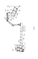
- Figure 9 shows a stacked container system 100 made up of the stackable containers according to the invention, comprising a number of stacked containers 10, 40, 50, 60, 70, 80, as discussed in the foregoing.
- the uniform dimensions of the containers which are adapted to fit one another, wherein a first linear dimension of the bottom wall is the same for all containers, and a second linear dimension of the bottom wall in a direction transversely to the first linear dimension is a whole multiple of the second linear dimension of a smallest container of the container system, makes it possible to stack the containers one on top of the other, contiguous to each other, so as to form a block-shaped stack of containers having substantially flat boundary walls or boundary surfaces 101, 102, 103. It will be understood that the stack of the container system 100 shown in figure 9 can be realised in various ways, for example with two containers 50 forming the lower part of the stack and two containers 10 and two containers 40 forming the upper part of the stack, etc.
- FIG. 9 which comprises stackable containers having a loading capacity of 3 m 3 , 6 m 3 and 9 m 3 , respectively, at most 36 m 3 bulk material or waste can be transported per truck with each run, whilst this is only at most 3 m 3 , 6 m 3 or 9 m 3 when a corresponding common skip is used.
- the stack fits the loading platform of a means of transport 110, such as a motorized means of transport in the form of a truck or a trailer 111 having dimensions that are permitted by law for such trucks and/or trailers, with a substantially flat, rectangular loading platform 112, 113 for placing and supporting containers according to the invention thereon.
- a means of transport 110 such as a motorized means of transport in the form of a truck or a trailer 111 having dimensions that are permitted by law for such trucks and/or trailers, with a substantially flat, rectangular loading platform 112, 113 for placing and supporting containers according to the invention thereon.
- wedge-shaped elements 114 extending in the direction away from the loading platform are provided on either side of the loading platform for receiving a container between the plate-shaped elements with its bottom wall.
- the wedge-shaped elements 114 are provided in spaced relationship in the longitudinal direction of the loading platform 112, 113. The wedge-shaped elements 114 secured the containers against displacement on the loading platform 112, 113.
- the wedge-shaped elements 114 taper off in the direction away from the loading platform for receiving a container between the inclined sides of opposite wedge-shaped elements 114.
- the wedge-shaped elements 114 may also be formed by wedge-shaped longitudinal sections or rails extending in the longitudinal direction of the loading platform on either side thereof.
- stanchions 115 are provided on either side of the loading platform for retaining stackable containers placed on the loading platform 112, 113 there between.
- the stanchions may be configured as folding stanchions fixed to the loading platform, or as detachable stanchions 115, for which purpose suitable receiving means 116 are disposed on the loading platform 112, 113.
- Such stanchions are known per se in practice. In figure 1 only one stanchion 115 is shown for the sake of clarity.
- Stanchions may also be provided at the short sides of the loading platform 112, 113, as is indicated by reference numeral 117.
- the embodiment shown in figure 9 comprises a partition 118, 119 disposed at each short side of the loading platform 112, against which the containers can be placed, so as to obtain a firm retainment of the stack of containers 100 on the loading platform 112 during road transport.
- the loading platform 113 is provided with a partition 120 at a short side.
- the means of transport 110 may furthermore be provided with a crane 130 disposed on the loading platform 112 at a short side thereof, which crane is provided with hoisting means 131 for moving a stackable container onto and off the loading platform 112.
- the crane is disposed on the loading platform 112 at the short side remote from the driver's cabin 121.
- the crane 130 can reach all the containers on the loading platforms 112 and 113 whilst the length of the hoisting arm thereof can remain within bounds.
- Figure 10 shows a container 10 being hoisted by means of the crane 130. Cables or chains 133 engage the crane hooks 31 on either side of the container 10 via a hoisting beam 132 for lifting the container 10 sideways or straddled there between.
- the container 10 is slightly inclined to the rear, i.e. the bottom wall 11 is positioned higher near the doors 26, 27 than near the side wall 14. In this position, the doors 26, 27 can be opened, whereupon the container 10 is subsequently pulled up via a cable or chain 135 driven by a winch 134, which engages the eye-shaped hook 32, such that the container 10 tilts forward for discharging the contents of the container 10 via the open doors 26, 27, as is shown in figure 11 .
- Figure 12 is a large-scale view of the hoisting beam 132 with the container 10, seen from the line XII-XII in figure 11 .
- the stackable containers can be moved onto or off the loading platform both from either side of the loading platform 112, 113 and from the front and the rear of the means of transport. This provides a high degree of flexibility, making it possible to place a stackable container at practically any location.
- the invention provides an entirely novel container system, by means of which any demand for waste transport and waste collection of bulk material and other similar waste can be met in an economic and environmentally responsible manner in practice while using a limited number of standardised containers.
Landscapes
- Engineering & Computer Science (AREA)
- Mechanical Engineering (AREA)
- Transportation (AREA)
- Stackable Containers (AREA)
Applications Claiming Priority (1)
| Application Number | Priority Date | Filing Date | Title |
|---|---|---|---|
| NL2004902A NL2004902C2 (nl) | 2010-06-16 | 2010-06-16 | Stapelbare container, containersysteem en transportmiddel voor stortgoed en andere soorten afval. |
Publications (3)
| Publication Number | Publication Date |
|---|---|
| EP2397423A2 true EP2397423A2 (fr) | 2011-12-21 |
| EP2397423A3 EP2397423A3 (fr) | 2012-03-07 |
| EP2397423B1 EP2397423B1 (fr) | 2015-12-30 |
Family
ID=43086469
Family Applications (1)
| Application Number | Title | Priority Date | Filing Date |
|---|---|---|---|
| EP11170234.6A Not-in-force EP2397423B1 (fr) | 2010-06-16 | 2011-06-16 | Système de conteneurs pour matériau en vrac |
Country Status (2)
| Country | Link |
|---|---|
| EP (1) | EP2397423B1 (fr) |
| NL (1) | NL2004902C2 (fr) |
Cited By (3)
| Publication number | Priority date | Publication date | Assignee | Title |
|---|---|---|---|---|
| ES2394341A1 (es) * | 2012-10-09 | 2013-01-30 | Jose Llinas E Hijos, S.L. | Contenedor intermodal de carga |
| RU2689926C2 (ru) * | 2016-07-25 | 2019-05-29 | Раис Хасанович Галеев | Автопоезд для перевозки грузов |
| FR3134569A1 (fr) * | 2022-04-14 | 2023-10-20 | Eiffage Fondations | Conteneur modulaire formant bac à déblais de chantier |
Citations (2)
| Publication number | Priority date | Publication date | Assignee | Title |
|---|---|---|---|---|
| DE9310355U1 (de) | 1993-01-22 | 1993-11-04 | Schenker Ind U Staedtereinigun | Bauschutt-/Wertstoff-Container |
| DE9314739U1 (de) | 1993-09-09 | 1994-02-03 | Bittner Gmbh & Co Kg A | Absetzmulde |
Family Cites Families (9)
| Publication number | Priority date | Publication date | Assignee | Title |
|---|---|---|---|---|
| US1407595A (en) * | 1921-04-28 | 1922-02-21 | Alfred H Smith | Lading container |
| FR2172844B3 (fr) * | 1972-02-24 | 1975-02-21 | Cie Gle Transatlantique | |
| DE3329744A1 (de) * | 1983-08-17 | 1985-03-07 | Graaff Kg, 3210 Elze | Grosscontainer |
| US4603787A (en) * | 1985-10-01 | 1986-08-05 | Larry Essary | Multi-use job box |
| DE9110046U1 (fr) * | 1991-08-14 | 1991-12-19 | Boes, Hans Christian, Dipl.-Ing., 4650 Gelsenkirchen, De | |
| FR2732314B1 (fr) * | 1995-03-28 | 1997-05-16 | Giat Ind Sa | Dispositif pour assemblage face contre face des conteneurs de transport |
| DE10053615A1 (de) * | 2000-10-28 | 2002-05-02 | Stephan Hase | Justiervorrichtung für aufeinander stapelbare Behälter insbesondere Container |
| JP2003312774A (ja) * | 2002-04-26 | 2003-11-06 | Nippon Sharyo Seizo Kaisha Ltd | 廃棄物用コンテナ |
| CN201023916Y (zh) * | 2007-02-12 | 2008-02-20 | 中国国际海运集装箱(集团)股份有限公司 | 一种垃圾运输箱 |
-
2010
- 2010-06-16 NL NL2004902A patent/NL2004902C2/nl not_active IP Right Cessation
-
2011
- 2011-06-16 EP EP11170234.6A patent/EP2397423B1/fr not_active Not-in-force
Patent Citations (2)
| Publication number | Priority date | Publication date | Assignee | Title |
|---|---|---|---|---|
| DE9310355U1 (de) | 1993-01-22 | 1993-11-04 | Schenker Ind U Staedtereinigun | Bauschutt-/Wertstoff-Container |
| DE9314739U1 (de) | 1993-09-09 | 1994-02-03 | Bittner Gmbh & Co Kg A | Absetzmulde |
Cited By (3)
| Publication number | Priority date | Publication date | Assignee | Title |
|---|---|---|---|---|
| ES2394341A1 (es) * | 2012-10-09 | 2013-01-30 | Jose Llinas E Hijos, S.L. | Contenedor intermodal de carga |
| RU2689926C2 (ru) * | 2016-07-25 | 2019-05-29 | Раис Хасанович Галеев | Автопоезд для перевозки грузов |
| FR3134569A1 (fr) * | 2022-04-14 | 2023-10-20 | Eiffage Fondations | Conteneur modulaire formant bac à déblais de chantier |
Also Published As
| Publication number | Publication date |
|---|---|
| EP2397423A3 (fr) | 2012-03-07 |
| NL2004902C2 (nl) | 2011-12-19 |
| EP2397423B1 (fr) | 2015-12-30 |
Similar Documents
| Publication | Publication Date | Title |
|---|---|---|
| SU1407393A3 (ru) | Контейнер,предназначенный дл транспортировки на железнодорожном вагоне | |
| US7524159B2 (en) | Method of receiving and transporting solid waste | |
| US7497347B2 (en) | Storage unit for being portable, towable, liftable, rackable, and weatherproof | |
| US5326212A (en) | Sectional van trailer having detachable, interchangeable compartments capable of forming a continuous van body | |
| US8545161B2 (en) | Unloading vehicle and combination of an unloading vehicle with a container | |
| US5192176A (en) | Sectional van trailer having detachable, interchangeable compartments capable of forming a continuous van body with accompanying system for forming shelf decks and partition walls within cargo holding sections | |
| WO2011096878A1 (fr) | Dispositif de manutention de conteneur, utilisation de ce dernier et procédés de déchargement et de chargement | |
| EP2233425B1 (fr) | Système pour décharger un conteneur d'un wagon. | |
| US4618068A (en) | Method and apparatus for shipping and storing cargo | |
| AU2010215087B2 (en) | Logistics panel and containers | |
| EP2397423B1 (fr) | Système de conteneurs pour matériau en vrac | |
| WO2011113995A1 (fr) | Contenant | |
| US5326213A (en) | Section van trailer having detachable and interchangeable compartments for transporting both household belongings and commercial freight | |
| AU713443B2 (en) | Nestable container for hauling materials | |
| EP0808780A1 (fr) | Dispositif conteneur pour le transport avec élévateur, en particulier pour l'expédition de véhicules automobiles | |
| US20090127256A1 (en) | Storage unit for being portable, towable, liftable, rackable, and weatherproof | |
| WO2011003414A1 (fr) | Conteneur logistique, tel qu'un conteneur d'expédition, et procédé pour charger et décharger celui-ci | |
| JPH09188188A (ja) | コンテナーバッグを搭載したコンテナー車両 | |
| WO2014017917A2 (fr) | Dispositif de transport de voitures et procédés de conditionnement de voitures à des fins de transport | |
| CA2667746A1 (fr) | Vehicule de dechargement et combinaison d'un conteneur et d'un vehicule de dechargement | |
| WO2009093893A1 (fr) | Conteneur de transport, procédé d'empilement de conteneurs et ensemble de conteneurs et de toits | |
| US20170080840A1 (en) | Combination Vehicle and Apparatus for Loading and Covering Material Located on a Vehicle Bed, Apparatus for Loading Material, and/or Method for Lifting Material | |
| RU2763623C1 (ru) | Транспортный контейнер для перевозки сыпучего или штучного груза | |
| US20110085879A1 (en) | Portable bin | |
| AU2001100372A4 (en) | Tipper trailer |
Legal Events
| Date | Code | Title | Description |
|---|---|---|---|
| AK | Designated contracting states |
Kind code of ref document: A2 Designated state(s): AL AT BE BG CH CY CZ DE DK EE ES FI FR GB GR HR HU IE IS IT LI LT LU LV MC MK MT NL NO PL PT RO RS SE SI SK SM TR |
|
| AX | Request for extension of the european patent |
Extension state: BA ME |
|
| PUAI | Public reference made under article 153(3) epc to a published international application that has entered the european phase |
Free format text: ORIGINAL CODE: 0009012 |
|
| PUAL | Search report despatched |
Free format text: ORIGINAL CODE: 0009013 |
|
| AK | Designated contracting states |
Kind code of ref document: A3 Designated state(s): AL AT BE BG CH CY CZ DE DK EE ES FI FR GB GR HR HU IE IS IT LI LT LU LV MC MK MT NL NO PL PT RO RS SE SI SK SM TR |
|
| AX | Request for extension of the european patent |
Extension state: BA ME |
|
| RIC1 | Information provided on ipc code assigned before grant |
Ipc: B65D 88/02 20060101AFI20120131BHEP Ipc: B65D 88/12 20060101ALI20120131BHEP Ipc: B65D 90/00 20060101ALI20120131BHEP |
|
| 17P | Request for examination filed |
Effective date: 20120907 |
|
| 17Q | First examination report despatched |
Effective date: 20130925 |
|
| RIC1 | Information provided on ipc code assigned before grant |
Ipc: B65D 88/12 20060101ALI20140923BHEP Ipc: B65D 88/02 20060101AFI20140923BHEP Ipc: B60P 1/34 20060101ALI20140923BHEP Ipc: B65D 90/00 20060101ALI20140923BHEP Ipc: B60P 1/54 20060101ALI20140923BHEP |
|
| GRAP | Despatch of communication of intention to grant a patent |
Free format text: ORIGINAL CODE: EPIDOSNIGR1 |
|
| INTG | Intention to grant announced |
Effective date: 20141030 |
|
| RIN1 | Information on inventor provided before grant (corrected) |
Inventor name: AANTJES, AART |
|
| GRAS | Grant fee paid |
Free format text: ORIGINAL CODE: EPIDOSNIGR3 |
|
| GRAA | (expected) grant |
Free format text: ORIGINAL CODE: 0009210 |
|
| AK | Designated contracting states |
Kind code of ref document: B1 Designated state(s): AL AT BE BG CH CY CZ DE DK EE ES FI FR GB GR HR HU IE IS IT LI LT LU LV MC MK MT NL NO PL PT RO RS SE SI SK SM TR |
|
| REG | Reference to a national code |
Ref country code: GB Ref legal event code: FG4D Ref country code: NL Ref legal event code: FP |
|
| REG | Reference to a national code |
Ref country code: CH Ref legal event code: EP |
|
| REG | Reference to a national code |
Ref country code: AT Ref legal event code: REF Ref document number: 767356 Country of ref document: AT Kind code of ref document: T Effective date: 20160115 |
|
| REG | Reference to a national code |
Ref country code: IE Ref legal event code: FG4D |
|
| REG | Reference to a national code |
Ref country code: DE Ref legal event code: R096 Ref document number: 602011022198 Country of ref document: DE |
|
| REG | Reference to a national code |
Ref country code: LT Ref legal event code: MG4D |
|
| PG25 | Lapsed in a contracting state [announced via postgrant information from national office to epo] |
Ref country code: HR Free format text: LAPSE BECAUSE OF FAILURE TO SUBMIT A TRANSLATION OF THE DESCRIPTION OR TO PAY THE FEE WITHIN THE PRESCRIBED TIME-LIMIT Effective date: 20151230 Ref country code: NO Free format text: LAPSE BECAUSE OF FAILURE TO SUBMIT A TRANSLATION OF THE DESCRIPTION OR TO PAY THE FEE WITHIN THE PRESCRIBED TIME-LIMIT Effective date: 20160330 Ref country code: LT Free format text: LAPSE BECAUSE OF FAILURE TO SUBMIT A TRANSLATION OF THE DESCRIPTION OR TO PAY THE FEE WITHIN THE PRESCRIBED TIME-LIMIT Effective date: 20151230 |
|
| REG | Reference to a national code |
Ref country code: AT Ref legal event code: MK05 Ref document number: 767356 Country of ref document: AT Kind code of ref document: T Effective date: 20151230 |
|
| PG25 | Lapsed in a contracting state [announced via postgrant information from national office to epo] |
Ref country code: GR Free format text: LAPSE BECAUSE OF FAILURE TO SUBMIT A TRANSLATION OF THE DESCRIPTION OR TO PAY THE FEE WITHIN THE PRESCRIBED TIME-LIMIT Effective date: 20160331 Ref country code: RS Free format text: LAPSE BECAUSE OF FAILURE TO SUBMIT A TRANSLATION OF THE DESCRIPTION OR TO PAY THE FEE WITHIN THE PRESCRIBED TIME-LIMIT Effective date: 20151230 Ref country code: FI Free format text: LAPSE BECAUSE OF FAILURE TO SUBMIT A TRANSLATION OF THE DESCRIPTION OR TO PAY THE FEE WITHIN THE PRESCRIBED TIME-LIMIT Effective date: 20151230 Ref country code: SE Free format text: LAPSE BECAUSE OF FAILURE TO SUBMIT A TRANSLATION OF THE DESCRIPTION OR TO PAY THE FEE WITHIN THE PRESCRIBED TIME-LIMIT Effective date: 20151230 Ref country code: LV Free format text: LAPSE BECAUSE OF FAILURE TO SUBMIT A TRANSLATION OF THE DESCRIPTION OR TO PAY THE FEE WITHIN THE PRESCRIBED TIME-LIMIT Effective date: 20151230 |
|
| PG25 | Lapsed in a contracting state [announced via postgrant information from national office to epo] |
Ref country code: ES Free format text: LAPSE BECAUSE OF FAILURE TO SUBMIT A TRANSLATION OF THE DESCRIPTION OR TO PAY THE FEE WITHIN THE PRESCRIBED TIME-LIMIT Effective date: 20151230 Ref country code: CZ Free format text: LAPSE BECAUSE OF FAILURE TO SUBMIT A TRANSLATION OF THE DESCRIPTION OR TO PAY THE FEE WITHIN THE PRESCRIBED TIME-LIMIT Effective date: 20151230 Ref country code: IT Free format text: LAPSE BECAUSE OF FAILURE TO SUBMIT A TRANSLATION OF THE DESCRIPTION OR TO PAY THE FEE WITHIN THE PRESCRIBED TIME-LIMIT Effective date: 20151230 |
|
| PG25 | Lapsed in a contracting state [announced via postgrant information from national office to epo] |
Ref country code: SK Free format text: LAPSE BECAUSE OF FAILURE TO SUBMIT A TRANSLATION OF THE DESCRIPTION OR TO PAY THE FEE WITHIN THE PRESCRIBED TIME-LIMIT Effective date: 20151230 Ref country code: IS Free format text: LAPSE BECAUSE OF FAILURE TO SUBMIT A TRANSLATION OF THE DESCRIPTION OR TO PAY THE FEE WITHIN THE PRESCRIBED TIME-LIMIT Effective date: 20160430 Ref country code: PT Free format text: LAPSE BECAUSE OF FAILURE TO SUBMIT A TRANSLATION OF THE DESCRIPTION OR TO PAY THE FEE WITHIN THE PRESCRIBED TIME-LIMIT Effective date: 20160502 Ref country code: SM Free format text: LAPSE BECAUSE OF FAILURE TO SUBMIT A TRANSLATION OF THE DESCRIPTION OR TO PAY THE FEE WITHIN THE PRESCRIBED TIME-LIMIT Effective date: 20151230 Ref country code: RO Free format text: LAPSE BECAUSE OF FAILURE TO SUBMIT A TRANSLATION OF THE DESCRIPTION OR TO PAY THE FEE WITHIN THE PRESCRIBED TIME-LIMIT Effective date: 20151230 Ref country code: PL Free format text: LAPSE BECAUSE OF FAILURE TO SUBMIT A TRANSLATION OF THE DESCRIPTION OR TO PAY THE FEE WITHIN THE PRESCRIBED TIME-LIMIT Effective date: 20151230 Ref country code: EE Free format text: LAPSE BECAUSE OF FAILURE TO SUBMIT A TRANSLATION OF THE DESCRIPTION OR TO PAY THE FEE WITHIN THE PRESCRIBED TIME-LIMIT Effective date: 20151230 Ref country code: AT Free format text: LAPSE BECAUSE OF FAILURE TO SUBMIT A TRANSLATION OF THE DESCRIPTION OR TO PAY THE FEE WITHIN THE PRESCRIBED TIME-LIMIT Effective date: 20151230 |
|
| REG | Reference to a national code |
Ref country code: DE Ref legal event code: R097 Ref document number: 602011022198 Country of ref document: DE |
|
| PG25 | Lapsed in a contracting state [announced via postgrant information from national office to epo] |
Ref country code: DK Free format text: LAPSE BECAUSE OF FAILURE TO SUBMIT A TRANSLATION OF THE DESCRIPTION OR TO PAY THE FEE WITHIN THE PRESCRIBED TIME-LIMIT Effective date: 20151230 |
|
| PLBE | No opposition filed within time limit |
Free format text: ORIGINAL CODE: 0009261 |
|
| STAA | Information on the status of an ep patent application or granted ep patent |
Free format text: STATUS: NO OPPOSITION FILED WITHIN TIME LIMIT |
|
| 26N | No opposition filed |
Effective date: 20161003 |
|
| PG25 | Lapsed in a contracting state [announced via postgrant information from national office to epo] |
Ref country code: BE Free format text: LAPSE BECAUSE OF NON-PAYMENT OF DUE FEES Effective date: 20160630 |
|
| REG | Reference to a national code |
Ref country code: DE Ref legal event code: R119 Ref document number: 602011022198 Country of ref document: DE |
|
| PG25 | Lapsed in a contracting state [announced via postgrant information from national office to epo] |
Ref country code: MC Free format text: LAPSE BECAUSE OF FAILURE TO SUBMIT A TRANSLATION OF THE DESCRIPTION OR TO PAY THE FEE WITHIN THE PRESCRIBED TIME-LIMIT Effective date: 20151230 |
|
| REG | Reference to a national code |
Ref country code: CH Ref legal event code: PL |
|
| REG | Reference to a national code |
Ref country code: NL Ref legal event code: MM Effective date: 20160701 |
|
| PG25 | Lapsed in a contracting state [announced via postgrant information from national office to epo] |
Ref country code: SI Free format text: LAPSE BECAUSE OF FAILURE TO SUBMIT A TRANSLATION OF THE DESCRIPTION OR TO PAY THE FEE WITHIN THE PRESCRIBED TIME-LIMIT Effective date: 20151230 |
|
| GBPC | Gb: european patent ceased through non-payment of renewal fee |
Effective date: 20160616 |
|
| REG | Reference to a national code |
Ref country code: IE Ref legal event code: MM4A |
|
| REG | Reference to a national code |
Ref country code: FR Ref legal event code: ST Effective date: 20170228 |
|
| PG25 | Lapsed in a contracting state [announced via postgrant information from national office to epo] |
Ref country code: CH Free format text: LAPSE BECAUSE OF NON-PAYMENT OF DUE FEES Effective date: 20160630 Ref country code: DE Free format text: LAPSE BECAUSE OF NON-PAYMENT OF DUE FEES Effective date: 20170103 Ref country code: LI Free format text: LAPSE BECAUSE OF NON-PAYMENT OF DUE FEES Effective date: 20160630 Ref country code: FR Free format text: LAPSE BECAUSE OF NON-PAYMENT OF DUE FEES Effective date: 20160630 |
|
| PG25 | Lapsed in a contracting state [announced via postgrant information from national office to epo] |
Ref country code: GB Free format text: LAPSE BECAUSE OF NON-PAYMENT OF DUE FEES Effective date: 20160616 Ref country code: NL Free format text: LAPSE BECAUSE OF NON-PAYMENT OF DUE FEES Effective date: 20160701 Ref country code: IE Free format text: LAPSE BECAUSE OF NON-PAYMENT OF DUE FEES Effective date: 20160616 |
|
| PG25 | Lapsed in a contracting state [announced via postgrant information from national office to epo] |
Ref country code: HU Free format text: LAPSE BECAUSE OF FAILURE TO SUBMIT A TRANSLATION OF THE DESCRIPTION OR TO PAY THE FEE WITHIN THE PRESCRIBED TIME-LIMIT; INVALID AB INITIO Effective date: 20110616 Ref country code: CY Free format text: LAPSE BECAUSE OF FAILURE TO SUBMIT A TRANSLATION OF THE DESCRIPTION OR TO PAY THE FEE WITHIN THE PRESCRIBED TIME-LIMIT Effective date: 20151230 |
|
| PG25 | Lapsed in a contracting state [announced via postgrant information from national office to epo] |
Ref country code: LU Free format text: LAPSE BECAUSE OF NON-PAYMENT OF DUE FEES Effective date: 20160616 Ref country code: TR Free format text: LAPSE BECAUSE OF FAILURE TO SUBMIT A TRANSLATION OF THE DESCRIPTION OR TO PAY THE FEE WITHIN THE PRESCRIBED TIME-LIMIT Effective date: 20151230 Ref country code: MK Free format text: LAPSE BECAUSE OF FAILURE TO SUBMIT A TRANSLATION OF THE DESCRIPTION OR TO PAY THE FEE WITHIN THE PRESCRIBED TIME-LIMIT Effective date: 20151230 Ref country code: MT Free format text: LAPSE BECAUSE OF NON-PAYMENT OF DUE FEES Effective date: 20160630 |
|
| PG25 | Lapsed in a contracting state [announced via postgrant information from national office to epo] |
Ref country code: BG Free format text: LAPSE BECAUSE OF FAILURE TO SUBMIT A TRANSLATION OF THE DESCRIPTION OR TO PAY THE FEE WITHIN THE PRESCRIBED TIME-LIMIT Effective date: 20151230 |
|
| PG25 | Lapsed in a contracting state [announced via postgrant information from national office to epo] |
Ref country code: AL Free format text: LAPSE BECAUSE OF FAILURE TO SUBMIT A TRANSLATION OF THE DESCRIPTION OR TO PAY THE FEE WITHIN THE PRESCRIBED TIME-LIMIT Effective date: 20151230 |