EP0081220B1 - Laufrolle für Apparate, Möbel od. dgl. - Google Patents
Laufrolle für Apparate, Möbel od. dgl. Download PDFInfo
- Publication number
- EP0081220B1 EP0081220B1 EP82111244A EP82111244A EP0081220B1 EP 0081220 B1 EP0081220 B1 EP 0081220B1 EP 82111244 A EP82111244 A EP 82111244A EP 82111244 A EP82111244 A EP 82111244A EP 0081220 B1 EP0081220 B1 EP 0081220B1
- Authority
- EP
- European Patent Office
- Prior art keywords
- recesses
- tire
- tyre
- rim
- flanges
- Prior art date
- Legal status (The legal status is an assumption and is not a legal conclusion. Google has not performed a legal analysis and makes no representation as to the accuracy of the status listed.)
- Expired
Links
- 238000005299 abrasion Methods 0.000 claims description 7
- 239000004814 polyurethane Substances 0.000 claims description 6
- 229920001971 elastomer Polymers 0.000 claims description 5
- 239000000806 elastomer Substances 0.000 claims description 5
- 230000002093 peripheral effect Effects 0.000 claims description 5
- 239000000463 material Substances 0.000 claims description 4
- 239000000725 suspension Substances 0.000 description 4
- 230000006835 compression Effects 0.000 description 3
- 238000007906 compression Methods 0.000 description 3
- 239000000356 contaminant Substances 0.000 description 2
- 238000013016 damping Methods 0.000 description 2
- JOYRKODLDBILNP-UHFFFAOYSA-N Ethyl urethane Chemical compound CCOC(N)=O JOYRKODLDBILNP-UHFFFAOYSA-N 0.000 description 1
- 230000015572 biosynthetic process Effects 0.000 description 1
- 239000000428 dust Substances 0.000 description 1
- 230000000694 effects Effects 0.000 description 1
- 230000002349 favourable effect Effects 0.000 description 1
- 230000001771 impaired effect Effects 0.000 description 1
- 230000009191 jumping Effects 0.000 description 1
- 239000002184 metal Substances 0.000 description 1
- 239000002245 particle Substances 0.000 description 1
- -1 pebbles Substances 0.000 description 1
- 230000000149 penetrating effect Effects 0.000 description 1
Images
Classifications
-
- B—PERFORMING OPERATIONS; TRANSPORTING
- B60—VEHICLES IN GENERAL
- B60C—VEHICLE TYRES; TYRE INFLATION; TYRE CHANGING; CONNECTING VALVES TO INFLATABLE ELASTIC BODIES IN GENERAL; DEVICES OR ARRANGEMENTS RELATED TO TYRES
- B60C7/00—Non-inflatable or solid tyres
- B60C7/10—Non-inflatable or solid tyres characterised by means for increasing resiliency
- B60C7/12—Non-inflatable or solid tyres characterised by means for increasing resiliency using enclosed chambers, e.g. gas-filled
- B60C7/121—Non-inflatable or solid tyres characterised by means for increasing resiliency using enclosed chambers, e.g. gas-filled enclosed chambers defined by a distinct core
-
- B—PERFORMING OPERATIONS; TRANSPORTING
- B60—VEHICLES IN GENERAL
- B60B—VEHICLE WHEELS; CASTORS; AXLES FOR WHEELS OR CASTORS; INCREASING WHEEL ADHESION
- B60B9/00—Wheels of high resiliency, e.g. with conical interacting pressure-surfaces
- B60B9/02—Wheels of high resiliency, e.g. with conical interacting pressure-surfaces using springs resiliently mounted bicycle rims
- B60B9/10—Wheels of high resiliency, e.g. with conical interacting pressure-surfaces using springs resiliently mounted bicycle rims of rubber or the like
Definitions
- the invention relates to a roller for apparatus, furniture or the like. With at least one tire mounted on a wheel rim, which is penetrated by a multiplicity of recesses parallel to the wheel axis, the walls of which are possibly brought close to the inner surface of the tire.
- Such rollers are used as vehicle wheels, in particular automobile wheels e.g. known from FR-A-1 278 131. Specifically, these are apparently metallic wheels in the manner of spoke wheels, in which the spaces between the spokes form the aforementioned recesses parallel to the radach. According to a version of FR-A-1 278131, the spokes are made in one piece with the wheel rim and the rim.
- the invention is essentially based on the object of developing a roller of the known type in a manner which is particularly suitable for use on apparatus, furniture or the like, in particular to provide a roller whose tires have excellent wear properties and a favorable elasticity behavior with little material expenditure.
- Another aspect of the invention is to embed the tire in the rim in such a way that it is particularly secured against jumping off and inadmissible deformations.
- the invention solves this problem on the one hand in that the tire is made of a highly abrasion-resistant elastomer such as polyurethane (PU) and the recesses are provided exclusively within its section arranged in the peripheral region of the rim flanges and on the other hand with an alternative embodiment in that the tire is made of a highly abrasion-resistant Elastomer such as polyurethane (PU) is made and the recesses, the walls of which are part of the inner surface of the tire, are provided exclusively within its section arranged in the peripheral region of the rim flanges.
- PU polyurethane
- the rim flanges Due to the tight assignment of the recesses to the inner surface of the tire, effective transverse expansion and thus transverse forces are reduced to a minimum when the tire is compressed, so that the rim flanges are not or only very slightly loaded by lateral forces. Due to the side shielding of the perforated tire area, the rim flanges serve as lateral supports in the deformation area of the tire, so that a targeted deformation of the webs remaining between the recesses is brought about in the sense of the desired elasticity behavior.
- DE-B-1 806 146 in principle proposes a wheel with a tire made elastic by means of recesses, but whose wear resistance is brought about by a special tread laid around the outside of the tire.
- the object of the present invention aims to use a thin tire which is itself highly abrasion-resistant and in which the recesses or the webs are arranged between them in such a way that asymmetrical tire loading is avoided and which, moreover, is fully functional even when the tire is used for a long time stay.
- the configuration of the tire known from DE-B-1 806 146 is suitable for storage in a rim well in such a way that the rim flanges cover the outer openings of the recesses, because then a run on the circumference of the tire due to the compression of the tire Rim flanges would be inevitable.
- the wall thickness measured in the radial direction of the tire section lying between the rim flanges is greater than or at most equal to half of the total tire wall thickness.
- the webs arranged between two recesses can either be arranged essentially radially or alternately at approximately equal inclination angles in different directions with respect to the radial. This always results in an essentially radially acting tire compression in the area of the tire contact area and a minimization of the flexing work.
- An elastomeric tire material that has a hardness of approximately 80 to 90 Shore has proven to be advantageous.
- a sprayable polyurethane (PU) has particularly excellent properties.
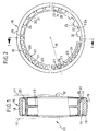
- the 1 comprises a wheel fork, the fork legs of which are designated 11.
- the fork legs 11 support a wheel axle 12 on which the wheel rim 13 can rotate freely.
- the wheel rim 13 has a rim bed 15 arranged between two rim flanges 14, in which a tire 16 rests.
- the annular tire 16 consists of an inner section 17 and an outer section 18.
- the width (FIG. 1) of the inner section 17 corresponds approximately to the clear width of the rim base 15 between the rim flanges 14, while the wider outer section is designed here that the outer width of the tire section 18 corresponds to the outer rim width in the area of the rim flanges 14.
- the tire therefore has an approximately T-shaped cross section.
- the outer section 18 is smooth, the tread 19 - as shown in FIG. 1 - slightly spherical.
- the tire also consists of a highly abrasion-resistant polyurethane (PU) with a hardness of preferably about 80 to 90 Shore.
- PU highly abrasion-resistant polyurethane
- this tire has - and only within the inner section 17 - a plurality of circumferentially evenly spaced recesses, for example circular (20), triangular (21), rectangular (23) or bean-shaped (24) can be designed as self-contained openings or which, like the recesses 22, can be designed to be open inwards in such a way that the wall region 22a of a recess 22 is a surface component of the inner surface 25 of the tire.
- a plurality of circumferentially evenly spaced recesses for example circular (20), triangular (21), rectangular (23) or bean-shaped (24) can be designed as self-contained openings or which, like the recesses 22, can be designed to be open inwards in such a way that the wall region 22a of a recess 22 is a surface component of the inner surface 25 of the tire.
- the webs 26 to 29 should be made relatively thin.
- the ring web 30 remaining between the recesses and the inner surface 25 should also be thin.
- the recesses (here 20 and 22) are located entirely within the rim bed 15 delimited by the rim flanges 14. It is therefore impossible for contaminants, pebbles, dust or anything else to penetrate the recesses which completely penetrate the tire in the inner section 18 Particles enter and reduce or cancel the tire's suspension properties. This ensures that the wheel arch is always flawless and, above all, even.
- the webs are not arranged essentially radially, as here the webs 27 and 28, they run alternately at approximately the same angle of inclination in different directions with respect to the radial R, which also ensures a substantially purely radial, at least symmetrical deflection of the tire.
- the spring effect in the recesses 22 is achieved by evading the relatively thick webs 31 in the circumferential direction during the tire compression.
Landscapes
- Engineering & Computer Science (AREA)
- Mechanical Engineering (AREA)
- Tires In General (AREA)
- Rollers For Roller Conveyors For Transfer (AREA)
Description
- Die Erfindung bezieht sich auf eine Laufrolle für Apparate, Möbel od. dgl. mit mindestens einem auf einer Radfelge aufgezogenen Reifen, der von einer Vielzahl von radachsparallelen Ausnehmungen durchsetzt ist, deren Wände ggf. bis nahe an die Reifen-Innenfläche herangeführt sind.
- Derartige Laufrollen sind als Fahrzeugräder, indbesondere Automobilräder z.B. aus der FR-A-1 278 131 bekannt. Hierbei handelt es sich konkret offenbar um metallische Räder nach Art von Speichenrädern, bei denen die Zwischenräume zwischen den Speichen die genannten radachsparallelen Ausnehmungen bilden. Nach einer Ausführung der FR-A-1 278131 sind die Speichen mit dem Radkranz und der Felge einstückig ausgeführt.
- Der Erfindung liegt im wesentlichen die Aufgabe zugrunde, eine Laufrolle der bekannten Art in einer zur Verwendung an Apparaten, Möbel od. dgl. besonders geeigneten Weise weiterzubilden, insbesondere eine Laufrolle zu schaffen, deren Reifen unter geringem Werkstoffaufwand hervorragende Verschleisseigenschaften und ein günstiges Elastizitätsverhalten aufweist. Ein weiterer Aspekt der Erfindung besteht darin, den Reifen so in die Felge einzubetten, dass er darin gegen Abspringen und unzulässige Verformungen besonders gesichert ist.
- Die Erfindung löst diese Aufgabe einmal dadurch, dass der Reifen aus einem hochabriebfesten Elastomer wie Polyurethan (PU) besteht und die Ausnehmungen ausschliesslich innerhalb seines im Umfangsbereich der Felgenhörner angeordneten Abschnitts vorgesehen sind und zum anderen mit einer alternativen Ausführung dadurch, dass der Reifen aus einem hochabriebfesten Elastomer wie Polyurethan (PU) besteht und die Ausnehmungen, deren Wände Bestandteil der Reifen-Innenfläche sind, ausschliesslich innerhalb seines im Umfangsbereich der Felgenhörner angeordneten Abschnitts vorgesehen sind.
- Aufgrund des hochabriebfesten Elastomers des Reifens wird in Verbindung mit den ihn radachsparallel durchsetzenden Ausnehmungen ein relativ dünner, aber trotz seines geringen Werkstoffaufwandes hervorragende Federungseigenschaften aufweisender Reifen zur Verfügung gestellt. Dadurch, dass die Ausnehmungen ausschliesslich innerhalb des Umfangsbereichs der Felgenhörner angeordnet sind, wird gewährleistet, dass in die Ausnehmungen kein Schmutz und sonstige Verunreinigungen eintreten können. Damit ist auch sichergestellt, dass sich die Ausnehmungen nicht in einer solchen Weise zusetzen können, dass die Federungseigenschaften des Reifens beeinträchtigt werden oder nicht mehr gewährleistet sind. Durch die dichte Zuordnung der Ausnehmungen zur Reifen-Innenfläche werden bei der Kompression des Reifens wirksame Querausdehnungen und damit Querkräfte auf ein Minimum reduziert, so dass die Felgenhörner durch seitliche Kräfte nicht oder nur sehr wenig belastet sind. Durch die seitliche Abschirmung des durchlochten Reifenbereichs dienen die Felgenhörner als seitliche Stützen im Verformungsbereich des Reifens, so dass eine gezielte Verformung der zwischen den Ausnehmungen verbleibenden Stege im Sinne des gewünschten Elastizitätsverhaltens hervorgerufen wird.
- Aus der DE-B-1 806 146 ist es zwar an sich bekannt, einen aus Urethan bestehenden Rollenkörper zu verwenden und seine Feder- und Dämpfungswirkung durch im Rollenkörper angebrachte Ausnehmungen zu beeinflussen. Dieser bekannte Rollenkörper (Reifen) ist jedoch nicht in eine Felge eingebettet, sondern auf eine bund- bzw. hornlose Metallhülse aufgezogen. Die Ausnehmungen erstrecken sich nach aussen hin völlig offen in einem mittleren Bereich des in radialer Richtung sehr breiten Reifenringes. Auch durchsetzen die Ausnehmungen den Reifen nicht; die von beiden Stirnseiten des Reifens eingebrachten Ausnehmungen münden an einem mittleren Stegbereich. Im übrigen ist der Reifen dazu bestimmt, auf der Aussenseite noch mit einer Laufdecke versehen zu werden, um die Standfestigkeit zu erhöhen. Schliesslich verlaufen sämtliche zwischen den Ausnehmungen belassenen Stege in der Seitenansicht des Reifens (Fig. 5 der DE-B-1 806 146) jeweils zur gleichen Seite hin geneigt. Daher ist bei Belastung des Reifens dessen Verformung einseitig, was zu starken asymmetrischen Reifenverformungen und hohen Walkarbeiten führen kann.
- Die DE-B-1 806 146 schlägt im Prinzip ein Rad mit einem durch Ausnehmungen elastisch gemachten Reifen vor, dessen Verschleissfestigkeit aber durch eine besondere aussen um den Reifen herumgelegte Laufdecke bewirkt wird. Der Gegenstand vorliegender Erfindung zielt darauf ab, einen dünnen Reifen zu verwenden, der selbst hochabriebfest ist und bei dem die Ausnehmungen bzw. die Stege zwischen diesen so angeordnet sind, dass eine asymmetrische Reifenbelastung vermieden wird und die überdies auch bei längerem Gebrauch des Reifens voll funktionsfähig bleiben. Die Konfiguration des aus der DE-B-1 806 146 bekannten Reifens eignet sich wie der erfindungsgemässe Reifen zur Einlagerung in ein Felgenbett dergestalt, dass die Felgenhörner die äusseren Öffnungen der Ausnehmungen abdecken, weil dann wegen der Kompression des Radreifens ein Lauf auf dem Umfang der Felgenhörner unvermeidbar wäre.
- Eine Weiterbildung des im Anspruch 1 gekennzeichneten Erfindungsgegenstandes besteht darin, dass die in radialer Richtung gemessene Wandstärke des zwischen den Felgenhörnern liegenden Reifenabschnittes grösser oder höchstens gleich der Hälfte der gesamten Reifenwandstärke ist. Damit wird eine Laufrolle bereitgestellt, bei der ein grosser Reifenquerschnitt, der jedoch völlig im Felgenbett liegt, für die Federung und Dämpfung bereitgestellt wird, während der die äussere Lauffläche aufweisende Reifenabschnitt relativ dünn ist, wodurch der Rolle im übrigen ein hervorragendes äusseres Erscheinungsbild verliehen werden kann. Ausserdem wird durch diese Geometrie ein besonders sicherer Sitz des Reifens im Felgenbett erzielt.
- Die zwischen je zwei Ausnehmungen angeordneten Stege können entweder im wesentlichen radial oder alternierend unter etwa gleich grossen Neigungswinkeln unterschiedlicher Richtung bezüglich der Radialen angeordnet sein. Hierdurch ergibt sich stets eine im wesentlichen radial wirkende Reifenkompression im Bereich der Reifenaufstandszone und eine Minimierung der Walkverlustarbeit.
- Als vorteilhaft hat sich ein elastomerer Reifenwerkstoff erwiesen, der eine Härte von etwa 80 vis 90 Shore besitzt. Besonders hervorragende Eigenschaften hat ein spritzfähiges Polyurethan (PU).
- Die Erfindung wird nachfolgend anhand eines in den Zeichnungen dargestellten Ausführungsbeispiels näher beschrieben. Es zeigen:
- Fig. 1 einen Längsschnitt gemäss Schnittlinie I-I in Fig. 2 und
- Fig. 2 die Ansicht eines Laufreifens, wobei eine Auswahl von Möglichkeiten der Ausbildung der Ausnehmungen dargestellt ist.
- Ein insgesamt mit 10 bezeichnetes Laufrad nach Fig. 1 umfasst eine Radgabel, deren Gabelschenkel mit 11 bezeichnet sind. Die Gabelschenkel 11 lagern eine Radachse 12, auf der die Radfelge 13 frei rotieren kann. Die Radfelge 13 besitzt ein zwischen zwei Felgenhörnern 14 angeordnetes Felgenbett 15, in welchem ein Reifen 16 ruht.
- Der kreisringförmige Reifen 16 besteht aus einem inneren Abschnitt 17 und einem äusseren Abschnitt 18. Die Breite (Fig. 1) des inneren Abschnittes 17 entspricht etwa der lichten Weite des Felgenbettes 15 zwischen den Felgenhörnern 14, während der breitere äussere Abschnitt hier so gestaltet ist, dass die äussere Breite des Reifenabschnitts 18 der äusseren Felgenbreite im Bereich der Felgenhörner 14 entspricht. Im Längsschnitt nach Fig. 1 hat der Reifen daher einen etwa T-förmigen Querschnitt. Der äussere Abschnitt 18 ist glattflächig, die Lauffläche 19 - wie aus Fig. 1 ersichtlich - leicht ballig. Im übrigen besteht der Reifen aus einem hochabriebfesten Polyurethan (PU) mit einer Härte von vorzugsweise etwa 80 bis 90 Shore.
- Um diesen Reifen in besonderer Weise elastisch zu gestalten, besitzt er - und zwar ausschliesslich innerhalb des inneren Abschnittes 17 - eine Vielzahl von in Umfangsrichtung in gleichmässigen Abständen angeordneten Ausnehmungen, die beispielsweise kreisförmig (20), dreieckförmig (21), rechteckförmig (23) oder bohnenförmig (24) als in sich geschlossen umrandete Öffnungen ausgeführt sein können oder die, wie die Ausnehmungen 22, nach innen derart geöffnet ausgebildet sein können, dass der Wandbereich 22a einer Ausnehmung 22 Flächenbestandteil der Innenfläche 25 des Reifens ist.
- Insbesondere bei denjenigen Ausführungen, bei denen die Ausnehmungen 20, 21, 23 und 24 mit einer in sich geschlossenen inneren Umfangsfläche versehen sind, sollten die Stege 26 bis 29 relativ dünn ausgeführt sein. Ebenfalls dünn sollte der zwischen den Ausnehmungen und der Innenfläche 25 verbleibende Ringsteg 30 sein.
- Wie aus Fig. 1 ersichtlich, befinden sich die Ausnehmungen (hier 20 und 22) vollständig innerhalb des von den Felgenhörnern 14 begrenzten Felgenbettes 15. Es können daher in die den Reifen im inneren Abschnitt 18 vollständig durchsetzenden Ausnehmungen keine Verunreinigungen, Steinchen, Staub oder sonstige Partikel eintreten und die Federungseigenschaften des Reifens mindern oder aufheben. Damit ist zugleich ein stets einwandfreier und vor allem auch gleichmässiger Radlauf gewährleistet.
- Sofern die Stege nicht im wesentlichen radial angeordnet sind, wie hier die Stege 27 und 28, so verlaufen diese alternierend unter etwa gleich grossen Neigungswinkeln unterschiedlicher Richtung bezüglich der Radialen R, wodurch ebenfalls eine im wesentlichen rein radiale, jedenfalls symmetrische Einfederung des Reifens gewährleistet bleibt.
- Die Federwirkung bei den Ausnehmungen 22 wird durch ein Ausweichen der hier relativ dicken Stege 31 in Umfangsrichtung während der Reifenkompression erreicht.
Claims (6)
Priority Applications (1)
| Application Number | Priority Date | Filing Date | Title |
|---|---|---|---|
| AT82111244T ATE18023T1 (de) | 1981-12-07 | 1982-12-04 | Laufrolle fuer apparate, moebel od. dgl. |
Applications Claiming Priority (2)
| Application Number | Priority Date | Filing Date | Title |
|---|---|---|---|
| DE3148313A DE3148313C2 (de) | 1981-12-07 | 1981-12-07 | Laufrolle für Apparate, Möbel od. dgl. |
| DE3148313 | 1981-12-07 |
Publications (2)
| Publication Number | Publication Date |
|---|---|
| EP0081220A1 EP0081220A1 (de) | 1983-06-15 |
| EP0081220B1 true EP0081220B1 (de) | 1986-02-19 |
Family
ID=6148055
Family Applications (1)
| Application Number | Title | Priority Date | Filing Date |
|---|---|---|---|
| EP82111244A Expired EP0081220B1 (de) | 1981-12-07 | 1982-12-04 | Laufrolle für Apparate, Möbel od. dgl. |
Country Status (4)
| Country | Link |
|---|---|
| US (1) | US4549592A (de) |
| EP (1) | EP0081220B1 (de) |
| AT (1) | ATE18023T1 (de) |
| DE (1) | DE3148313C2 (de) |
Families Citing this family (26)
| Publication number | Priority date | Publication date | Assignee | Title |
|---|---|---|---|---|
| AU580294B2 (en) * | 1984-04-16 | 1989-01-12 | Uniroyal Goodrich Licensing Services, Inc. | Non-pneumatic tire with supporting and cushioning members |
| US4969548A (en) * | 1988-04-27 | 1990-11-13 | Kornylak Corporation | Compression set limiting gravity conveyor |
| GB8827337D0 (en) * | 1988-11-23 | 1988-12-29 | Medical Res Council | Nucleoside analogues |
| US4944563A (en) * | 1989-03-30 | 1990-07-31 | The Boeing Company | Wheel assembly including a solid tire |
| DE3912766A1 (de) * | 1989-04-19 | 1990-10-25 | Stein & Co Paul Vom | Laufrolle fuer apparate, moebel od. dgl. |
| CA2043082A1 (en) * | 1991-02-27 | 1992-08-28 | James Edward Duddey | Non-pneumatic spare tire |
| GB2303591A (en) * | 1995-07-27 | 1997-02-26 | Richard Martin Weatherley | Tyre for radio controlled model cars |
| US6681822B2 (en) * | 2002-04-26 | 2004-01-27 | The Goodyear Tire & Rubber Company | Non-pneumatic spare tire |
| JP4097576B2 (ja) * | 2003-07-18 | 2008-06-11 | ゴムノイナキ株式会社 | コンベアにおけるフリクションローラ |
| JP3808858B2 (ja) * | 2003-10-07 | 2006-08-16 | 住友ゴム工業株式会社 | サポートリング、及びタイヤ組立体 |
| US7143797B2 (en) * | 2005-01-04 | 2006-12-05 | Frederick F. Vannan | Airless tire |
| US8104524B2 (en) | 2007-03-27 | 2012-01-31 | Resilient Technologies Llc | Tension-based non-pneumatic tire |
| US8109308B2 (en) | 2007-03-27 | 2012-02-07 | Resilient Technologies LLC. | Tension-based non-pneumatic tire |
| US9108470B2 (en) | 2008-09-29 | 2015-08-18 | Polaris Industries Inc. | Run-flat device |
| US8281883B2 (en) * | 2008-11-11 | 2012-10-09 | Adalberto Prinz | Method and apparatus for transporting construction equipment in an enclosed container within the hold of a vessel |
| US8944125B2 (en) | 2009-07-20 | 2015-02-03 | Polaris Industries Inc. | Tension-based non-pneumatic tire |
| US8176957B2 (en) | 2009-07-20 | 2012-05-15 | Resilient Technologies, Llc. | Tension-based non-pneumatic tire |
| US9662939B2 (en) | 2009-07-28 | 2017-05-30 | Bridgestone Americas Tire Operations, Llc | Tension-based non-pneumatic tire |
| US9573422B2 (en) | 2012-03-15 | 2017-02-21 | Polaris Industries Inc. | Non-pneumatic tire |
| US9266506B2 (en) | 2012-04-25 | 2016-02-23 | Lindsay Corporation | Wheel and tire assembly with adjustable spacer system |
| US9090121B2 (en) | 2012-04-25 | 2015-07-28 | Lindsey Corporation | Wheel and tire assembly |
| US9302539B2 (en) | 2012-04-25 | 2016-04-05 | Lindsay Corporation | Wheel and tire assembly |
| US9242510B2 (en) | 2012-09-24 | 2016-01-26 | Lindsay Corporation | Wheel and tire assembly and method of assembly |
| US9186934B2 (en) | 2012-09-24 | 2015-11-17 | Lindsay Corporation | Wheel and tire assembly |
| JP6169407B2 (ja) * | 2013-05-01 | 2017-07-26 | コンビ株式会社 | 乳母車用の車輪および乳母車 |
| PL423490A1 (pl) * | 2017-11-17 | 2019-05-20 | Korzekwa Anita Przed Produkcyjno Handlowe Anitex | Opona koła wózka dziecięcego |
Family Cites Families (11)
| Publication number | Priority date | Publication date | Assignee | Title |
|---|---|---|---|---|
| DE65474C (de) * | R. JEWELL in City of London, 1S1 Queen Victoria Street | Versteifungs- und Triebspeichen bei Fahrrädern mit federnden Speichen | ||
| US2603267A (en) * | 1952-07-15 | Resilient wheel | ||
| DE66733C (de) * | J. B. DUNLOP, Thierarzt, in Belfast, Grafschaft Antrim, Irland | Federndes Rad für Fahrräder und Fahrzeuge | ||
| US1258573A (en) * | 1917-04-06 | 1918-03-05 | Samuel Johnstone | Automobile cushion-wheel. |
| US1447365A (en) * | 1921-03-24 | 1923-03-06 | Walther George | Cushion wheel |
| US1921548A (en) * | 1932-03-09 | 1933-08-08 | Charles A Dana | Juvenile tiring |
| FR898303A (fr) * | 1943-09-27 | 1945-04-19 | Jante élastique de remplacement pour roue de véhicule | |
| FR1278131A (fr) * | 1960-10-27 | 1961-12-08 | Roue pour véhicule notamment pour véhicules automobiles et procédés pour l'obtention de ladite roue | |
| US3514829A (en) * | 1968-06-27 | 1970-06-02 | Leland F Blatt | Rollers |
| BE759648A (fr) * | 1970-02-16 | 1971-04-30 | Kornylac Co | Transporteur automoteur avec des galets a bandages elastomeres en matiere a forte hysteresis |
| US4127166A (en) * | 1976-12-27 | 1978-11-28 | Wyman Ransome J | Non-pneumatic bicycle tire |
-
1981
- 1981-12-07 DE DE3148313A patent/DE3148313C2/de not_active Expired
-
1982
- 1982-12-04 AT AT82111244T patent/ATE18023T1/de not_active IP Right Cessation
- 1982-12-04 EP EP82111244A patent/EP0081220B1/de not_active Expired
- 1982-12-06 US US06/446,973 patent/US4549592A/en not_active Expired - Fee Related
Also Published As
| Publication number | Publication date |
|---|---|
| DE3148313C2 (de) | 1983-11-03 |
| DE3148313A1 (de) | 1983-06-23 |
| ATE18023T1 (de) | 1986-03-15 |
| EP0081220A1 (de) | 1983-06-15 |
| US4549592A (en) | 1985-10-29 |
Similar Documents
| Publication | Publication Date | Title |
|---|---|---|
| EP0081220A1 (de) | Laufrolle für Apparate, Möbel od. dgl. | |
| DE2537055A1 (de) | Sicherheitstrageinrichtung fuer die radfelge eines pneumatischen reifens | |
| DE19816327A1 (de) | Seilrolle | |
| DE2347446C2 (de) | Elastische Lagerung | |
| EP1277637B1 (de) | Rolle für ein Laufwerk bzw. für eine Rollenbatterie | |
| DE2105937A1 (de) | Schwerkraftförderer mit in Abstanden auf einanderfolgenden Rollen mit starrer Nabe und diese umschließendem Reifenkorper aus ela stomerem Polyurethan | |
| EP0379672A1 (de) | Ackerwalze | |
| DE69107258T2 (de) | Luftreifen mit doppelter Lauffläche. | |
| DE3507046C2 (de) | ||
| DE2321345C3 (de) | Radfelge für schlauchlose Reifen | |
| DE4430342C2 (de) | Gummigefedertes Schienenrad | |
| DE69101892T2 (de) | Stossdämpferkolben. | |
| DE9205660U1 (de) | Bodenwalze | |
| DE8135558U1 (de) | Laufrolle fuer apparate, moebel o.dgl. | |
| DE4407828A1 (de) | Walze, insbesondere für Textilbehandlungsmaschinen | |
| DE69118534T2 (de) | Boden eingreifende profilelemente | |
| DE2302665A1 (de) | Rolle fuer rollenfoerderbahnen | |
| DE3710104A1 (de) | Raupenkettenrolle | |
| EP0061136A1 (de) | Vorrichtung zur Überbrückung des gegenseitigen Abstands einander benachbarter Reifen | |
| DE4104457C2 (de) | Vollreifen | |
| DE1286422B (de) | Reifenfelge | |
| DE2817394A1 (de) | Stuetzteil fuer die laufdecke eines fahrzeugreifens | |
| EP3497349B1 (de) | Luftfederbalg mit selbstreinigender oberfläche | |
| DE20020990U1 (de) | Rohrleitungsmolch | |
| DE2530793C3 (de) | Gebremste Laufrolle für Sitzmöbel |
Legal Events
| Date | Code | Title | Description |
|---|---|---|---|
| PUAI | Public reference made under article 153(3) epc to a published international application that has entered the european phase |
Free format text: ORIGINAL CODE: 0009012 |
|
| AK | Designated contracting states |
Designated state(s): AT BE CH DE FR GB IT LI LU NL SE |
|
| RAP1 | Party data changed (applicant data changed or rights of an application transferred) |
Owner name: PAUL VOM STEIN & CO. |
|
| 17P | Request for examination filed |
Effective date: 19831213 |
|
| RBV | Designated contracting states (corrected) |
Designated state(s): AT BE CH FR GB IT LI LU NL SE |
|
| ITF | It: translation for a ep patent filed | ||
| GRAA | (expected) grant |
Free format text: ORIGINAL CODE: 0009210 |
|
| AK | Designated contracting states |
Designated state(s): AT BE CH FR GB IT LI LU NL SE |
|
| REF | Corresponds to: |
Ref document number: 18023 Country of ref document: AT Date of ref document: 19860315 Kind code of ref document: T |
|
| ET | Fr: translation filed | ||
| PG25 | Lapsed in a contracting state [announced via postgrant information from national office to epo] |
Ref country code: AT Effective date: 19861204 |
|
| PG25 | Lapsed in a contracting state [announced via postgrant information from national office to epo] |
Ref country code: SE Effective date: 19861205 |
|
| PLBE | No opposition filed within time limit |
Free format text: ORIGINAL CODE: 0009261 |
|
| STAA | Information on the status of an ep patent application or granted ep patent |
Free format text: STATUS: NO OPPOSITION FILED WITHIN TIME LIMIT |
|
| PG25 | Lapsed in a contracting state [announced via postgrant information from national office to epo] |
Ref country code: LU Free format text: LAPSE BECAUSE OF NON-PAYMENT OF DUE FEES Effective date: 19861231 Ref country code: BE Effective date: 19861231 |
|
| 26N | No opposition filed | ||
| BERE | Be: lapsed |
Owner name: PAUL VOM STEIN & CO. Effective date: 19861231 |
|
| PG25 | Lapsed in a contracting state [announced via postgrant information from national office to epo] |
Ref country code: LI Effective date: 19871231 Ref country code: CH Effective date: 19871231 |
|
| GBPC | Gb: european patent ceased through non-payment of renewal fee | ||
| REG | Reference to a national code |
Ref country code: CH Ref legal event code: PL |
|
| PG25 | Lapsed in a contracting state [announced via postgrant information from national office to epo] |
Ref country code: GB Free format text: LAPSE BECAUSE OF NON-PAYMENT OF DUE FEES Effective date: 19881122 |
|
| PGFP | Annual fee paid to national office [announced via postgrant information from national office to epo] |
Ref country code: FR Payment date: 19911219 Year of fee payment: 10 |
|
| PGFP | Annual fee paid to national office [announced via postgrant information from national office to epo] |
Ref country code: NL Payment date: 19911231 Year of fee payment: 10 |
|
| PG25 | Lapsed in a contracting state [announced via postgrant information from national office to epo] |
Ref country code: NL Effective date: 19930701 |
|
| NLV4 | Nl: lapsed or anulled due to non-payment of the annual fee | ||
| PG25 | Lapsed in a contracting state [announced via postgrant information from national office to epo] |
Ref country code: FR Effective date: 19930831 |
|
| REG | Reference to a national code |
Ref country code: FR Ref legal event code: ST |
|
| EUG | Se: european patent has lapsed |
Ref document number: 82111244.8 Effective date: 19870917 |