EP0080997B1 - Dispositif pour la coulée continue de métaux - Google Patents
Dispositif pour la coulée continue de métaux Download PDFInfo
- Publication number
- EP0080997B1 EP0080997B1 EP82890174A EP82890174A EP0080997B1 EP 0080997 B1 EP0080997 B1 EP 0080997B1 EP 82890174 A EP82890174 A EP 82890174A EP 82890174 A EP82890174 A EP 82890174A EP 0080997 B1 EP0080997 B1 EP 0080997B1
- Authority
- EP
- European Patent Office
- Prior art keywords
- region
- nozzles
- openings
- slider plate
- plate
- Prior art date
- Legal status (The legal status is an assumption and is not a legal conclusion. Google has not performed a legal analysis and makes no representation as to the accuracy of the status listed.)
- Expired
Links
Images

Classifications
-
- B—PERFORMING OPERATIONS; TRANSPORTING
- B22—CASTING; POWDER METALLURGY
- B22D—CASTING OF METALS; CASTING OF OTHER SUBSTANCES BY THE SAME PROCESSES OR DEVICES
- B22D11/00—Continuous casting of metals, i.e. casting in indefinite lengths
- B22D11/04—Continuous casting of metals, i.e. casting in indefinite lengths into open-ended moulds
- B22D11/045—Continuous casting of metals, i.e. casting in indefinite lengths into open-ended moulds for horizontal casting
- B22D11/047—Means for joining tundish to mould
-
- B—PERFORMING OPERATIONS; TRANSPORTING
- B22—CASTING; POWDER METALLURGY
- B22D—CASTING OF METALS; CASTING OF OTHER SUBSTANCES BY THE SAME PROCESSES OR DEVICES
- B22D41/00—Casting melt-holding vessels, e.g. ladles, tundishes, cups or the like
- B22D41/14—Closures
- B22D41/22—Closures sliding-gate type, i.e. having a fixed plate and a movable plate in sliding contact with each other for selective registry of their openings
- B22D41/42—Features relating to gas injection
Definitions
- the present invention relates to a device for the horizontal continuous casting of metals, in particular steels.
- Such devices usually comprise a container holding the molten metal, which has in the lower region of its wall an outflow nozzle through which the metal flows into a substantially horizontally arranged mold, from which the metal strand is generally drawn off by mechanical means.
- An outflow channel is used to transfer the liquid metal from the container into the mold. in the form of a mouthpiece made in one piece with the container and made of refractory material which extends into the mold.
- such a device is described in FR-A-1 181 408, in which a container for the molten metal is connected via a vertical outflow opening to a horizontally arranged pouring channel with a subsequent horizontal mold.
- the heatable pouring channel located below the outflow opening has an opening on the side facing away from the casting mold and is for receiving a horizontally displaceable sealing plug which passes through this opening and which releases or closes the vertical outflow opening of the melt container and the pouring channel in the desired manner educated.
- the closure When the closure is open, the molten metal flows out of the melt container vertically and, with a sharp change in direction, flows into the horizontally arranged pouring channel and the subsequent continuous casting mold.
- the sealing plug which is adapted to the inner shape of the pouring channel, is inserted horizontally into the pouring channel and closes the opening between the melt container and the pouring channel and the pouring channel itself.
- shut-off device designed as a slide and having a horizontal slide plate as a closure element and also arranged in the vertical outflow channel.
- a porous part which essentially corresponds to the dimension of the discharge nozzle between the melt container and the mold and which, when the slide plate is in the closed position, is aligned with and fed by the discharge nozzle a gas can be supplied via a line.
- the gas is finely distributed in the porous part of the slide plate, keeps the molten metal constantly in motion in the form of rising bubbles and prevents it from penetrating into easily addable areas and parts of the slide. If the molten metal is hot and thin enough, an inert gas, such as Argon supplied, which ensures the desired displacement of the metal from sensitive areas of the slide.
- the system switches to the supply of oxygen or oxygen-containing gas, as a result of which the metal heats up in this area as a result of the oxidation of a small proportion of the metal and solidifies there is avoided by parts of the metal in the area of the movable slide plate.
- the supply of the gases does not cause any problems since, due to the horizontal arrangement of the slide plate and the surface of its porous gas supply part, the ferrostatic pressure of the metal located above the slide in the container is the same in all parts of the cross section of the outflow nozzle.
- the invention has for its object to provide a device for horizontal continuous casting, which comprises a closure member for interrupting the flow of cast metal, which is formed by a substantially vertically arranged slide, and in which to avoid disturbances in the region of the closure member Means for supplying inert or oxygen (containing) gas is provided.
- the invention relates to a device for the continuous casting of metals, in particular steels, which has a container for the molten metal to be cast, at least one outflow channel in the region of the bottom of the container in connection with at least one horizontal continuous casting mold and at least one outflow channel arranged in the channel
- Closure member comprises, and is characterized in that on the slide plate of an essentially horizontally guided outflow channel inclined to, essentially vertically, arranged slide on its side facing the melt container, in the region of the edge zone of the in the closed position of the slide plate the metal area to be cast in contact with the surface area and / or in the area of the opening tion, preferably bore, the head plate of the slide at least one opening or nozzle for supplying a gaseous medium, preferably oxygen and / or argon, is arranged with a tangential outflow direction.
- a gaseous medium preferably oxygen and / or argon
- a plurality of such openings or nozzles having such a tangential outflow direction are advantageously arranged at the specified positions of the slide plate and the top plate.
- These gas feeds can also be formed by capillaries, channels, nozzle openings or the like.
- tangential means that the gases on the one hand leave the respective surface of one of the parts of the closure element mentioned tangentially or at a flat or acute angle, and on the other hand that their outflow direction is essentially parallel to the corresponding part of the boundary line of the area to be flushed by the gas runs.
- the outflow direction although essentially tangential, can advantageously be directed outwards, ie against the periphery of the arrangement.
- the surface of the slide plate is preferably circular and has an edge boundary that is essentially parallel and tangential.
- the slide plate are arranged in pointed, preferably 3 to 45 degree, in particular 10 to 30 degree, angle penetrating openings or nozzles.
- this wall tangentially penetrating openings or nozzles with an obliquely directed towards the surface of the slide plate, preferably an angle of 3 to 75 ° , in particular from 10 to 60 °, including the outflow direction.
- the penetration of melt between the displaceable and firmly arranged parts of the closure member and the solidification of metal at these points are reliably switched off, even if the melt should have cooled too much.
- all openings or nozzles on the top plate and / or slide plate have outflow directions in the same direction. This causes a kind of spiral circular movement of the melt with a tendency away from the area of the slide.
- the openings or nozzles of the slide plate can all have the same direction of outflow and the openings of the nozzles in the top plate can also each have the same direction, but the flow direction of the gases on the slide plate is opposite.
- Another variant provides that adjacent openings or nozzles on the top plate and / or slide plate have outflow directions facing each other.
- An embodiment which has proven to be favorable for the uniformity of the gas supply over the cross-section to be purged and thus the metal movement in the entire area of the slide is that in the lower area, preferably in the lower half, of the surface area in contact with the molten metal Slider plate and / or in the lower region of the opening in the head plate are preferably arranged by 10 to 100% more openings or nozzles than in the upper region, preferably in the upper half, of the opening and / or of the surface region.
- a porous stopper which can be flowed through by at least one line and can flow through gaseous medium and is optionally only partially surrounded by the tangential outflow direction, is arranged.
- An embodiment has proven to be advantageous in which the openings or nozzles with the tangential outflow direction are arranged only in the edge zone of the lower region.
- the porous stopper can be arranged in an opening penetrating the slide plate, preferably a bore, or in a recess of the slide plate facing the molten metal.
- An embodiment variant is preferred in which a preferably cylindrically shaped recess extending into the region of the edge zone is arranged on the slide plate in its surface area in contact with the molten metal in the closed position, the boundary wall of openings or nozzles for feeding in gaseous media is penetrated with an essentially tangential and preferably directed against the molten metal outflow direction.
- the container 1 shown only partially in FIG. 1 for the molten metal 1 a to be cast has in its lower region a substantially horizontal outlet channel 2 connecting this container 1 to the horizontal, also only partially shown, continuous casting mold 4.
- a pressure cylinder plate slide 3 of which the top plate 10 and the divided slide plate 20 are shown enlarged.
- the fixed head plate 10 which is made of highly refractory material, is arranged facing the melt container and has a flow opening 11, the wall 12 of which is penetrated by the gas supply nozzles 13 having a tangential outflow direction.
- relatively more nozzles 13 were arranged than in the upper area 11 a. The gas emerging from these nozzles 13 continuously displaces the melt from the area of the slide plate 20.
- the displaceable slide plate 20 also made of refractory material, in the embodiment shown divided, is arranged, one part of which has a flow opening 20a which, when the slide 3 is in the open position, with the connecting channel 2 or the outflow nozzle and aligned with the bore 11 of the head plate 10.
- the tangentially opening nozzles 23 are arranged in its peripheral or edge zone area are supplied with the pressurized flushing or oxidizing gas via an annular channel 28. The gas flowing out tangentially keeps the melt in the area of the slide plate 10 in motion and continuously displaces it from the area thereof.
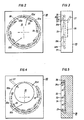
- the front view shown in FIG. 2 of a part of the slide plate 20 shows the region 22 which is delimited by an interrupted circular line 22b and which is in contact with the molten metal 1a when the slide plate 20 is in the closed position or from its corresponding part.
- the outflow openings of the nozzle 23 for the tangential supply of the gases are arranged in the edge zone 22a of this region 22.
- more tangential nozzles are arranged in the lower region 22c than in the upper region 22d. This results in a particularly good compensation for the differences in the ferrostatic pressure occurring over the cross section of the horizontal outflow channel 2 (FIG. 1) and thus a uniform flushing of the sensitive area of the slide.
- a porous stopper 25 (shown in dash-dot lines) seated in a recess of the slide plate 20 can be provided, from the center of the area 22 and surrounded by the nozzle openings 23, from which, also fed by Broken lines indicated supply line 27, the gases are introduced into the molten metal 1 over a large area and very finely distributed.
- the porous stopper 25 is also arranged in the upper partial region 22d of the slide 20, but there are no gas supply nozzles with an essentially tangential outflow direction arranged in this upper part; the porous stopper 25, for example made of zirconium oxide, takes on their task.
- the gas supply nozzles 23, which are essential to the invention and have a tangential outflow direction, are arranged in the lower region 22c, so that even with this embodiment variant, uniform flushing of the overall cross section is ensured despite the vertical arrangement of the slide plate.
- FIG 5 shows the section 22 of the slide plate 20 of another preferred embodiment of the device according to the invention, which is in contact with the melt 1 a in the closed position, in section.
- the gaseous medium is supplied via the ring channel 28 and the nozzles 23 penetrating tangentially through the cylindrical boundary wall 24a of the recess 24 in the slide plate 20.
- the boundary wall 24a of the recess 24 is located in the area of the edge zone 22a of the area 22 which is in contact with the molten metal 1 when the slide plate 20 is in the closed position, so that in this embodiment as well, the effect according to the invention of flushing the sensitive zones of the slide with gas is achieved.
- the slide plate 20 can be provided in a completely analogous manner.
Landscapes
- Engineering & Computer Science (AREA)
- Mechanical Engineering (AREA)
- Casting Support Devices, Ladles, And Melt Control Thereby (AREA)
- Continuous Casting (AREA)
- Furnace Charging Or Discharging (AREA)
Claims (10)
Applications Claiming Priority (2)
| Application Number | Priority Date | Filing Date | Title |
|---|---|---|---|
| AT5112/81 | 1981-11-27 | ||
| AT511281A ATA511281A (de) | 1981-11-27 | 1981-11-27 | Vorrichtung zum stranggiessen von metallen |
Publications (2)
| Publication Number | Publication Date |
|---|---|
| EP0080997A1 EP0080997A1 (fr) | 1983-06-08 |
| EP0080997B1 true EP0080997B1 (fr) | 1985-11-27 |
Family
ID=3572069
Family Applications (1)
| Application Number | Title | Priority Date | Filing Date |
|---|---|---|---|
| EP82890174A Expired EP0080997B1 (fr) | 1981-11-27 | 1982-11-23 | Dispositif pour la coulée continue de métaux |
Country Status (4)
| Country | Link |
|---|---|
| EP (1) | EP0080997B1 (fr) |
| JP (1) | JPS5893543A (fr) |
| AT (1) | ATA511281A (fr) |
| DE (1) | DE3267714D1 (fr) |
Families Citing this family (4)
| Publication number | Priority date | Publication date | Assignee | Title |
|---|---|---|---|---|
| AT383529B (de) * | 1985-10-24 | 1987-07-10 | Voest Alpine Ag | Einrichtung zum vergiessen von schmelzen |
| DE68927834T2 (de) * | 1989-06-01 | 1997-10-02 | Shinagawa Refractories Co | Plattenförmiger stein oder verteilerstein zum einblasen von gas für geschmolzenes metall |
| US5613545A (en) * | 1991-11-12 | 1997-03-25 | Shinagawa Refractories Co. Ltd. | Inert gas injecting plate brick or insert nozzle brick for use in a sliding gate valve apparatus of molten metal |
| CN118385557B (zh) * | 2024-06-05 | 2025-05-02 | 靖江市科尼机械配件有限公司 | 一种防漏型倾斜浇铸装置 |
Citations (3)
| Publication number | Priority date | Publication date | Assignee | Title |
|---|---|---|---|---|
| DE6918019U (de) | 1968-05-09 | 1970-05-06 | Asieries Reunies De Burbach Ei | Vorrichtung zum giessen von metallen, insbesondere von stahl, in kokillen |
| DE2462292A1 (de) | 1973-03-01 | 1977-02-17 | Uss Eng & Consult | Gasdurchlaessiger sperrschieber eines bodenauslassventils an einem giessgefaess |
| DE2811546A1 (de) | 1977-03-18 | 1978-09-21 | Sumitomo Metal Ind | Verfahren und vorrichtung zum kontinuierlichen giessen von stahl |
Family Cites Families (4)
| Publication number | Priority date | Publication date | Assignee | Title |
|---|---|---|---|---|
| GB801819A (en) * | 1956-03-22 | 1958-09-24 | Bram Joel Franklin | Improvements in the continuous forming of molten materials |
| CH478613A (de) * | 1968-07-12 | 1969-09-30 | Interstop Ag | Schiebeverschluss für mit einer Bodenausgussöffnung versehene Behälter zum Giessen von flüssigen Metallen, insbesondere Stahl |
| US3809146A (en) * | 1972-02-18 | 1974-05-07 | Steel Corp | Method of opening an intermediate vessel nozzle for continuous casting |
| DE2836409C2 (de) * | 1978-08-19 | 1982-07-22 | Stopinc AG, Zug | Vorrichtung zum Einführen von Behandlungsstoffen in die in einem metallurgischen Gefäß enthaltene Schmelze |
-
1981
- 1981-11-27 AT AT511281A patent/ATA511281A/de not_active Application Discontinuation
-
1982
- 1982-11-19 JP JP20218082A patent/JPS5893543A/ja active Pending
- 1982-11-23 DE DE8282890174T patent/DE3267714D1/de not_active Expired
- 1982-11-23 EP EP82890174A patent/EP0080997B1/fr not_active Expired
Patent Citations (3)
| Publication number | Priority date | Publication date | Assignee | Title |
|---|---|---|---|---|
| DE6918019U (de) | 1968-05-09 | 1970-05-06 | Asieries Reunies De Burbach Ei | Vorrichtung zum giessen von metallen, insbesondere von stahl, in kokillen |
| DE2462292A1 (de) | 1973-03-01 | 1977-02-17 | Uss Eng & Consult | Gasdurchlaessiger sperrschieber eines bodenauslassventils an einem giessgefaess |
| DE2811546A1 (de) | 1977-03-18 | 1978-09-21 | Sumitomo Metal Ind | Verfahren und vorrichtung zum kontinuierlichen giessen von stahl |
Also Published As
| Publication number | Publication date |
|---|---|
| JPS5893543A (ja) | 1983-06-03 |
| ATA511281A (de) | 1987-03-15 |
| DE3267714D1 (en) | 1986-01-09 |
| EP0080997A1 (fr) | 1983-06-08 |
Similar Documents
| Publication | Publication Date | Title |
|---|---|---|
| DE4023484C2 (fr) | ||
| DE2709727C3 (de) | Einrichtung zum Auswechseln von Gießrohren an Gießgefäßen beim Stranggießen | |
| DE2455181A1 (de) | Verfahren und vorrichtung zum vergiessen von metallen aus giessgefaessen, deren bodenauslassoeffnung durch einen gleitschieber einstellbar ist | |
| DE1951447C3 (de) | Ausflußschieberverschluß für Gefäße zum Vergießen von Metallen | |
| DE2557726A1 (de) | Vorrichtung zum auswechseln von giessrohren, insbesondere fuer einen mit einem schieberverschluss absperrbaren ausguss an einem zwischenbehaelter von stranggussanlagen | |
| DE3924001C2 (de) | Doppelrollen-Stranggießmaschine | |
| DE2355015A1 (de) | Giessvorrichtung mit horizontaler gleitkokille | |
| EP0080997B1 (fr) | Dispositif pour la coulée continue de métaux | |
| DE4138655C2 (de) | Ausflußregler für Zwischengefäß | |
| DE3331483C2 (de) | Einrichtung für feuerfeste Platten von Schieberverschlüssen | |
| DE2923493A1 (de) | Verfahren und vorrichtung zum entgasen von geschmolzenem metall | |
| DE1471914B2 (de) | Vorrichtung zur herstellung von tafelglas | |
| DE2738587C2 (de) | Verstellvorrichtung für eine Abschirmvorrichtung zum Gießstrahlschutz | |
| DE69612992T2 (de) | Verfahren und vorrichtung zum giessen eines metallbandes | |
| DE2261296C3 (de) | Gießbehalter fur Metall | |
| DE3342071C2 (de) | Vorrichtung zum Abschirmen eines metallischen Gießstrahls | |
| DE1213965B (de) | Vorrichtung zum kontinuierlichen Giessen von Baendern aus Metall oder anderen schmelzbaren Werkstoffen | |
| DE2607379B2 (de) | Vorrichtung zum spuelen von stahl | |
| DE4032787A1 (de) | Vorrichtung zum anschliessen eines giessrohres an den ausguss eines metallschmelze enthaltenden gefaesses | |
| DE2319004A1 (de) | Stopfenbetaetigungseinrichtung fuer giesspfanne | |
| DE2613363A1 (de) | Stranggussmaschine | |
| DE102008005727B3 (de) | Zuführeinrichtung für eine Metallschmelze und eine mit einer solchen Vorrichtung ausgestattete Bandgießeinrichtung | |
| DE2462292A1 (de) | Gasdurchlaessiger sperrschieber eines bodenauslassventils an einem giessgefaess | |
| DE1295757B (de) | Vorrichtung zur Entnahme von fluessigem Metall und Schlacke aus der axial angeordneten Entleerungsoeffnung eines Drehrohrofens | |
| WO2023174796A1 (fr) | Dispositif de distribution destiné à distribuer de façon intermittente un fluide de refroidissement sur une barre de coulée |
Legal Events
| Date | Code | Title | Description |
|---|---|---|---|
| PUAI | Public reference made under article 153(3) epc to a published international application that has entered the european phase |
Free format text: ORIGINAL CODE: 0009012 |
|
| AK | Designated contracting states |
Designated state(s): BE CH DE FR GB IT LI SE |
|
| 17P | Request for examination filed |
Effective date: 19830712 |
|
| RAP1 | Party data changed (applicant data changed or rights of an application transferred) |
Owner name: ZIMMERMANN & JANSEN GMBH Owner name: HAISSIG, MANFRED, DIPL.-ING. |
|
| ITF | It: translation for a ep patent filed | ||
| GRAA | (expected) grant |
Free format text: ORIGINAL CODE: 0009210 |
|
| AK | Designated contracting states |
Designated state(s): BE CH DE FR GB IT LI SE |
|
| REF | Corresponds to: |
Ref document number: 3267714 Country of ref document: DE Date of ref document: 19860109 |
|
| ET | Fr: translation filed | ||
| PLBI | Opposition filed |
Free format text: ORIGINAL CODE: 0009260 |
|
| 26 | Opposition filed |
Opponent name: DIDIER-WERKE AG Effective date: 19860825 |
|
| PG25 | Lapsed in a contracting state [announced via postgrant information from national office to epo] |
Ref country code: DE Effective date: 19871113 |
|
| PG25 | Lapsed in a contracting state [announced via postgrant information from national office to epo] |
Ref country code: SE Effective date: 19871124 |
|
| RDAG | Patent revoked |
Free format text: ORIGINAL CODE: 0009271 |
|
| STAA | Information on the status of an ep patent application or granted ep patent |
Free format text: STATUS: PATENT REVOKED |
|
| BERE | Be: lapsed |
Owner name: ZIMMERMANN & JANSEN G.M.B.H. Effective date: 19871130 Owner name: HAISSIG MANFRED Effective date: 19871130 |
|
| GBPR | Gb: patent revoked under art. 102 of the ep convention designating the uk as contracting state | ||
| 27W | Patent revoked |
Effective date: 19880124 |
|
| REG | Reference to a national code |
Ref country code: CH Ref legal event code: PL |
|
| EUG | Se: european patent has lapsed |
Ref document number: 82890174.4 Effective date: 19880913 |